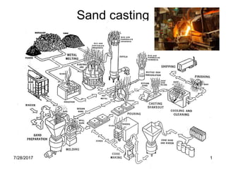
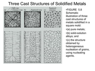
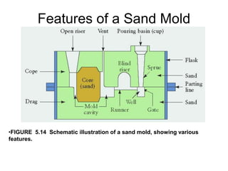
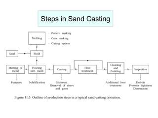
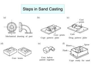
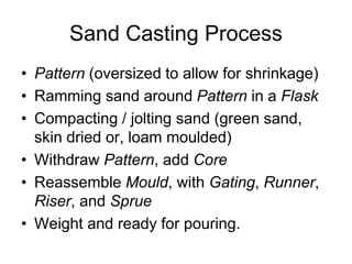
Sand casting
7/28/2017 1
Sand casting
7/28/2017 2
Sand casting
7/28/2017 3
Solidification of Pure Metals
Three Cast Structures of Solidified Metals
•FIGURE 5.8
Schematic
illustration of three
cast structures of
metals solidified in a
square mold:
•(a) pure metals;
•(b) solid-solution
alloys; and
•(c) the structure
obtained by
heterogeneous
nucleation of grains,
using nucleating
agents.
Features of a Sand Mold
•FIGURE 5.14 Schematic illustration of a sand mold, showing various
features.
Figure 11.5 Outline of production steps in a typical sand-casting operation.
Steps in Sand Casting
Sand Casting Process
• Pattern (oversized to allow for shrinkage)
• Ramming sand around Pattern in a Flask
• Compacting / jolting sand (green sand,
skin dried or, loam moulded)
• Withdraw Pattern, add Core
• Reassemble Mould, with Gating, Runner,
Riser, and Sprue
• Weight and ready for pouring.
Process Parameters
• Pouring Temperature
• Cooling rate
• Fluidity (viscosity)
Limit of flow before freezing
Spiral mould
Grain
Structure
Shrinkage
• Liquid
contraction
• Solidification
shrinkage
• Solid thermal
contraction
Shrinkage
Directional shrinkage
Parting Line
Figure 12.5 Redesign of a casting by making the parting line straight to avoid defects..
Patterns for Sand Casting
Figure 11.6 A typical metal
match-plate pattern used in
sand casting.
Figure 11.7 Taper on patterns for
ease of removal from the sand mold.
Pattern Material Characteristics
TABLE 11.3
Rating
a
Characteristic Wood Aluminum Steel Plastic Cast iron
Machinability E G F G G
Wear resistance P G E F E
Strength F G E G G
Weightb E G P G P
Repairability E P G F G
Resistance to:
Corrosionc E E P E P
Swellingc P E E E E
aE, Excellent; G, good; F, fair; P, poor.
bAs a factor in operator fatigue.
cBy water.
Source : D.C. Ekey and W.R. Winter, Introduction to Foundry Technology. New York.
McGraw-Hill, 1958.
Sand Casting - Pros
• Produce parts with complex geometries,
both internally and externally.
• Possible to net shape with no further
manufacturing required.
• Large parts can be produced.
• Wide choice of metals.
• Suitable for mass production.
Sand Casting - Cons
• Porosity
• Poor dimensional control for some
processes
• Poor surface finish for some processes
• Limitation on mechanical properties
• Safety hazard
• Environmental hazard
Product Design Considerations
• Geometric simplicity - Avoid unnecessary
complexity.
• Corners - Avoid sharp corners, generous fillet
radius.
• Section thickness - Uniform section thickness to
avoid shrinkage cavities and hot spots.
• Draft - Facilitate removal of parts from mold. (1 deg.
For sand and 2/3 deg. for permanent)
• Use of cores - minimize the use of core
• Dimensional tolerance and surface finish - proper
choice of casting method.
• Machining allowances - For assembly purposes,
typically 1.5 to 6 mm.
Product Design Considerations
Shrinkage, hot spot
Draft and core elimination
Product Design Considerations

3.sand casting

  • 1.
  • 2.
  • 3.
  • 4.
  • 5.
    Three Cast Structuresof Solidified Metals •FIGURE 5.8 Schematic illustration of three cast structures of metals solidified in a square mold: •(a) pure metals; •(b) solid-solution alloys; and •(c) the structure obtained by heterogeneous nucleation of grains, using nucleating agents.
  • 7.
    Features of aSand Mold •FIGURE 5.14 Schematic illustration of a sand mold, showing various features.
  • 8.
    Figure 11.5 Outlineof production steps in a typical sand-casting operation. Steps in Sand Casting
  • 9.
  • 10.
  • 11.
    Sand Casting Process •Pattern (oversized to allow for shrinkage) • Ramming sand around Pattern in a Flask • Compacting / jolting sand (green sand, skin dried or, loam moulded) • Withdraw Pattern, add Core • Reassemble Mould, with Gating, Runner, Riser, and Sprue • Weight and ready for pouring.
  • 12.
    Process Parameters • PouringTemperature • Cooling rate • Fluidity (viscosity) Limit of flow before freezing Spiral mould Grain Structure
  • 13.
  • 14.
  • 15.
    Parting Line Figure 12.5Redesign of a casting by making the parting line straight to avoid defects..
  • 16.
    Patterns for SandCasting Figure 11.6 A typical metal match-plate pattern used in sand casting. Figure 11.7 Taper on patterns for ease of removal from the sand mold.
  • 17.
    Pattern Material Characteristics TABLE11.3 Rating a Characteristic Wood Aluminum Steel Plastic Cast iron Machinability E G F G G Wear resistance P G E F E Strength F G E G G Weightb E G P G P Repairability E P G F G Resistance to: Corrosionc E E P E P Swellingc P E E E E aE, Excellent; G, good; F, fair; P, poor. bAs a factor in operator fatigue. cBy water. Source : D.C. Ekey and W.R. Winter, Introduction to Foundry Technology. New York. McGraw-Hill, 1958.
  • 18.
    Sand Casting -Pros • Produce parts with complex geometries, both internally and externally. • Possible to net shape with no further manufacturing required. • Large parts can be produced. • Wide choice of metals. • Suitable for mass production.
  • 19.
    Sand Casting -Cons • Porosity • Poor dimensional control for some processes • Poor surface finish for some processes • Limitation on mechanical properties • Safety hazard • Environmental hazard
  • 20.
    Product Design Considerations •Geometric simplicity - Avoid unnecessary complexity. • Corners - Avoid sharp corners, generous fillet radius. • Section thickness - Uniform section thickness to avoid shrinkage cavities and hot spots. • Draft - Facilitate removal of parts from mold. (1 deg. For sand and 2/3 deg. for permanent) • Use of cores - minimize the use of core • Dimensional tolerance and surface finish - proper choice of casting method. • Machining allowances - For assembly purposes, typically 1.5 to 6 mm.
  • 21.
    Product Design Considerations Shrinkage,hot spot Draft and core elimination
  • 22.