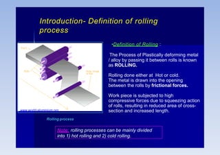
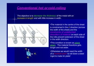
Rolling is a metal forming process where metal stock is passed through one or more pairs of rolls to reduce the thickness and increase the length. There are two main types:
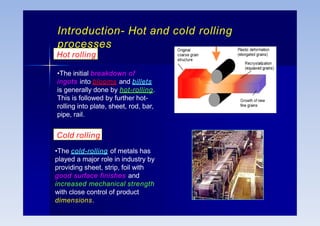
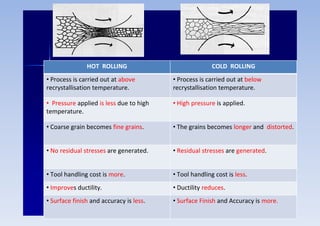
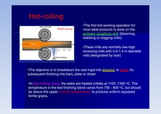
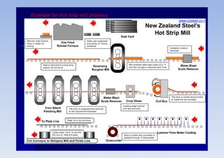
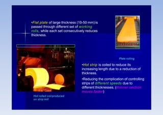
1) Hot rolling is performed above the metal's recrystallization temperature for lower pressure and improved ductility. It produces coarse grains and no residual stresses.
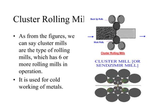
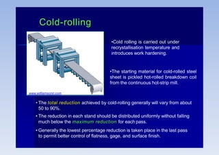
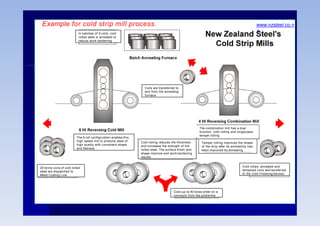
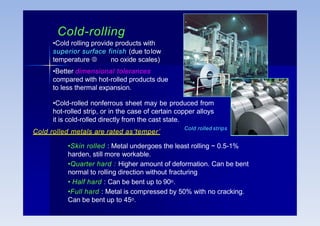
2) Cold rolling is performed below the recrystallization temperature, requiring higher pressures but improving dimensions, finish and strength through residual stresses and elongated grains.
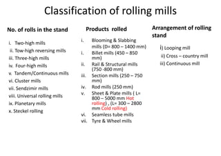
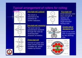
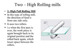
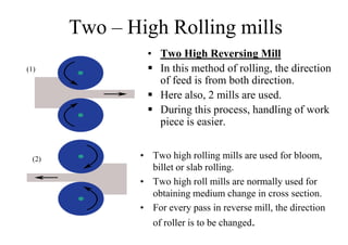
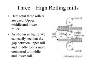
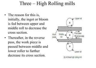
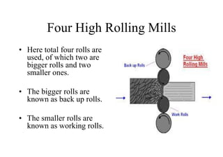
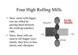
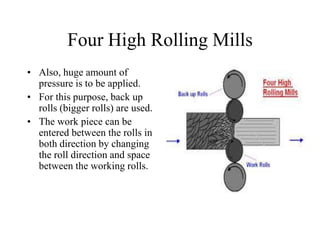
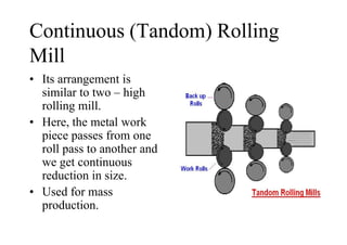
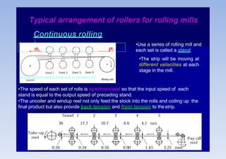
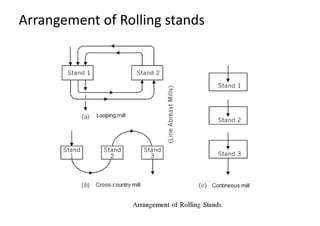
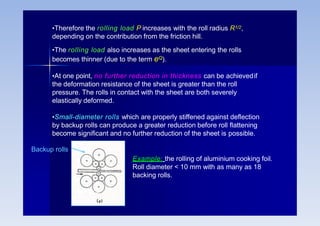
Rolling mills are classified by the number of rolls used, including two-high, three-high, four-high and cluster/sendzimir mills. Continuous mills use multiple stands to continuously roll sheet metal.