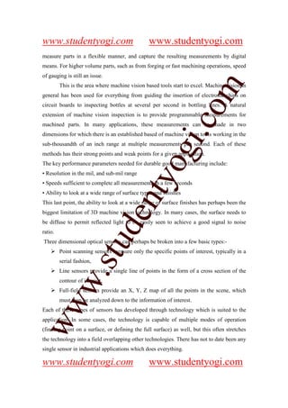
ww
1) 3D machine vision systems have advanced to enable quantitative metrology applications on the shop floor. Technologies like laser scanning, structured light, and stereo viewing can provide measurements at sub-mil resolution and speeds sufficient for inspection.
2) Key challenges for 3D optical systems include varying surface finishes and textures that can scatter or diffuse light signals. Thorough testing on representative surfaces and features is important to validate measurement capabilities.
3) Comparisons to independent measurement methods help qualify new 3D vision systems, as traditional gauges may not provide the same level of capability or repeatability. Standard artifacts can verify optical measurements.
3d Machine Vision Systems Paper Presentationguestac67362
ww
1) 3D machine vision systems have advanced to enable quantitative metrology applications on the shop floor. Technologies like laser scanning, structured light, and stereo vision can provide measurements in the sub-mil range at speeds of a few seconds.
2) Key factors for production use are measurement resolution in mils/sub-mils, speeds under a few seconds, and robustness to varying surface finishes and conditions. Technologies were tested on features like edges, textures, and spheres to evaluate performance.
3) Applications include industrial inspection, autonomous vehicles, transport safety, surveillance, remote sensing, and medical imaging. Continued improvements in computing, cameras, and light sources will further expand use of 3D machine
Provides high accuracy for component inspection and significantly reduces cycle time. There are three variants of the high-performance vision measuring instrument.
Machine vision uses computer vision techniques to automate inspection and measurement tasks in manufacturing processes. It incorporates computer science, optics, and mechanical engineering. Machine vision systems typically use digital cameras and specialized lenses to capture images that are then processed to check for attributes like dimensions, serial numbers, and defects. Common applications include inspecting semiconductor chips, automobiles, food, and pharmaceuticals. Key components of machine vision systems include cameras, lighting, lenses, and image processing software to analyze the captured images.
A machine vision system uses cameras and computer processing to simulate the human ability to recognize images. It performs image sensing, analysis, and interpretation to automatically acquire data about objects, measure image features, recognize objects, and make decisions. The process involves a camera capturing an image of an object under light, the computer analyzing the image characteristics, and either communicating defects to a rejection unit or sending defect-free parts for further processing. Key steps are image formation, processing the image for computer analysis, defining and analyzing image characteristics, and interpreting the image and making decisions. Machine vision is used for inspection, identification, guidance and control in various applications like quality assurance, defect detection, testing and calibration.
This document discusses machine vision systems and their applications in semiconductor manufacturing. It begins with definitions of machine vision systems and an overview of their components and functions. It then discusses various applications of machine vision in semiconductor front-end and back-end processes like inspection, metrology, and assembly. Specific applications mentioned include inspection of wafers, dies, packages, leads, and printed circuit boards. The document provides examples of machine vision aiding processes like die bonding, wire bonding, laser marking, and automated assembly.
INDUSTRIAL APPLICATION OF MACHINE VISION ppt mrng finlanil badiger
This document discusses the industrial application of machine vision. It begins with definitions of machine vision and descriptions of its key components like light sources, lenses, sensors, and processing units. It then explains the basic working principle of how a camera captures an image of an object, the computer analyzes the image characteristics, and communicates acceptance or rejection. Some common application fields are listed as automotive, electronics, food, and manufacturing. Specific applications like measurement, counting, location, and decoding are then described in more detail with examples. The document concludes that machine vision provides benefits like speed, consistency, reliability, and ability to operate in hazardous environments.
What is Machine Vision?
History of Machine Vision
Introduction of Machine Vision
What are its advantages and disadvantages?
What are its applications?
What are the com[onents of Machine Vision?
Machine vision v/s Human inspectors
The document discusses a vision system for robotics and servo motors. It begins by covering basic camera concepts like lenses, focal length, pixels and resolution. It then discusses image processing techniques like histograms, thresholds, and blob analysis. It concludes by describing servo motors, how they use closed-loop control systems to provide feedback-controlled motion, and some of their applications.
Machine vision is a technology that uses imaging and cameras to provide automatic inspection and analysis for applications like quality control, process monitoring, and robot guidance. It can check for attributes like dimensions, patterns, and defects. A typical machine vision system consists of cameras, lighting, image processing software, and actuators. The general process involves image capture, preprocessing, analysis of regions of interest, feature extraction, and decision making.
Machine Vision In Electronic & Semiconductor IndustryFrancy Abraham
What is machine vision system (vision system)
Definition
Operation scope
Engineering domain
Applications in general
Industries that use vision systems
Vision system components - Introduction
Image processing - Introduction
Vision system functions - Introduction
Vision system performance
Introduction to applications in electronic & semiconductor manufacturing
Semiconductor front-end inspection & metrology
Semiconductor back-end inspection & metrology
IC assembly applications
IC handling, inspection & metrology
Leadframe inspection & metrology
PCBA/Substrate assembly inspection
This document discusses machine vision systems and their components. A basic machine vision system includes a camera, light source, frame grabber, circuitry and programming, and a computer. Key components of machine vision systems are the image, camera, framegrabber, preprocessor, memory, processor, and output interface. The document also describes CCD and vidicon cameras, their advantages and disadvantages, and the functions of framegrabbers in sampling and quantizing images. Object properties that can be analyzed from pixel grey values include color, specular properties, non-uniformities, lighting. Applications of machine vision systems are also mentioned.
Aiar. unit v. machine vision 1462642546237Kunal mane
Machine vision systems are used to perform tasks such as part selection, identification, and inspection. A typical machine vision system consists of a camera, digitizing hardware, and a computer for image processing and analysis. The key functions of a vision system are sensing and digitizing image data, image processing and analysis, and application of the results. Image processing techniques used include data reduction methods like digital conversion and windowing, segmentation methods like thresholding, region growing and edge detection, and feature extraction to analyze objects and enable recognition. Machine vision has applications in industrial inspection, identification, and visual servoing and navigation in robotics.
3D scanning technology allows capturing the shape of physical objects and environments digitally. It works by using techniques like laser triangulation, structured light, photogrammetry, or contact-based scanning to obtain high-density 3D measurements. The results can be used for reverse engineering, rapid prototyping, inspection, and analysis. Different scanning methods have advantages and limitations depending on factors like speed, resolution, ability to scan people or outdoor environments, and sensitivity to lighting or surface properties. The document discusses several 3D scanning technologies and their applications in industries like automotive, aeronautics, and entertainment.
This document describes an inspection system that uses machine vision to inspect bottles of liquid medicine on a production line. The system uses a camera and MATLAB software to analyze images of bottles and check that the liquid level and bottle cap meet specifications. It summarizes the experimental setup, image processing and analysis methods, and results of testing the system on 4 sample bottles. The system was able to accurately inspect the bottles and determine if they passed or failed inspection of the liquid level and bottle cap.
The document provides an overview of machine vision and its components. It discusses the top five industrial users of machine vision, common machine vision applications, and key components like lenses, cameras, lighting, and software tools. It also outlines steps for selecting a machine vision vendor, including defining requirements, researching technology options, evaluating solutions, and performing a risk assessment.
An Accurate Scheme for Distance Measurement using an Ordinary Webcam Yayah Zakaria
Nowadays, image processing has become one of the widely used computer aided science. Two major branches of this scientific field are image enhancement and machine vision. Machine vision has many applications and demands in robotic and defense industries. Detecting distance of objects is
one of the extensive research in the defense industry and robotic industries that a lot of annual projects have been involved in this issue both inside and outside the country. So, in this paper, an accurate algorithm is presented for measuring the distance of the objects from a camera. In this method, a laser
transmitter is used alongside a regular webcam. The laser light is transmitted to the desired object and then the distance of the object is calculated using image processing methods and mathematical and geometric relations. The performance of the proposed algorithm was evaluated using MATLAB software. The accuracy rate of distance detection is up to 99.62%. The results
also has shown that the presented algorithms make the obstacle distance measurement more reliable. Finally, the performance of the proposed algorithm was compared with other methods from different literatures.
The document discusses digital image correlation (DIC), a non-contact optical technique for measuring surface deformation. DIC uses high-resolution cameras and digital image processing to track features on a material's surface as it deforms. This allows DIC to measure displacements, strains, and other values over thousands of points. DIC provides a rich data set for analyzing how materials respond to forces in both static and dynamic testing.
This document provides an introduction to computer vision. It defines computer vision as using image processing and computer algorithms to interpret images and videos. The goal of computer vision is to bridge the gap between pixels in an image and the meaningful objects and scenes that humans perceive. Computer vision systems aim to interpret images at low, mid, and high semantic levels, from basic measurements and features to activities and deep understandings. The document outlines challenges in computer vision like viewpoint and illumination variations, occlusions, scales, deformations, and clutter. It also discusses how human vision differs from computer interpretations.
Image processing involves the alteration and analysis of pictorial information. There are two main methods: optical processing using lenses and electronic processing. Electronic processing can be analog, controlling brightness and contrast, or digital, where images are composed of pixels that can be processed by a computer. Image processing has applications in fields like robotics, medicine, graphics, and satellite imaging. It allows for tasks like image restoration, compression, and segmentation.
Mechanical Engineering Technical Interview Q & A Metrology and precision inst...Er. Bade Bhausaheb
This document discusses various metrology and precision instruments used for measurement and inspection. It provides definitions and explanations of nominal size, actual size, basic size, fits, limits, tolerance, allowance and describes instruments like vernier calipers, micrometers, gauges, sine bars and templates. Key points covered are the working principles and uses of these instruments as well as concepts like interchangeability, selective and non-selective assembly, lapping and honing processes.
The document discusses human vision versus machine vision systems (MVS). It outlines the components and working principles of MVS, including imaging fundamentals, design requirements, and integration of various engineering disciplines. Tables compare key capabilities and performance criteria of human versus machine vision, such as distance, motion detection, recollection, distinguishing colors/details, time delay, intelligence level, and operating environment. The document notes disadvantages of human vision and advantages of MVS, and lists some applications of MVS.
This document discusses optical measurement techniques. It describes how optical measurement systems work by using lighting, optics, and cameras to capture images and measure objects non-invasively. It notes both advantages, such as being non-invasive, and disadvantages, such as not being able to compensate for errors like a human could. Finally, it provides examples of applications that are well-suited for optical measurement like flat parts, profiles, and 3D parts with small features.
Profilograph-profilometr is capable to provide measurement of parameters of surfaces in three-dimensional (3D) the image of their condition to within 1нм on height of a relief. This device allows to receive qualitatively new information which, in turn, will lead to development and creation of the newest technologies in mechanical engineering
Design Description of a Tentacle Based Scanning SystemOyeniyi Samuel
This document describes the design of a tentacle-based 3D scanning device. The scanner uses a camera and two lasers for distance measurement via triangulation. As an object on a turntable rotates, the camera and lasers move up and down via a lead screw to scan the entire object. The scanner is intended to be low-cost and portable for use in scanning small objects up to 15x15x20 cm in size and 500g in weight. It is designed using inexpensive and readily available materials like a polymer composite for rigidity. The main mechanisms are NEMA stepper motors to control the turntable and lead screw for camera/laser movement.
Introduction to Digital Image Correlation (DIC)Instron
This presentation introduces Digital Image Correlation, the optical technique that compares images of a tested specimen’s surface to generate full-field strain and displacement maps.
This document discusses key considerations for machine vision systems. It explains that vision systems are unique to each application and require custom engineering. It then discusses important elements like lighting, lenses, camera sensors, and integration with control systems. Proper lighting and component selection are essential for system success. The document also outlines common vision system types and imaging options like 2D and 3D.
This document provides an introduction and syllabus for a machine vision course. The 2-day course covers MATLAB basics, image processing fundamentals, and 4 projects involving content-based image retrieval, depth from stereo images, image segmentation, and object recognition. The instructor provides several demonstrations of computer vision applications and encourages students to directly start working on projects.
This document provides information about robotics and machine vision systems courses. The objectives are to study robot components, derive kinematics and dynamics equations, manipulate trajectories, and learn machine vision. Key topics covered include robot history, components, configurations like Cartesian and cylindrical, applications in material handling, processing, assembly, and inspection. Benefits of robots are also discussed.
1) Machine vision uses digital cameras and image processing to automate production processes and quality inspections by replacing manual methods.
2) A machine vision system involves four steps: imaging, image processing/analysis, communicating results to the control system, and taking appropriate action.
3) The main components of a machine vision system are cameras, lighting systems, frame grabbers, and computer/software to process images and analyze results.
Multi link structure for rear independent suspension of heavy vehicleIAEME Publication
Automobile systems today is going through major changes and as concert to comfort the suspension system and it’s working is very important. The study of four link suspension system and dynamic analysis are discussed in this paper. This paper discusses the design problem of vehicles using four-link suspension systems with the aim of totally optimizing vehicle handling and stability.
This document discusses robot vision systems. It covers topics like industrial robotics, medical robotics, computer vision capabilities for robotics like object recognition and registration, vision sensors, issues with vision systems, and visual servoing techniques. Application examples discussed include using vision for accurate robot positioning, laparoscopic surgery, and tracking instruments.
PPT on Suspension system in automobiles By Pukhraj palariyapukhraj palariya
The document discusses different types of suspension systems used in automobiles. It describes conventional suspension systems which use rigid axles connected to leaf springs. Independent suspension systems are also covered, including MacPherson strut, double wishbone, and multi-link designs which allow individual wheel movement. Air suspension uses air bags and compressors to maintain vehicle height. Hydroelastic and hydragas suspensions connect front and rear systems using fluid to better level the vehicle.
The document outlines topics to discuss regarding 3D vision technology, including a brief history. It covers early patents from 1880 and the first 3D movie from 1922. Methods of capturing 3D images are discussed as well as techniques for projection, such as anaglyph, polarization, interference filters, and Dolby 3D. The document also touches on classifying 3D formats and modern technologies that enable 3D without glasses, like autostereoscopic screens and holograms. References are provided at the end.
The document describes an experimental study on improving the productivity of gas metal arc welding (GMAW). It investigates the effect of varying three input parameters - welding current, voltage, and gas flow rate - on the amount of filler metal deposited and welding time. Samples of mild steel were welded using different combinations of the parameters and the weight of deposited metal and welding time were measured. The results showed that higher current leads to higher heat generation and metal deposition rate. Maximizing deposition rate while minimizing welding time can improve the productivity of GMAW.
EFFECT OF THE PROCESS PARAMETERS ON GEOMETRICAL CHARACTERISTICS OF THE PARTS ...IAEME Publication
This document reviews the direct metal deposition (DMD) process and the effects of various process parameters on the geometrical characteristics of parts produced. It discusses how the laser power, beam diameter, scanning speed, powder flow rate, and other parameters influence characteristics like clad height, width, roughness, and dilution. Several studies that developed models and conducted experiments relating parameters to outcomes are summarized. In general, increasing laser power or powder flow rate tends to increase clad height and deposition rate while increasing scanning speed decreases these. Optimal surface roughness requires intermediate parameter values.
The document discusses improving the performance of photopolymer resins used in 3D printing through oxygen desensitization. It examines adding visco enhancers and antioxidants to photopolymer resins to protect the ruthenium catalyst from deactivating in the presence of oxygen. Testing found that increasing the resin viscosity by 30x improved its ambient lifespan by over 100x. Adding the antioxidant 4-methoxyphenol (MEHQ) at 0.1-0.2 wt.% also improved performance by 9x. Raman spectroscopy confirmed MEHQ was the most effective antioxidant at protecting the catalyst compared to others tested. The modifications aim to allow photopolymer resins to polymerize after longer exposures to ambient oxygen levels.
The Technology Research of Camera Calibration Based On LabVIEWIJRES Journal
The technology of camera calibration is most important part for machine vision detection and
location, the accuracy of calibration directly determines the processing accuracy of machine vision systems. In
this paper, we use LabVIEW and MATLAB to calibrate the internal and external parameters of the camera, at
the same time, we use dot calibration board, the circle edge is detected by Canny operator, then with the method
of circle fitting based on subpixel edge extraction, the information of dots image coordinate is extracted. The
present method reduces the difficulty of camera calibration and shortens the software development cycle, the
most important is that it has a high calibration accuracy, which can meet the actual industrial detection accuracy,
the results of experimental show that the method is feasible.
A study on improvement activities for indian manufacturing industrieseSAT Journals
Abstract This paper presents findings of an extensive survey of Indian manufacturing industries. The survey encompassed three sectors: Four Wheeler Automobile Industries, Two Wheeler Automobile Industries and General Manufacturing Industries. Various Improvement Activities such as Advance Manufacturing Technology, Integrated Information System and Advance Management System have been identified and assessed the degree of investment in Improvement Activities in Indian manufacturing environment. Their sub classifications are also made. Sector wise comparisons of these Improvement Activities are provided. Correlation is also made between the various Improvement Activities. Our results showed that most of the Indian industries are still emphasizing Advanced Management Systems. Four Wheeler Automobile Industries and General Manufacturing Industries are emphasizing on Total Quality Management. However Two Wheeler Automobile Industries are investing more on Activity Based Costing. But, in overall sector it is observed from data analysis that all sectors are emphasizing on Total Quality Management. Key words: Improvement activities, Advance Manufacturing Technology, Integrated Information System, Advance Management System.
Advanced Materials and Processes Magazine - January 2015 - Additive Manufactu...Machine Tool Systems Inc.
Attached is a research paper about DMLS™ and steels that appeared in the January edition of Advanced Materials and Processes magazine. The paper is authored by engineers at EWI, an EOS partner.
IBC Group provides advanced surface treatment and coating solutions using techniques like laser cladding, thin film coating, nitriding, and heat treating. The company has facilities in Indiana and Canada with about 85 employees. Laser cladding is used to rebuild worn components and increase hardness and wear resistance through applying cladding layers and subsequent treatments. Examples showed laser cladding repaired turbo shafts and agricultural parts with no wear after testing.
Effect of chromium powder mixed dielectric on performance characteristic of a...eSAT Journals
Abstract
In this paper, the effect of chromium powder mixed dielectric fluid on machining characteristics of AISI D2 die steel has been studied. Peak current, pulse on time, pulse off time, concentration of powder are the process parameters. The process performance is measured in terms of material removal rate (MRR), tool wear rate (TWR) and surface roughness (SR). The research outcome will identify the important process parameters that maximize MRR, minimize TWR and SR. The design of experiment has been undertaken using Taguchi method. ANOVA analysis has been used to investigate the percentage contribution of each process parameter for optimizing the performance. The study indicates that all the selected parameters except pulse off time have a significant effect on MRR. Current is found to be the most significant factor for MRR and TWR. With increase in current, TWR increases. Also, surface roughness increases with increase in pulse off time.
Keywords: PMEDM, Material removal rate, Tool wear rate, Surface roughness, Taguchi method
LaserBond™ achieves a welded or metallurgical bond with minimal, precisely controlled heat input provided by an optimized laser beam. Temperature sensitive components and materials, such as hardened shafts, gears etc, can be repaired with minimal risk of distortion or other undesirable heat effects. The metallurgical bond allows LaserBond™ applied layers to be used in high impact, heavily loaded/stressed situations with no risk of spalling or separation of the overlay. The controlled energy minimizes the undesirable thermal decomposition of hard phases such as carbides, resulting in optimum wear resistance. Due to the extremely low dilution with the substrate, high specification materials can be applied in a thin layer with corrosion and wear resistant surfaces as thin as 0.3mm possible. Thick overlays for significant repairs of up to 20mm can also be applied in multiple passes. Heat affected zones are minimized and the stress related cracking inherent in welded or PTA applied hard facing is generally eliminated. Standard LaserBond™ overlay options include Tungsten Carbide, Stainless Steels, Nickel alloys such as Inconel, and Cobalt alloys such as Stellite1. Other materials can be applied on request.
The High Pressure High Velocity Oxy-Fuel process applies coating material at supersonic velocities, resulting in surfaces of the highest possible quality and performance.
HP HVOF coatings are very dense, very well bonded, and free of the oxides and tensile stresses typically found in coatings produced with other thermal spray processes. Consequently, they perform better in most service environments. HP HVOF wear resistant coatings are being adopted globally as an environmentally friendly, and technically superior, alternative to Chrome plating on components such as aircraft landing gear. Surfaces combining resistance to corrosion and wear are also routinely applied by HP HVOF. LaserBond™ approved HP HVOF coatings include Tungsten Carbide, Chrome Carbide, Nickel based alloys (e.g. Inconel 625 and 718), Cobalt alloys such as Stellite1, stainless steels and copper based alloys.
Ajith Ranasinghe | Sales Engineer
LaserBond Ltd
2/57 Anderson Road, Smeaton Grange NSW 2567
| m:+61417618512 | t: +612 4631 4500 | f: +612 4631 4555
ajithr@laserbond.com.au
This document discusses 3D machine vision systems and their use as metrology tools on the shop floor. It provides an overview of different 3D machine vision technologies like laser scanning, structured light, and stereo viewing. It discusses their capabilities and limitations, as well as advances that have enabled more quantitative shop floor metrology applications. Key performance parameters for these systems include sub-mil resolution, measurement speeds of a few seconds, and ability to measure a wide range of surface finishes. The document also evaluates these systems through application testing and comparison to other measurement tools.
This document discusses rendering algorithms and techniques. It begins by defining rendering as the process of generating 2D or 3D images from 3D models. There are two main categories of rendering: real-time rendering used for interactive graphics, and pre-rendering used where image quality is prioritized over speed. The three main computational techniques are ray casting, ray tracing, and shading. Ray tracing simulates physically accurate lighting by tracing the path of light rays. Shading determines an object's shade based on attributes like diffuse illumination and light source contributions.
Measurement techniques in micro machining PDF by badebhau4@gmail.comEr. Bade Bhausaheb
This document discusses various measurement techniques used in micro machining. It begins by explaining the need for developing new measurement techniques capable of accurately measuring micro-scale features between 0.1 to 100 μm. It then categorizes measuring systems as either dimensional or topographic and describes examples in each category. Key techniques discussed include optical microscopes, electron microscopes like SEM, interferometers, profilometers, scanning probe microscopes and laser-based systems. The document provides details on operating principles, applications, accuracy and resolution limits of these micro-measurement techniques.
This document discusses a method called cone tracing, which is a variant of ray tracing that can be used to render realistic soft shadows and glossy reflections more efficiently than traditional ray tracing. The key aspects are:
- Cone tracing models light as conical volumes rather than individual rays, reducing the number of intersections needed while avoiding noise.
- The paper presents a rendering engine that uses both cone tracing and ray tracing modules to produce shadows and reflections. Cone tracing is used to determine occlusion and reflection colors at ray intersection points.
- Intersection algorithms are approximated for cones, which have linear widening, rather than solved directly through systems of equations like with rays. This achieves accurate results more efficiently
A Review on Deformation Measurement from Speckle Patterns using Digital Image...IRJET Journal
This document reviews digital image correlation (DIC) for deformation measurement using speckle patterns. DIC is a non-contact optical method that uses digital images of a speckle pattern on a surface before and after deformation. By comparing the speckle patterns in the images, DIC can determine displacement and strain fields with high accuracy. The document discusses speckle pattern types, the DIC process, related works that have improved DIC methods, and applications of DIC such as for high-temperature testing. DIC provides full-field measurements and greater accuracy compared to conventional contact methods.
An algorithm to quantify the swelling by reconstructing 3D model of the face with stereo images is presented. We
analyzed the primary problems in computational stereo, which include correspondence and depth calculation. Work has been carried out to determine suitable methods for depth estimation and standardizing volume estimations. Finally we designed software for reconstructing 3D images from 2D stereo images, which was built on Matlab and Visual C++. Utilizing
techniques from multi-view geometry, a 3D model of the face was constructed and refined. An explicit analysis of the stereo
disparity calculation methods and filter elimination disparity estimation for increasing reliability of the disparity map was
used. Minimizing variability in position by using more precise positioning techniques and resources will increase the accuracy of this technique and is a focus for future work
This document summarizes an analysis of iris recognition based on false acceptance rate (FAR) and false rejection rate (FRR) using the Hough transform. It first provides an overview of iris recognition and its typical stages: image acquisition, localization/segmentation, normalization, feature extraction, and pattern matching. It then describes existing methods used in each stage, including the Hough transform and rubber sheet model for localization and normalization. The proposed methodology applies Canny edge detection, Hough transform for boundary detection, normalization with the rubber sheet model, and calculates metrics like mean squared error, root mean squared error, signal-to-noise ratio, and root signal-to-noise ratio to evaluate the accuracy of iris recognition using FAR
Reverse engineering is the process of analyzing an existing system or product to identify its components and design in order to extract design details without prior documentation. It involves digitizing a physical object using 3D scanning techniques like contact methods, non-contact active methods, and non-contact passive methods to obtain point cloud data. This point cloud data is then processed to generate CAD models through techniques like polygonization and refinement. The final CAD models can then be used for applications like redesign, quality control, and rapid prototyping.
Lets Understand the overall working of photogrammetry. Get ideas about photogrammetry branches. Also, check the difference between photogrammetry and remote sensing.
An Efficient Algorithm for Edge Detection of Corroded SurfaceIJERA Editor
Inspection process in industrial applications plays a vital role as it directly hinders the outages of industry. Thereby the inspection especially in case of corroded surfaces is to be fast, precised and accurate. Visual inspection has been very liable to mistakes because of numerous facts. The automatic inspection systems remove subjective aspects and can provide fast and accurate inspection. Inspection of corroded surfaces is very important concern, thus it is required to detect corroded surfaces. A new algorithm is developed by certain changes in mask and thresholding selection to detect corroded surfaces. The paper is about how we can amend the weak edges of input images and discarding false edges to overcome the problem of traditional techniques in this field. Proposed operator also compared with two commonly used edge detection algorithms which are Canny and Sobel.
The document presents a 3-D environment modeling and adaptive foreground detection system for multi-camera surveillance. The system constructs a 3-D model of the environment using planar patches approximated from camera views. Videos are integrated and displayed on the 3-D model using texture mapping. A novel method is proposed to detect moving shadows in two phases: an offline training phase determines pixel-wise thresholds, and an online phase updates the thresholds over time to adapt to different scenes. Foreground objects are extracted accurately after removing shadows and displayed using axis-aligned billboarding for 3-D visualization.
This document discusses techniques for achieving visual realism in geometric modeling. It covers topics like hidden line removal, hidden surface determination, shading models, transparency, reflection, and camera models. The goal of visual realism is to generate images that capture effects of light interacting with physical objects similarly to how we see the real world. This involves modeling objects and lighting conditions, determining visible surfaces, assigning color to pixels, and creating animated sequences. Realistic images find applications in simulation, design, entertainment, research, and control.
The document discusses different types of sensors used for 3D digitization, including passive and active vision techniques. It describes synchronization circuit-based dual photocells that improve measurement stability and repeatability. Position sensitive detectors are discussed that can measure the position of a light spot in one or two dimensions on a sensor surface to acquire high-resolution 3D images. A proposed sensor architecture combines color and range sensing for applications like hand-held 3D cameras.
Automated Laser Scanning System For Reverse Engineering And InspectionJennifer Daniel
This document summarizes an automated laser scanning system developed for reverse engineering and inspection of parts with freeform surfaces. The system generates optimal scan plans considering parameters like view angle, depth of field, and occlusion. It uses a laser scanner mounted on a motorized rotary table to automatically scan parts according to the generated scan plans. The point data is then automatically registered and evaluated by comparing to CAD models. The system aims to automate the scanning process for more efficient inspection and reverse engineering of complex parts.
3D Scanners and their Economic FeasibilityJeffrey Funk
These slides use concepts from my (Jeff Funk) course entitled analyzing hi-tech opportunities to analyze how the economic feasibility of 3D scanners is becoming better through improvements in lasers, camera ICs, and processor ICs. 3D scanning is both a complement to 3D printing and a technology with its own unique applications. 3D printing of complex objects can be done from a CAD database or from a 3D scan where a 3D scan can be done with laser or other sources of white light such as LEDs.
3D scanning can also be done for other purposes. For example, scientists and engineers are using 3D scanners to survey archeological, construction, crime scene, and engineering sites, to document maintenance and repair of engineered systems, and to customize medical and dental products for humans. Improvements in lasers, LEDs, camera chips, ICs, and other components continue to improve the economic feasibility of 3D scanning. Longer wavelength lasers increase the scanning range, better camera chips improve the scanning resolution, and better lasers, camera chips, and processor ICs reduce the scanning time. For example, third generation scanners from Argon, one leading supplier, have 100 times higher resolution and one tenth the scan times of Argon’s first generation system.
For costs, lasers make up the largest percentage followed by camera and processor ICs. For example, lasers make up 80% of the hardware cost for one high-end system with a current cost of $1346 and a price of about $3000. As laser costs fall and as volumes enable smaller margins, the price of such systems will fall.
For the same reasons, low-end systems continue to emerge. These include Microsoft’s Kinect and an app for the iPhone. Microsoft’s Kinect was $150 while the app was only $4.99, both in early 2013. As such low-end systems proliferate, and high-end systems continue to get cheaper, 3D scanning will find new applications.
The document discusses advances in metrology, including laser interferometry and coordinate measuring machines (CMMs). It describes the principles and components of laser interferometry, including laser sources, optical elements, and measurement receivers. Coordinate measuring machines are discussed, including their construction, types of probes, accuracy considerations, and applications for precision inspection. Computer-aided inspection using machine vision systems is also summarized, outlining the key stages of image generation, processing, and analysis.
This document discusses advances in metrology, specifically laser metrology and interferometry. It begins by explaining the principles and components of lasers and how they are used for precision measurement. Examples of laser measuring machines described include laser telemetric systems, laser and LED distance measuring instruments, scanning laser gauges, and laser interferometers. Interferometry uses laser beams to perform highly accurate linear and angular measurements. Coordinate measuring machines and digital devices for computer-aided inspection are also summarized.
IRJET- Real Time Implementation of Air WritingIRJET Journal
This document presents a system for real-time control of industrial devices through hand gestures from a remote location using a wireless system. The system uses a camera and microcontroller to detect when a red pointer is brought near different quadrants, representing different devices, and switches the corresponding device on or off. It was implemented using MATLAB and allows controlling systems wirelessly with accuracy while saving power through a simple circuit. The system provides remote management of devices without physical operation and could potentially be expanded to control additional parameters like speed or duration of operation.
These slides use concepts from my (Jeff Funk) course entitled analyzing hi-tech opportunities to analyze how Light Field Technology is becoming economic feasible for an increasing number of applications. Light Field Cameras record all of the light fields in a picture instead of just one light field. This capability enables users to change the focus of pictures after they have been taken and to more easily record 3D data. These features are becoming economically feasible improvements because of rapid improvements in camera chips and micro-lens arrays (an example of micro-electronic mechanical systems, MEMS). These features offer alternative ways to do 3D sensing for automated vehicles and augmented reality and can enable faster data collection with telescopes.
Similar to 3d machine-vision-systems-paper-presentation (20)
Top mailing list providers in the USA.pptxJeremyPeirce1
Discover the top mailing list providers in the USA, offering targeted lists, segmentation, and analytics to optimize your marketing campaigns and drive engagement.
Tata Group Dials Taiwan for Its Chipmaking Ambition in Gujarat’s DholeraAvirahi City Dholera
The Tata Group, a titan of Indian industry, is making waves with its advanced talks with Taiwanese chipmakers Powerchip Semiconductor Manufacturing Corporation (PSMC) and UMC Group. The goal? Establishing a cutting-edge semiconductor fabrication unit (fab) in Dholera, Gujarat. This isn’t just any project; it’s a potential game changer for India’s chipmaking aspirations and a boon for investors seeking promising residential projects in dholera sir.
Visit : https://www.avirahi.com/blog/tata-group-dials-taiwan-for-its-chipmaking-ambition-in-gujarats-dholera/
At Techbox Square, in Singapore, we're not just creative web designers and developers, we're the driving force behind your brand identity. Contact us today.
Structural Design Process: Step-by-Step Guide for BuildingsChandresh Chudasama
The structural design process is explained: Follow our step-by-step guide to understand building design intricacies and ensure structural integrity. Learn how to build wonderful buildings with the help of our detailed information. Learn how to create structures with durability and reliability and also gain insights on ways of managing structures.
Anny Serafina Love - Letter of Recommendation by Kellen Harkins, MS.AnnySerafinaLove
This letter, written by Kellen Harkins, Course Director at Full Sail University, commends Anny Love's exemplary performance in the Video Sharing Platforms class. It highlights her dedication, willingness to challenge herself, and exceptional skills in production, editing, and marketing across various video platforms like YouTube, TikTok, and Instagram.
Best practices for project execution and deliveryCLIVE MINCHIN
A select set of project management best practices to keep your project on-track, on-cost and aligned to scope. Many firms have don't have the necessary skills, diligence, methods and oversight of their projects; this leads to slippage, higher costs and longer timeframes. Often firms have a history of projects that simply failed to move the needle. These best practices will help your firm avoid these pitfalls but they require fortitude to apply.
buy old yahoo accounts buy yahoo accountsSusan Laney
As a business owner, I understand the importance of having a strong online presence and leveraging various digital platforms to reach and engage with your target audience. One often overlooked yet highly valuable asset in this regard is the humble Yahoo account. While many may perceive Yahoo as a relic of the past, the truth is that these accounts still hold immense potential for businesses of all sizes.
Company Valuation webinar series - Tuesday, 4 June 2024FelixPerez547899
This session provided an update as to the latest valuation data in the UK and then delved into a discussion on the upcoming election and the impacts on valuation. We finished, as always with a Q&A
B2B payments are rapidly changing. Find out the 5 key questions you need to be asking yourself to be sure you are mastering B2B payments today. Learn more at www.BlueSnap.com.
Discover timeless style with the 2022 Vintage Roman Numerals Men's Ring. Crafted from premium stainless steel, this 6mm wide ring embodies elegance and durability. Perfect as a gift, it seamlessly blends classic Roman numeral detailing with modern sophistication, making it an ideal accessory for any occasion.
https://rb.gy/usj1a2
The 10 Most Influential Leaders Guiding Corporate Evolution, 2024.pdfthesiliconleaders
In the recent edition, The 10 Most Influential Leaders Guiding Corporate Evolution, 2024, The Silicon Leaders magazine gladly features Dejan Štancer, President of the Global Chamber of Business Leaders (GCBL), along with other leaders.
LA HUG - Video Testimonials with Chynna Morgan - June 2024Lital Barkan
Have you ever heard that user-generated content or video testimonials can take your brand to the next level? We will explore how you can effectively use video testimonials to leverage and boost your sales, content strategy, and increase your CRM data.🤯
We will dig deeper into:
1. How to capture video testimonials that convert from your audience 🎥
2. How to leverage your testimonials to boost your sales 💲
3. How you can capture more CRM data to understand your audience better through video testimonials. 📊
3 Simple Steps To Buy Verified Payoneer Account In 2024SEOSMMEARTH
Buy Verified Payoneer Account: Quick and Secure Way to Receive Payments
Buy Verified Payoneer Account With 100% secure documents, [ USA, UK, CA ]. Are you looking for a reliable and safe way to receive payments online? Then you need buy verified Payoneer account ! Payoneer is a global payment platform that allows businesses and individuals to send and receive money in over 200 countries.
If You Want To More Information just Contact Now:
Skype: SEOSMMEARTH
Telegram: @seosmmearth
Gmail: seosmmearth@gmail.com
Recruiting in the Digital Age: A Social Media MasterclassLuanWise
In this masterclass, presented at the Global HR Summit on 5th June 2024, Luan Wise explored the essential features of social media platforms that support talent acquisition, including LinkedIn, Facebook, Instagram, X (formerly Twitter) and TikTok.
Recruiting in the Digital Age: A Social Media Masterclass
3d machine-vision-systems-paper-presentation
1. www.studentyogi.com www.studentyogi.com
3D MACHINE VISION SYSTEMS
AS
SHOP FLOOR
co om
METROLOGY TOOL
m
ABSTRACT
Machine vision refers to applications in which the PC automatically makes a
gi. .c
decision based on visual input from a camera. Machine vision is a term typically used in
industrial manufacturing, where applications range from culling blemished oranges from
oogi
a conveyor belt to saving lives by inspecting to ensure that the correct drug capsule has
been placed in the package before the product is shipped to the pharmacy. Three
dimensional vision based measurement systems have made their presence into production
metrology applications, notably in the electronics field. However, in the more traditional
ntyy
fields of durable goods now dominated by hard gauges and CMMs, 3D optical systems
eent
has been hindered by perceptions and real limitations. This paper will review where 3D
vision is today, and what advances have been made to enable more quantitative, shop
floor metrology applications. The field of 3D machine vision is a less established field,
but one that is actively growing today. Three dimensional vision based measurements
t t dd
have come a long way in the past few years, moving from purely visualization tools that
ssuu
generate attractive color pictures, to serious measurement tools. These 3D systems
include laser scanning, structured light, stereo viewing, and laser radar just to name a
few.
w. .
w
ww
ww
INTRODUCTION
Modern day durable goods manufacturing have begun to embrace the concepts of
digitization as a means to improve productivity and quality. Moving away from
expensive hard gages made for specific parts; manufacturers are seeking the means to
www.studentyogi.com www.studentyogi.com
2. www.studentyogi.com www.studentyogi.com
measure parts in a flexible manner, and capture the resulting measurements by digital
means. For higher volume parts, such as from forging or fast machining operations, speed
of gauging is still an issue.
om
This is the area where machine vision based tools start to excel. Machine vision in
general has been used for everything from guiding the insertion of electronic chips on
circuit boards to inspecting bottles at several per second in bottling lines. A natural
extension of machine vision inspection is to provide programmable measurements for
i.c
machined parts. In many applications, these measurements can be made in two
dimensions for which there is an established based of machine vision tools working in the
sub-thousandth of an inch range at multiple measurements per second. Each of these
og
methods has their strong points and weak points for a given application.
The key performance parameters needed for durable good manufacturing include:
• Resolution in the mil, and sub-mil range
nty
• Speeds sufficient to complete all measurements in a few seconds
• Ability to look at a wide range of surface types and finishes
This last point, the ability to look at a wide range of surface finishes has perhaps been the
biggest limitation of 3D machine vision technology. In many cases, the surface needs to
de
be diffuse to permit reflected light to be easily seen to achieve a good signal to noise
ratio.
stu
Three dimensional optical sensors can perhaps be broken into a few basic types:-
Point scanning sensors measure only the specific points of interest, typically in a
serial fashion,
Line sensors provide a single line of points in the form of a cross section of the
w.
contour of interest,
Full-field sensors provide an X, Y, Z map of all the points in the scene, which
must then be analyzed down to the information of interest.
ww
Each of these types of sensors has developed through technology which is suited to the
application. In some cases, the technology is capable of multiple modes of operation
(finding point on a surface, or defining the full surface) as well, but this often stretches
the technology into a field overlapping other technologies. There has not to date been any
single sensor in industrial applications which does everything.
www.studentyogi.com www.studentyogi.com
3. www.studentyogi.com www.studentyogi.com
DISCUSSION OF TECHNOLOGIES
There are currently three basic approaches to three-dimensional machine vision:
• range finding including structured lighting
om
• stereo or binocular vision,
• gray scale or range finding methods.
TRIANGULATION
The most popular commercial versions of range finding use the triangulation
i.c
method where a beam of light is projected onto the object's surface at some angle and the
image of this spot or line of light is viewed at some other angle (see Figure 1). As the
object distance changes a spot of light on the surface will move along the surface by:
og
(change in spot position) = (change in distance) x (tan(incident angle) + tan(viewing
angle))
nty
de
stu
Figure 1. A triangulation based system using a point of light to obtain distance.
Good resolution of a few tens of microns have been realized with these systems.
Most triangulation gages today use laser light. When a laser beam is incident on an
w.
opaque, rough surface, the micro-structure of the surface can act as though it is made of a
range of small mirrors, pointing in numerous directions. These micro-mirrors may reflect
the light off in a particular direction, as generally machine marks do, or may direct the
ww
light along the surface of the part. Depending on how random or directional the pointing
of these micro-mirrors may be, the apparent spot seen on the surface will not be a direct
representation of the light beam as incident on the part surface. The effects that may be
seen from a laser beam reflecting off a rough surface include:
• directional reflection due to surface ridges
www.studentyogi.com www.studentyogi.com
4. www.studentyogi.com www.studentyogi.com
• skewing of the apparent light distribution due to highlights
• expansion of the incident laser spot due to micro surface piping
The result of this type of laser reflection or "speckle" is a noisy signal from some
om
surfaces. In like manner, there can be a problem with translucent surfaces, as the laser
light will scatter through the medium and produce a false return signal. For a laser based
sensor, a smooth, non-mirror like, opaque surface produces the best results. An active
variation of restricting the view uses synchronized scanning. In the synchronized
i.c
scanning approach (see figure 2), both the laser beam and viewing point is scanned across
the field. In this manner, the detector only looks at where the laser is going.
og
nty
Figure 2. A synchronized scanning system, limited the range of view.
de
A more extreme variation of the synchronized scanning type of approach is to use
an active point seeking triangulation system (see figure 3). With an active point seeking
triangulation system, a single point detector is limited to a very narrow view, at a
stu
constant angle, which is then translated across the path of the laser beam.
w.
ww
Figure 3. Active triangulation system, seeking laser point, providing extended range.
The detector now has the advantage that it can resolve the distribution of light
seen along that particular angle, and potentially decide on which signals are the correct
ones. Reflections that do not go along the view axis are not seen at all. The limitations of
this approach can be more time consumed in seeking each point, and low light collection
www.studentyogi.com www.studentyogi.com
5. www.studentyogi.com www.studentyogi.com
to maintain high angle separate. If as opposed to a single spot of light, a line is projected
onto the surface by imaging or by scanning a beam, as shown in Figure 1, the line will
deform as it moves across a contoured surface as each point of the line move as described
om
above. The effect is to provide an image of a single profile of the part (see figure 4). In
applications requiring only a profile measurement, these techniques offer good speed of
measurement.
i.c
og
Figure 4. Laser radar sensor scanning a box from a single view point
nty
The individual laser probes have seen a near 10 fold improvement in resolution in
the past few years. The application of such probes in the electronics industry has been a
great benefit to making high speed electronics assembly possible. Scanning and fixed
triangulation systems have been used to contour large structures such as airplanes, logs or
de
airfoil shapes, and metal rolling mill flatness control. The large area systems primarily
have used one or multiple lines of light to obtain a cross sectional profile at a time. In
stu
many cases, these line sensors are connected with a CMM type device to extend the
working range of the sensor. The resolutions of such systems need typically be less than a
millimeter, and more typically is around 2.5 microns (0.0001 inch). Full-field structured
light systems, based upon projected grids by direct sensing of the grid or related to moire
w.
are also commercially available. The primary application of this type of sensor has been
the contouring of continuously curved non-prismatic parts such as turbine airfoils, sheet
metal, clay models, and human anatomy. Special compact sensors for use on CMMs are
ww
also available with this technology. Most of the applications of this technology has been
on applications requiring dense data, but have also been engineered to enhance video data
for the purpose of 3D "comparator" type measurements on objects ranging from rolled
sheet metal (for flatness) to car bodies.
www.studentyogi.com www.studentyogi.com
6. www.studentyogi.com www.studentyogi.com
The techniques described so far are based on some form of active illumination of
the surface, and active sensing of that specific illumination. When people view an object,
they receive 3-D information based upon the principles of parallax and shadings seen on
om
the surface.
Stereo or binocular machine vision methods work on the same principle as human
vision by obtaining parallax information by viewing the object from two different
perspectives as is shown in Figure 5. (as our two eyes do).
i.c
og
nty
Figure 5. Two cameras see different perspectives to provide stereo parallax information.
The two views must be matched up and then the difference in the position of a
correlated feature gives the depth information from the geometry of the two view
de
points(similar to the triangulation methods). These methods can be full-field, thereby
keeping the data acquisition time to a minimum, and they do provide all the 2-D feature
information. In fact, stereo depends on the surface features to the extent that a featureless,
stu
smooth surface (such as the turbine blade), can not be contoured directly with stereo
views.
Many machine vision systems have a simple stereo matching capability, made for
w.
tracking individual points in space, but not for providing full surface contours as would
be desired for reverse engineering applications. Resolutions of a few millimeters at
certain points, and processing times of a few seconds has been typical for the current
ww
industrial applications. There have been dedicated hardware systems made, but stereo has
not be able to provide the flexibility of scanning type systems for CAD data generation
applications.
APPLICATION TESTING
www.studentyogi.com www.studentyogi.com
7. www.studentyogi.com www.studentyogi.com
As has already been stated, the key operational parameters needed for production
machine vision include speed, resolution, and robustness especially to changing part
surface conditions. Many systems that provide the best resolution are not the fastest, so a
om
tradeoff must be made. Just as with touch probes, there are certain types of features or
surfaces that optical 3D methods can be expected to work good on, and others where
there may be problems. If has been pointed out that shiny, but not specular surfaces have
offered one of the biggest challenges. In like manner, when a surface changes from a
i.c
shiny area to a dull, many sensors may generate a bias error. In the simple case of
triangulation, the measurement is based upon finding the centroid of a light spot of some
finite size. If half that spot is on an area that reflects back to the sensor well, and the other
og
half is not, the center of brightness of the spot will not be the geometric center, but rather
weighted toward the brighter region. Testing the sensor on edge and surface transition
features is a valuable first test to consider (such as in Figure 6).
nty
de
Figure 6. Measuring the effect across an edge boundary.
The next area of concern is the surface texture itself. A surface with machining marks has
stu
a texture which may scatter light into long lines that may confuse the sensor. In a similar
manner, if the surface is translucent, the spot of light may spread out in an unpredictable
manner, again offsetting the spot center, and hence the measurement made. Therefore,
w.
testing the sensor on a surface texture that matches the one to be measured is important.
A final important feature consideration for many optical gages is the slope of the surface.
A standard way to test such effects is to scan a diffuse sphere and fit the data to the
ww
known diameter (see Figure 7).At some angle around the sphere, the surface can be
expected to lift off the true surface, before the signal is lost entirely. As with any gage,
comparison of the optical gage against other measurement tools provides valuable
information regarding confidence of the measurements. This is not always an easy
comparison, as the repeatability of many traditional gages may not be as good as the
optical gage.
www.studentyogi.com www.studentyogi.com
8. www.studentyogi.com www.studentyogi.com
om
Figure 7.Measurement on a sphere
Anytime one is trying to improve a process, one encounters the challenge of
i.c
demonstrating a capability against a tool with less capability. The very high speeds and
data densities available from optical gages offer some significant advances. Yet trying to
compare those advantages against a gage which stakes everything on a half dozen points
og
is a difficult road. However, the comparisons and qualification of the new process must
be done. Comparisons against inadequate measurement tools can prove very frustrating,
so at least one independent means of comparison is desirable. The use of reference
nty
artifacts that can be verified by independent means, preferable with primary standard
reference (e.g., the laser distance interferometer is the international standard of length
measurement), is a valuable aid in these comparison.
APPLICATIONS
de
Machine vision systems can be used in various fields for numerous purposes as stated
below:
Industrial inspection (Inspecting machine parts, Adaptive inspection systems)
stu
Vision for Autonomous Vehicles (Detecting obstructions, Exploring new
surroundings, AV surveillance)
Transport (Traffic monitoring, Aerial navigation, Transport Safety)
w.
Surveillance(Intruder monitoring, Number plate identification, Tracking people)
Vision and Remote Sensing (Land Management, Crop classification, Surveying
by satellite)
ww
Medical (Planning radiation therapy, Chromosome analysis, Merging medical
images)
CONCLUSION
www.studentyogi.com www.studentyogi.com
9. www.studentyogi.com www.studentyogi.com
As with any technology of this nature, the performance changes with the
component technology. The primary advance that has made machine vision systems
feasible for shop floor gauging applications has been the speed up in computing power.
om
This has brought the processing times from 15 or 20 minutes on an expensive workstation
to seconds on a standard PC. The other technologies that are influencing performance
today include lower cost, digital cameras than provide better light range and pixel
resolution with lower noise, and better light sources such as higher power laser diodes
i.c
well as higher brightness and resolution LCD projectors. The consumer market largely
influences all of these technologies, which is currently a much bigger driver than any
manufacturing support system. However, as system prices decrease and performance
og
improves, there is a wide range of new markets these systems will likely address ranging
from dentistry to home 3D pictures.
nty
REFERENCES
1. ASME Journal of Machine Design
2. "Machine Vision Based Gaging of Manufactured Parts," K. Harding, Proc. SME
Gaging '95, Detroit, Nov. 1995.
de
3. “The Promise of Machine Vision,” K. Harding, Optics and Photonics News, p. 30 May
1996 Optical Society of America
stu
4. "Light Source Design for Machine Vision", Eric J. Sieczka and Kevin G. Harding,
SPIE Proceedings Vol. 1614, Optics, Illumination and Image Sensing for Machine Vision
VI, Boston, Nov. 1991.
5. L. Bieman, "Three-Dimensional Machine Vision," Photonics Spectra, May 1988, p.
w.
81.
6. E. L. Hall and C. A. McPherson, "Three Dimensional Perception for Robot Vision,"
SPIE Proceedings Vol. 442, p. 117 (1983).
ww
www.studentyogi.com www.studentyogi.com