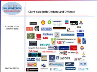
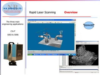
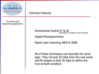
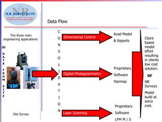
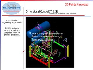
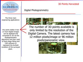
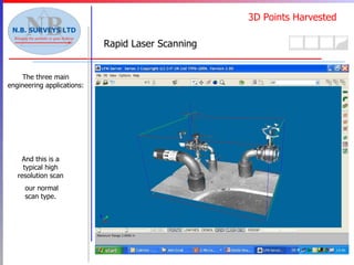
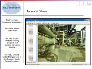
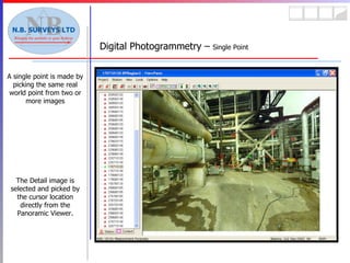
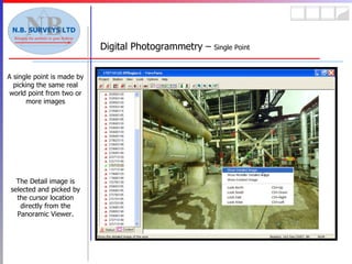
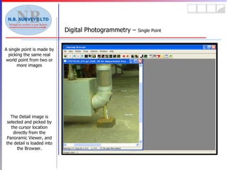
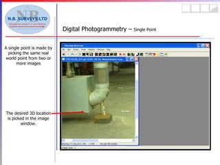
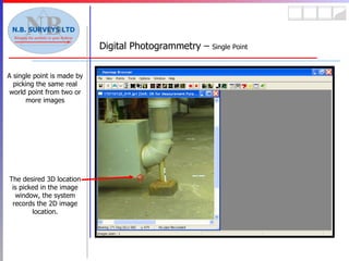
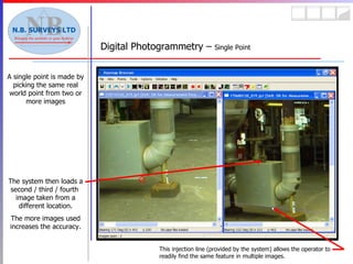
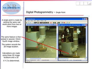
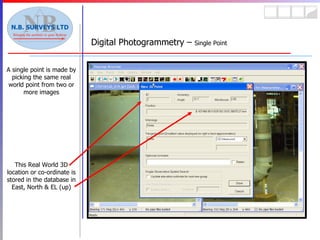
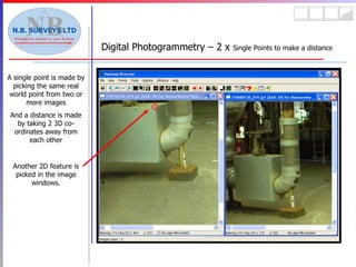
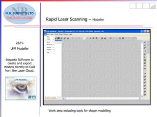
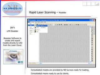
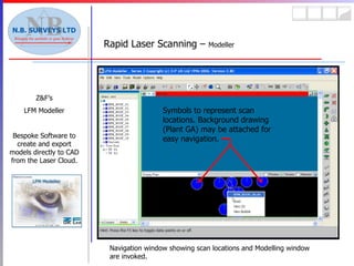
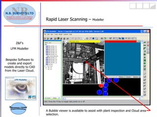
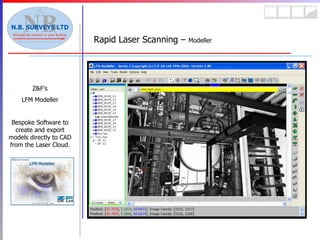
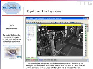
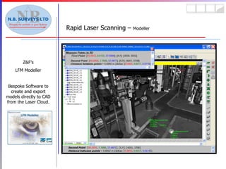
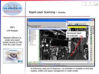
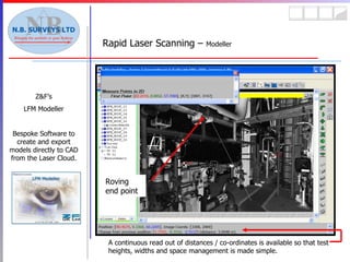
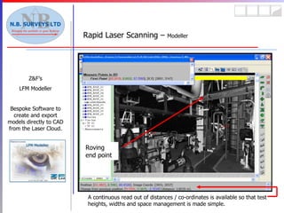
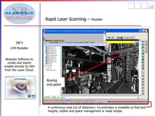
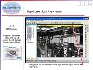
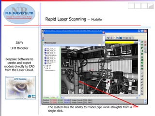
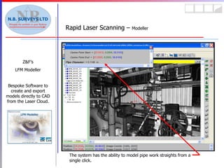
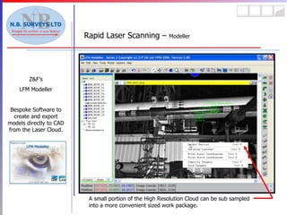
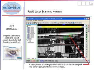
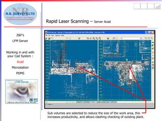
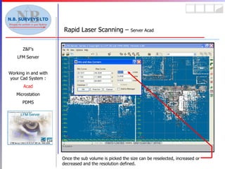
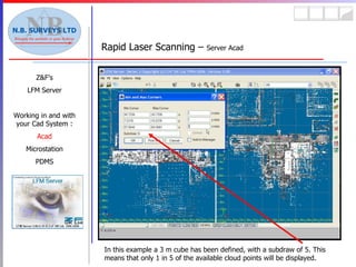
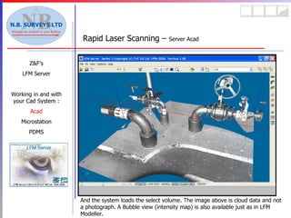
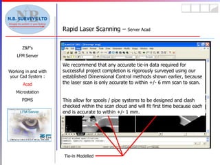
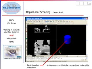
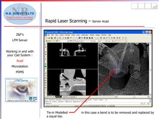
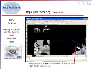
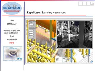
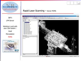
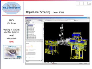
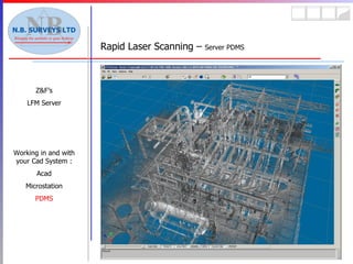
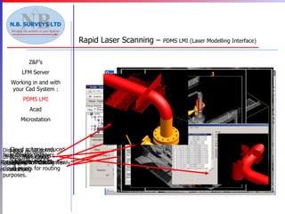
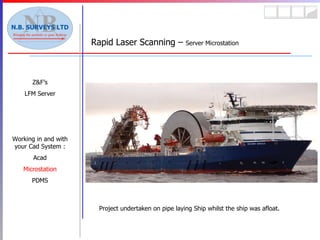
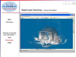
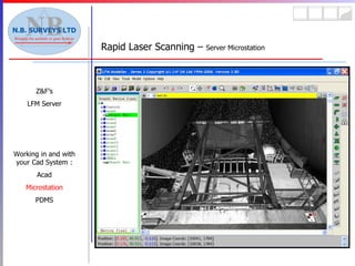
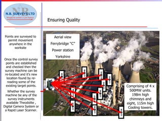
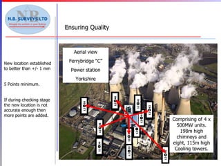
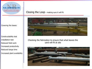
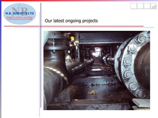
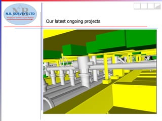
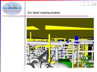
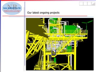
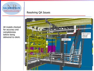
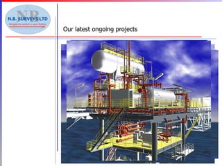
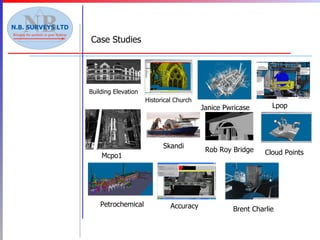
SlideShare a Scribd company logo
1 of 131
NB Surveys Ltd 182 Market Street Aberdeen SCOTLAND AB11 5PQ Tel: 01224 212324 Fax: 01224 212306 NB Surveys Limited - founded 25 years ago in 1982. Servicing Onshore & Offshore Oil & Gas markets around the world.  since 1988 Offices in: Aberdeen  Stirling  Teesside Brunei  Malaysia  Thailand Tuesday 1 st  October 13:00 Hours Presentation for Ramon Kirpalaney by Ged Hind Business Development Manager
The format of this presentation is a fixed PowerPoint presentation with an interactive software session at the end. This fixed presentation portion will last 40-45 minutes. Please any questions as we go through the presentation.
Examples of our customer base: Client base both Onshore and Offshore And new clients: Fairhursts
Equipment for both Onshore and Offshore Equipment used to form the complete solution: Construction Engineering Global Positioning System (GPS) Topographic Surveys Hydrographic Surveys Monitoring Building Surveys Boundary Disputes Dimensional Control Digital Photogrammetry Rapid Laser Scanning Construction Engineering Global Positioning System (GPS) Topographic Surveys Hydrographic Surveys Monitoring Building Surveys Boundary Disputes Dimensional Control Digital Photogrammetry Rapid Laser Scanning
Total Station Theodolites  (+/- 1 mm or better)  15 Off Total Station Theodolites  (+/- 2 mm or Better)  12 Off GPS Systems  (+/- 10 mm XY & 20 mm  Z or better)  4 Off Levels (Various including Machine Levels)  13 Off Laser Points (Co-axial for Theodolite)  1 Off Digital High Resolution Cameras  2 Off Rapid Laser Scanners (3 Cabled + 3 Battery)  6 Off  Equipment Summary:
Deliverable types of the complete solution: What you get Construction Engineering Global Positioning System (GPS) Topographic Surveys Hydrographic Surveys Monitoring Building Surveys Boundary Disputes Dimensional Control Digital Photogrammetry Rapid Laser Scanning Construction Engineering Global Positioning System (GPS) Topographic Surveys Hydrographic Surveys Boundary Disputes Monitoring Dimensional Control Digital Photogrammetry Rapid Laser Scanning Building Surveys
The three main engineering applications: Dimensional Control Intersection X,Y,Z  to +/-  Microns X,Y,Z  to +/-  Microns X,Y,Z  to +/-  Microns Dimensional Control by  Intersection . Accurate to within machine tolerances. Calibrated   Relationship Dimensional   Control IT & IR  Overview Intersection, InfraRed & Laser Distomat
The three main engineering applications: Dimensional Control InfraRed Dimensional Control by  InfraRed . Accurate to better than +/- 1 mm. E,N,U in mm However, if you can not access the area for prism locating then there is a non prism solution. Dimensional   Control IT & IR  Overview Intersection, InfraRed & Laser Distomat
The three main engineering applications: Dimensional Control Laser Distomat Dimensional Control by  Laser Distomat . Accurate to better than +/- 3 mm. E,N,U in mm Dimensional   Control IT & IR  Overview Intersection, InfraRed & Laser Distomat
Digital Photogrammetry  Overview The three main engineering applications: Proof Of Concept This large tessellated image created from all Eight radial stills forms a  panoramic view for easy and effective visualisation of the plant area. Aerial view Ferrybridge “C” Power station Yorkshire Comprising of 4 x 500MW units. 198m high chimneys and eight, 115m high Cooling towers. Panoramic Viewer Demonstration
Panoramic Viewer  Overview The three main engineering applications: The Red / Green & Amber triangles seen in the Images indicate Camera locations. Panoramic Viewer by Hazmap An easy to user utility for viewing the plant and jumping from area to area.
Rapid Laser Scanning  Overview The three main engineering applications: Z & F 5003 & 5006 Panoramic Viewer Demonstration
All of these techniques use basically the same logic. They harvest 3D data from the real world and fit shapes to that 3D data to define the true as-built condition.   Digital Photogrammetry Rapid Laser Scanning 5003 & 5006 Common Features The three main engineering applications: Dimensional   Control IT & IR Intersection, InfraRed & Laser Distomat
3D D A T A F R O M S I T E Data Flow The three main engineering applications: Site Survey C O N S O L I D A T I O N Dimensional   Control Acad Model & Reports Digital Photogrammetry Laser Scanning Proprietary  Software Hazmap Proprietary  Software LFM M / S Client based model effort resulting in clients low cost solution. NB Surveys Model build at extra cost. or
3D Points Harvested The three main engineering applications: And the tie-in and routing models are completed ready for drawing production. That is the end of the Dimensional Control section and now onto  Digital Photogrammetry Dimensional   Control IT & IR Intersection, InfraRed & Laser Distomat Points are surveyed on site together with flange Tie-in measurements to allow production of model / drawing / isometrics. And the data is logged thus:- Nominated Tie-in points for both pipe and steel systems are determined : The Tie-in Data and nominated route data is transferred from the record sheets into Cad.
3D Points Harvested Digital Photogrammetry The three main engineering applications: Any point visible in two or more Digital Images can be digitised and converted to 3D via the Photogrammetry algorithms and then used to feed shape fitting and CAD software to represent the As-Built condition of the surveyed plant.  The number of 3D points available is only limited by the resolution of the Digital Camera. The latest camera has 12 million pixels/image or 96 million pixels/panoramic view.
3D Points Harvested Rapid Laser Scanning The three main engineering applications: Scanned Cloud point pitch Ultrahigh  Superhigh   High  Middle  Preview 10m  1.6mm  3.1mm   6.3mm  12.6mm  50.3mm 25m  3.9mm  7.9mm   15.7mm  31.4mm  125.7mm 50m  7.9mm  15.7mm   31.4mm  62.8mm  251.3mm 80m  12.6mm  25.1mm   50.3mm  100.5mm  402.1mm Scantime  26.5 min  6.6 min   3.3 min  1.6 min  24 sec Filesize  2.7 GB  694 MB   173 MB  43 MB  2 MB This system measures and stores points as a “cloud” each point having a xyz location and an intensity value. This is a typical low resolution cloud. Shown in Aveva’s LMI module. Each Laser Scan resolution is varied to suit the plant conditions and accuracy required.  And this is a typical high resolution scan our normal scan type.
And now for Digital Photogrammetry in much more detail.
Panoramic Viewer The three main engineering applications: The Red / Green & Amber triangles seen in the Images indicate Camera locations. Panoramic Viewer by Hazmap An easy to user utility for viewing the plant and jumping from area to area.
Digital Photogrammetry –  Single Point A single point is made by picking the same real world point from two or more images The Detail image is selected and picked by the cursor location directly from the Panoramic Viewer.
Digital Photogrammetry –  Single Point A single point is made by picking the same real world point from two or more images The Detail image is selected and picked by the cursor location directly from the Panoramic Viewer, and the detail is loaded into the Browser.
Digital Photogrammetry –  Single Point A single point is made by picking the same real world point from two or more images The desired 3D location is picked in the image window.
Digital Photogrammetry –  Single Point A single point is made by picking the same real world point from two or more images The desired 3D location is picked in the image window, the system records the 2D image location.
Digital Photogrammetry –  Single Point A single point is made by picking the same real world point from two or more images The system then loads a second / third / fourth  image taken from a different location. The more images used increases the accuracy. This injection line (provided by the system) allows the operator to readily find the same feature in multiple images.
Digital Photogrammetry –  Single Point A single point is made by picking the same real world point from two or more images The same feature is then picked in second / third / fourth image window. The system records the 2D image location. Calculations are made using these 2D image locations and a 3D X Y Z is determined.
Digital Photogrammetry –  Single Point A single point is made by picking the same real world point from two or more images This Real World 3D location or co-ordinate is stored in the database in East, North & EL (up)
Digital Photogrammetry – 2 x  Single Points to make a distance A single point is made by picking the same real world point from two or more images And a distance is made by taking 2 3D co-ordinates away from each other Another 2D feature is picked in the image windows.
Digital Photogrammetry – 2 x  Single Points to make a distance A single point is made by picking the same real world point from two or more images And a distance is made by taking 2 3D co-ordinates away from each other A new 3D location is determined and stored. Then the two 3D locations are taken away to produce a distance measurement.
Digital Photogrammetry –  Pipe Centre Line by Tangents A pipe centre line is measured by truly picking two tangential surfaces either side of the pipe. The data calculated is the pipe diameter and the centre line location. This data is then automatically store in the database for use later. This digital set square is aligned so that the true diameter of the pipe is described by the normal to the tangential line.
Digital Photogrammetry –  Pipe Centre Line by Tangents A pipe centre line is measured by truly picking two tangential surfaces either side of the pipe. The data calculated is the pipe diameter and the centre line location. This data is then automatically store in the database for use later. THUS
Digital Photogrammetry –  Pipe Centre Line by Tangents A pipe centre line is measured by truly picking two tangential surfaces either side of the pipe. The data calculated is the pipe diameter and the centre line location. This data is then automatically store in the database for use later. And by using the injection line the same diameter is picked in other images.
Viewpipe by Hazmap An easy to use utility for routing orthogonal Cad Friendly pipe systems. The assumptions made are that the Rapidly Routed Pipes are to represent the As-Designed route, between accurate As-Built (+/- 1 mm) Tie-ins. Detailed in your Cad Package and data from the Tie-in report. Digital Photogrammetry –  Pipe Rapid Routing
Viewpipe by Hazmap Digital Photogrammetry –  Pipe Rapid Routing Existing 3D stored points are loaded into images from database. These were measured using the tangential pipe tool shown earlier. The 3D location and pipe OD in mm are recovered from the stored data.
Viewpipe by Hazmap Digital Photogrammetry –  Pipe Rapid Routing Existing 3D stored points are loaded into images from database. A point is nominated as the start point for the pipe route.
Viewpipe by Hazmap Digital Photogrammetry –  Pipe Rapid Routing Existing 3D stored points are loaded into images from database. A point is nominated as the start point for the pipe route. A new route is selected. In the up direction.
Viewpipe by Hazmap Digital Photogrammetry –  Pipe Rapid Routing Existing 3D stored points are loaded into images from database. A going up pipe is fitted by the system using the stored data. However, we need to now set the leave direction.
Viewpipe by Hazmap Digital Photogrammetry –  Pipe Rapid Routing Existing 3D stored points are loaded into images from database. Leave direction is now set. Now we can drag the leave pipe upwards until the horizontal (Green) portion is in the correct location.
Viewpipe by Hazmap Digital Photogrammetry –  Pipe Rapid Routing The bend is now correctly located. The bend is locked and the next portion of pipe is routed. The assumption is that the next item is also a bend.
Viewpipe by Hazmap Digital Photogrammetry –  Pipe Rapid Routing This new portion is simply dragged over the image to describe the route.
Viewpipe by Hazmap Digital Photogrammetry –  Pipe Rapid Routing When no more of the route can be seen the system is tasked to find more images of the nominated item (Bend in this case)
Viewpipe by Hazmap Digital Photogrammetry –  Pipe Rapid Routing The system uses the 3D location of the selected item to search the entire database for images that show that 3D location. These selected images are presented as Thumbnails for user selection.
Viewpipe by Hazmap Digital Photogrammetry –  Pipe Rapid Routing A new routing window is selected from the thumbnails and routing continued.
Viewpipe by Hazmap Digital Photogrammetry –  Pipe Rapid Routing A new routing window is selected from the thumbnails and routing continued. When routing complete the pipe is exported for use in the nominated CAD system: PDMS ACAD Microstation
Spatial Search  by Hazmap An easy to use utility for Searching for either 3D points or Cad Elements, especially useful in asset management (Vnet). It was used during Rapid Routing for finding the next image along the pipe route. Digital Photogrammetry –  Spatial Search for 3D points / items Any CAD item of nominated 3D point can be used as the search criteria. In this case a 3D point measured earlier is to be used.
Spatial Search  by Hazmap An easy to use utility for Searching for either 3D points or Cad Elements, especially useful in asset management (Vnet). It was used during Rapid Routing for finding the next image along the pipe route. Digital Photogrammetry –  Spatial Search for 3D points / items The system searches all the database an display images showing the 3D co-ordinate for the user to action.
Digital Photogrammetry –  Interfaces with CAD PDMS Interface Vnet Interface for Hazmap Two-way communication with PDMS Two-way communication with PDMS
Digital Photogrammetry –  Asset Management   Image Captured from Woodside’s  Vnet Implementation  Australia: PDMS Interface Vnet Interface for Hazmap
Digital Photogrammetry  ViewPipe with model overlay CAD system interface and viewing As-Built or As-Designed model in-conjunction with the plant data. Used to record the As-Built condition and / or the new detailed design data within the plant environment. New items can be test fitted into the real world to establish if there are any clash problems.
Digital Photogrammetry -  Examples Some typical results produced using Hazmap for clash detection in conjunction with Aveva’s PDMS design module New Items Existing fire hose cabinet / deluge cabinet will need to be relocated. Existing eyewash station may require relocation Existing fire hose cabinet / deluge cabinet will need to be relocated. Existing eyewash station may require relocation
Some typical results produced using Hazmap for clash detection in conjunction with Aveva’s PDMS design module. Digital Photogrammetry -  Examples New items Clash between new pipe and existing Instrument Cabinet. Clash between new pipe and existing Instrument Cabinet.
And now for Rapid Laser Scanning in much more detail.
Rapid Laser Scanning –  Modeller Z&F’s LFM Modeller Bespoke Software to create and export models directly to CAD from the Laser Cloud. Work area including tools for shape modelling
Rapid Laser Scanning –  Modeller Z&F’s LFM Modeller Bespoke Software to create and export models directly to CAD from the Laser Cloud. Consolidated models are provided by NB Surveys ready for loading. Consolidated means ready to use by clients.
Rapid Laser Scanning –  Modeller Z&F’s LFM Modeller Bespoke Software to create and export models directly to CAD from the Laser Cloud. Navigation window showing scan locations and Modelling window are invoked. Symbols to represent scan locations. Background drawing (Plant GA) may be attached for easy navigation.
Rapid Laser Scanning –  Modeller Z&F’s LFM Modeller Bespoke Software to create and export models directly to CAD from the Laser Cloud. A Bubble viewer is available to assist with plant inspection and Cloud area selection. Panoramic Viewer Demonstration
Rapid Laser Scanning –  Modeller Z&F’s LFM Modeller Bespoke Software to create and export models directly to CAD from the Laser Cloud.
Rapid Laser Scanning –  Modeller Z&F’s LFM Modeller Bespoke Software to create and export models directly to CAD from the Laser Cloud. This Bubble view is explicitly linked to the consolidated Cloud data, so that you can probe this image and extract true accurate 3D data such as 3D co-ordinates or measurements to within +/- 6 mm scan to scan.
Rapid Laser Scanning –  Modeller Z&F’s LFM Modeller Bespoke Software to create and export models directly to CAD from the Laser Cloud.
Rapid Laser Scanning –  Modeller Z&F’s LFM Modeller Bespoke Software to create and export models directly to CAD from the Laser Cloud. A continuous read out of distances / co-ordinates is available so that test heights, widths and space management is made simple. Anchored start co-ordinate
Rapid Laser Scanning –  Modeller Z&F’s LFM Modeller Bespoke Software to create and export models directly to CAD from the Laser Cloud. A continuous read out of distances / co-ordinates is available so that test heights, widths and space management is made simple. Roving end point
Rapid Laser Scanning –  Modeller Z&F’s LFM Modeller Bespoke Software to create and export models directly to CAD from the Laser Cloud. The system has the ability to model pipe work straights from a single click.
Rapid Laser Scanning –  Modeller Z&F’s LFM Modeller Bespoke Software to create and export models directly to CAD from the Laser Cloud. The system has the ability to model pipe work straights from a single click, or two pipes and calculate Position, Diameter & Gap.
Rapid Laser Scanning –  Modeller Z&F’s LFM Modeller Bespoke Software to create and export models directly to CAD from the Laser Cloud. A small portion of the High Resolution Cloud can be sub sampled into a more convenient sized work package.
Rapid Laser Scanning –  Server Acad Z&F’s LFM Server Working in and with your Cad System : Acad Microstation PDMS Consolidated Cloud Data is provided by NB Surveys ready for loading. Consolidated means ready to use by clients.
Rapid Laser Scanning –  Server Acad Z&F’s LFM Server Working in and with your Cad System : Acad Microstation PDMS The system displays nominated geographical areas incorporating all the scans covering that area.
Rapid Laser Scanning –  Server Acad Z&F’s LFM Server Working in and with your Cad System : Acad Microstation PDMS Sub volumes are selected to reduce the size of the work area, this increases productivity, and allows clashing checking of existing plant.
Rapid Laser Scanning –  Server Acad Z&F’s LFM Server Working in and with your Cad System : Acad Microstation PDMS Once the sub volume is picked the size can be reselected, increased or decreased and the resolution defined.
Rapid Laser Scanning –  Server Acad Z&F’s LFM Server Working in and with your Cad System : Acad Microstation PDMS In this example a 3 m cube has been defined, with a subdraw of 5. This means that only 1 in 5 of the available cloud points will be displayed.
Rapid Laser Scanning –  Server Acad Z&F’s LFM Server Working in and with your Cad System : Acad Microstation PDMS And the system loads the select volume. The image above is cloud data and not a photograph. A Bubble view (intensity map) is also available just as in LFM Modeller.
Rapid Laser Scanning –  Server Acad Z&F’s LFM Server Working in and with your Cad System : Acad Microstation PDMS This is the Bubble view of the same volume. The scan footprint can easily be seen. This is the only part of a full sphere harvested during every scan.
Rapid Laser Scanning –  Server Acad Z&F’s LFM Server Working in and with your Cad System : Acad Microstation PDMS The 3D Cloud data can be rotated in just the same way as a 3D model. It is a 3D model made up of millions of 3D points with a location and intensity value.
Rapid Laser Scanning –  Server Acad Z&F’s LFM Server Working in and with your Cad System : Acad Microstation PDMS The current cloud view can be exported to various Cad packages.
Rapid Laser Scanning –  Server Acad Z&F’s LFM Server Working in and with your Cad System : Acad Microstation PDMS The Cad package will now load the current cloud view as a background model.
Rapid Laser Scanning –  Server Acad Z&F’s LFM Server Working in and with your Cad System : Acad Microstation PDMS The exact location / orientation of any tie-in points in then modelled directly from the Dimensional Control data that accompanies all site scans. This tie-in data is accurate to within +/- 1 mm.
Rapid Laser Scanning –  Server Acad Z&F’s LFM Server Working in and with your Cad System : Acad Microstation PDMS Tie-in Modelled We recommend that any accurate tie-in data required for successful project completion is rigorously surveyed using our established Dimensional Control methods shown earlier, because the laser scan is only accurate to within +/- 6 mm scan to scan. This allow for spools / pipe systems to be designed and clash checked within the scan cloud and will fit first time because each end is accurate to within +/- 1 mm.
Rapid Laser Scanning –  Server Acad Z&F’s LFM Server Working in and with your Cad System : Acad Microstation PDMS Tie-in Modelled  in this case a bend is to be removed and replaced by a equal tee.
Rapid Laser Scanning –  Server Acad Z&F’s LFM Server Working in and with your Cad System : Acad Microstation PDMS The new design is routed away from the Tie-in to suit project design requirements.
Rapid Laser Scanning –  Server Acad Z&F’s LFM Server Working in and with your Cad System : Acad Microstation PDMS The new design is routed away from the Tie-in to suit project design requirements. A clash check of these new design items against real world plant configuration can be undertaken at any time.
Rapid Laser Scanning –  Server Acad Z&F’s LFM Server Working in and with your Cad System : Acad Microstation PDMS A clash report is created and the clashes can be examined.
Rapid Laser Scanning –  Server Acad Z&F’s LFM Server Working in and with your Cad System : Acad Microstation PDMS The original selected volume can be increased if the design data has extended beyond the initial clash volume selection.
Rapid Laser Scanning –  Server Acad Z&F’s LFM Server Working in and with your Cad System : Acad Microstation PDMS The new selected volume is automatically updated for clash inspection.
Rapid Laser Scanning –  Server Acad Z&F’s LFM Server Working in and with your Cad System : Acad Microstation PDMS Real plant items that are going to be removed during a projects execution can be demolished from the cloud so that they do not clash with replacement items.
Rapid Laser Scanning –  Server PDMS Z&F’s LFM Server Working in and with your Cad System : Acad Microstation PDMS The same server software is also used to integrate into PDMS Cad package.
Rapid Laser Scanning –  Server PDMS Z&F’s LFM Server Working in and with your Cad System : Acad Microstation PDMS
Z&F’s LFM Server Working in and with your Cad System : Acad Microstation PDMS Rapid Laser Scanning –  Server PDMS
Z&F’s LFM Server Working in and with your Cad System : PDMS LMI Acad Microstation Rapid Laser Scanning –  PDMS LMI (Laser Modelling Interface) Distance & 3D points directly from cloud using LMI New Design graphics being displayed with cloud points for routing purposes. Rotated view showing newly routed Pipe Cloud volume reduced to limited routed volume for clash checking Results from Clasher  Close up view showing clashes
Z&F’s LFM Server Working in and with your Cad System : Acad Microstation PDMS Rapid Laser Scanning –  Server Microstation Project undertaken on pipe laying Ship whilst the ship was afloat.
Z&F’s LFM Server Working in and with your Cad System : Acad Microstation PDMS Rapid Laser Scanning –  Server Microstation
Points are surveyed to permit movement anywhere in the worksite Ensuring Quality   From this start location we can easily see all of these points covering most of the site. And so what we do is position the Theodolite here and survey uniquely number targets around the plant.  Incidentally these targets  are very useful during construction because they can be re-used by your construction contractor for installing the new items. Once the control survey points are established and checked then the survey machine can be re-located and it’s new location found by re-reading some of the existing target points. Whether the survey machine be any of the survey instruments available Theodolite , Digital Camera System or a Rapid Laser Scanner. Aerial view Ferrybridge “C” Power station Yorkshire Comprising of 4 x 500MW units. 198m high chimneys and eight, 115m high Cooling towers. 12  34 12  35 12  36 12  37 12  38 12  39 12  40 12  41 12  42 12  43 12  44 A start location is determined so that a major portion of the plant can be seen from one chosen start point location. For example here.
New location established to better than +/- 1 mm 5 Points minimum. If during checking stage the new location is not accurate enough then more points are added. Ensuring Quality   Aerial view Ferrybridge “C” Power station Yorkshire Comprising of 4 x 500MW units. 198m high chimneys and eight, 115m high Cooling towers. 12  34 12  35 12  36 12  37 12  38 12  39 12  40 12  41 12  42 12  44 12  43 12  34 12  35 12  36 12  37 12  38 12  39 12  40 12  41 12  42
Covering the bases: Checking the fabrication to ensure that what leaves the yard will fit at site Constructability test Installation test  Reduced field work Increased productivity Reduced barge time Increased plant availability   Closing the Loop  -  making sure it will fit
All three of these Survey Solutions bring you: ,[object Object],[object Object],[object Object],[object Object],[object Object],[object Object],[object Object],[object Object],[object Object],[object Object],[object Object],Reductions
Benefits ,[object Object],[object Object],[object Object],[object Object],[object Object],[object Object],[object Object],[object Object]
Cost Savings ,[object Object],[object Object],[object Object],[object Object],[object Object],[object Object],[object Object],[object Object],[object Object]
Our latest ongoing projects
Resolving QA Issues All models checked for accuracy and completeness before being delivered to client.
Our latest ongoing projects
Case Studies Janice Pwricase Building Elevation Historical Church Lpop Mcpo1 Petrochemical Cloud Points Skandi Accuracy Rob Roy Bridge Brent Charlie
Thank you for your attention. Any further questions? NB Surveys Ltd 182 Market Street Aberdeen SCOTLAND AB11 5PQ Tel: 01224 212324 Fax: 01224 212306 Tuesday 1 st  October 13:00 Hours Presentation for Ramon kirpalaney by Ged Hind Business Development Manager NB N.B. SURVEYS LTD Bringing the worksite to your desktop

More Related Content

What's hot

Automatic Real Time Auditorium Power Supply Control using Image Processing
Automatic Real Time Auditorium Power Supply Control using Image ProcessingAutomatic Real Time Auditorium Power Supply Control using Image Processing
Automatic Real Time Auditorium Power Supply Control using Image Processingidescitation
 
Video Surveillance Systems For Traffic Monitoring
Video Surveillance Systems For Traffic MonitoringVideo Surveillance Systems For Traffic Monitoring
Video Surveillance Systems For Traffic MonitoringMeridian Media
 
LiDAR in the Adverse Weather: Dust, Snow, Rain and Fog (2)
LiDAR in the Adverse Weather: Dust, Snow, Rain and Fog (2)LiDAR in the Adverse Weather: Dust, Snow, Rain and Fog (2)
LiDAR in the Adverse Weather: Dust, Snow, Rain and Fog (2)Yu Huang
 
Arpan pal roboticsensing_sw2015
Arpan pal roboticsensing_sw2015Arpan pal roboticsensing_sw2015
Arpan pal roboticsensing_sw2015Arpan Pal
 
Lidar in the adverse weather: dust, fog, snow and rain
Lidar in the adverse weather: dust, fog, snow and rainLidar in the adverse weather: dust, fog, snow and rain
Lidar in the adverse weather: dust, fog, snow and rainYu Huang
 
OpenStreetMap in 3D - current developments
OpenStreetMap in 3D - current developmentsOpenStreetMap in 3D - current developments
OpenStreetMap in 3D - current developmentsvirtualcitySYSTEMS GmbH
 
Immersive 3 d visualization of remote sensing data
Immersive 3 d visualization of remote sensing dataImmersive 3 d visualization of remote sensing data
Immersive 3 d visualization of remote sensing datasipij
 
The flow of baseline estimation using a single omnidirectional camera
The flow of baseline estimation using a single omnidirectional cameraThe flow of baseline estimation using a single omnidirectional camera
The flow of baseline estimation using a single omnidirectional cameraTELKOMNIKA JOURNAL
 
Bl32821831
Bl32821831Bl32821831
Bl32821831IJMER
 
“Efficient Deep Learning for 3D Point Cloud Understanding,” a Presentation fr...
“Efficient Deep Learning for 3D Point Cloud Understanding,” a Presentation fr...“Efficient Deep Learning for 3D Point Cloud Understanding,” a Presentation fr...
“Efficient Deep Learning for 3D Point Cloud Understanding,” a Presentation fr...Edge AI and Vision Alliance
 
Mobile Based Application to Scan the Number Plate and To Verify the Owner Det...
Mobile Based Application to Scan the Number Plate and To Verify the Owner Det...Mobile Based Application to Scan the Number Plate and To Verify the Owner Det...
Mobile Based Application to Scan the Number Plate and To Verify the Owner Det...inventionjournals
 
IRJET- Proposed Design for 3D Map Generation using UAV
IRJET- Proposed Design for 3D Map Generation using UAVIRJET- Proposed Design for 3D Map Generation using UAV
IRJET- Proposed Design for 3D Map Generation using UAVIRJET Journal
 
An Open Source solution for Three-Dimensional documentation: archaeological a...
An Open Source solution for Three-Dimensional documentation: archaeological a...An Open Source solution for Three-Dimensional documentation: archaeological a...
An Open Source solution for Three-Dimensional documentation: archaeological a...Giulio Bigliardi
 
IRJET- SEPD Technique for Removal of Salt and Pepper Noise in Digital Images
IRJET- SEPD Technique for Removal of Salt and Pepper Noise in Digital ImagesIRJET- SEPD Technique for Removal of Salt and Pepper Noise in Digital Images
IRJET- SEPD Technique for Removal of Salt and Pepper Noise in Digital ImagesIRJET Journal
 
Traffic control using image processing
Traffic control using image processingTraffic control using image processing
Traffic control using image processingChirag Panchal
 
COMPLETE END-TO-END LOW COST SOLUTION TO A 3D SCANNING SYSTEM WITH INTEGRATED...
COMPLETE END-TO-END LOW COST SOLUTION TO A 3D SCANNING SYSTEM WITH INTEGRATED...COMPLETE END-TO-END LOW COST SOLUTION TO A 3D SCANNING SYSTEM WITH INTEGRATED...
COMPLETE END-TO-END LOW COST SOLUTION TO A 3D SCANNING SYSTEM WITH INTEGRATED...ijcsit
 
CE6404 ANNA UNIVERSITY Unit iii total station surveying
CE6404 ANNA UNIVERSITY Unit iii total station surveyingCE6404 ANNA UNIVERSITY Unit iii total station surveying
CE6404 ANNA UNIVERSITY Unit iii total station surveyingDr Gopikrishnan T
 

What's hot (19)

Automatic Real Time Auditorium Power Supply Control using Image Processing
Automatic Real Time Auditorium Power Supply Control using Image ProcessingAutomatic Real Time Auditorium Power Supply Control using Image Processing
Automatic Real Time Auditorium Power Supply Control using Image Processing
 
Video Surveillance Systems For Traffic Monitoring
Video Surveillance Systems For Traffic MonitoringVideo Surveillance Systems For Traffic Monitoring
Video Surveillance Systems For Traffic Monitoring
 
LiDAR in the Adverse Weather: Dust, Snow, Rain and Fog (2)
LiDAR in the Adverse Weather: Dust, Snow, Rain and Fog (2)LiDAR in the Adverse Weather: Dust, Snow, Rain and Fog (2)
LiDAR in the Adverse Weather: Dust, Snow, Rain and Fog (2)
 
Arpan pal roboticsensing_sw2015
Arpan pal roboticsensing_sw2015Arpan pal roboticsensing_sw2015
Arpan pal roboticsensing_sw2015
 
Lidar in the adverse weather: dust, fog, snow and rain
Lidar in the adverse weather: dust, fog, snow and rainLidar in the adverse weather: dust, fog, snow and rain
Lidar in the adverse weather: dust, fog, snow and rain
 
OpenStreetMap in 3D - current developments
OpenStreetMap in 3D - current developmentsOpenStreetMap in 3D - current developments
OpenStreetMap in 3D - current developments
 
Immersive 3 d visualization of remote sensing data
Immersive 3 d visualization of remote sensing dataImmersive 3 d visualization of remote sensing data
Immersive 3 d visualization of remote sensing data
 
The flow of baseline estimation using a single omnidirectional camera
The flow of baseline estimation using a single omnidirectional cameraThe flow of baseline estimation using a single omnidirectional camera
The flow of baseline estimation using a single omnidirectional camera
 
Traffic controller
Traffic controllerTraffic controller
Traffic controller
 
Bl32821831
Bl32821831Bl32821831
Bl32821831
 
“Efficient Deep Learning for 3D Point Cloud Understanding,” a Presentation fr...
“Efficient Deep Learning for 3D Point Cloud Understanding,” a Presentation fr...“Efficient Deep Learning for 3D Point Cloud Understanding,” a Presentation fr...
“Efficient Deep Learning for 3D Point Cloud Understanding,” a Presentation fr...
 
Mobile Based Application to Scan the Number Plate and To Verify the Owner Det...
Mobile Based Application to Scan the Number Plate and To Verify the Owner Det...Mobile Based Application to Scan the Number Plate and To Verify the Owner Det...
Mobile Based Application to Scan the Number Plate and To Verify the Owner Det...
 
IRJET- Proposed Design for 3D Map Generation using UAV
IRJET- Proposed Design for 3D Map Generation using UAVIRJET- Proposed Design for 3D Map Generation using UAV
IRJET- Proposed Design for 3D Map Generation using UAV
 
An Open Source solution for Three-Dimensional documentation: archaeological a...
An Open Source solution for Three-Dimensional documentation: archaeological a...An Open Source solution for Three-Dimensional documentation: archaeological a...
An Open Source solution for Three-Dimensional documentation: archaeological a...
 
IRJET- SEPD Technique for Removal of Salt and Pepper Noise in Digital Images
IRJET- SEPD Technique for Removal of Salt and Pepper Noise in Digital ImagesIRJET- SEPD Technique for Removal of Salt and Pepper Noise in Digital Images
IRJET- SEPD Technique for Removal of Salt and Pepper Noise in Digital Images
 
Traffic control using image processing
Traffic control using image processingTraffic control using image processing
Traffic control using image processing
 
Survey 1 (project overview)
Survey 1 (project overview)Survey 1 (project overview)
Survey 1 (project overview)
 
COMPLETE END-TO-END LOW COST SOLUTION TO A 3D SCANNING SYSTEM WITH INTEGRATED...
COMPLETE END-TO-END LOW COST SOLUTION TO A 3D SCANNING SYSTEM WITH INTEGRATED...COMPLETE END-TO-END LOW COST SOLUTION TO A 3D SCANNING SYSTEM WITH INTEGRATED...
COMPLETE END-TO-END LOW COST SOLUTION TO A 3D SCANNING SYSTEM WITH INTEGRATED...
 
CE6404 ANNA UNIVERSITY Unit iii total station surveying
CE6404 ANNA UNIVERSITY Unit iii total station surveyingCE6404 ANNA UNIVERSITY Unit iii total station surveying
CE6404 ANNA UNIVERSITY Unit iii total station surveying
 

Similar to Rapid Laser Scanning the process

3D Scanners and their Economic Feasibility
3D Scanners and their Economic Feasibility3D Scanners and their Economic Feasibility
3D Scanners and their Economic FeasibilityJeffrey Funk
 
3D Image visualization
3D Image visualization3D Image visualization
3D Image visualizationalok ray
 
Total station and its application to civil engineering
Total station and its application to civil engineeringTotal station and its application to civil engineering
Total station and its application to civil engineeringTushar Dholakia
 
高解析度面板瑕疵檢測
高解析度面板瑕疵檢測高解析度面板瑕疵檢測
高解析度面板瑕疵檢測CHENHuiMei
 
Arindam batabyal literature reviewpresentation
Arindam batabyal literature reviewpresentationArindam batabyal literature reviewpresentation
Arindam batabyal literature reviewpresentationArindam Batabyal
 
Total station, digital self leveling levels,
Total station, digital self leveling levels,Total station, digital self leveling levels,
Total station, digital self leveling levels,Darshil Vekaria
 
Real time-image-processing-applied-to-traffic-queue-detection-algorithm
Real time-image-processing-applied-to-traffic-queue-detection-algorithmReal time-image-processing-applied-to-traffic-queue-detection-algorithm
Real time-image-processing-applied-to-traffic-queue-detection-algorithmajayrampelli
 
Photogrammetry Demo
Photogrammetry DemoPhotogrammetry Demo
Photogrammetry DemoWebs Now
 
Different Methodologies for Indian License Plate Detection
Different Methodologies for Indian License Plate DetectionDifferent Methodologies for Indian License Plate Detection
Different Methodologies for Indian License Plate DetectionIRJET Journal
 
From Sense to Print: Towards Automatic 3D Printing from 3D Sensing Devices
From Sense to Print: Towards Automatic 3D Printing from 3D Sensing DevicesFrom Sense to Print: Towards Automatic 3D Printing from 3D Sensing Devices
From Sense to Print: Towards Automatic 3D Printing from 3D Sensing Devicestoukaigi
 
Unit 3 machine vision
Unit 3 machine vision Unit 3 machine vision
Unit 3 machine vision rknatarajan
 

Similar to Rapid Laser Scanning the process (20)

Photogrammetry 1.
Photogrammetry 1.Photogrammetry 1.
Photogrammetry 1.
 
3D Scanners and their Economic Feasibility
3D Scanners and their Economic Feasibility3D Scanners and their Economic Feasibility
3D Scanners and their Economic Feasibility
 
3D Image visualization
3D Image visualization3D Image visualization
3D Image visualization
 
EN_3DLS_Oil_Gas_Offshore
EN_3DLS_Oil_Gas_OffshoreEN_3DLS_Oil_Gas_Offshore
EN_3DLS_Oil_Gas_Offshore
 
Total station and its application to civil engineering
Total station and its application to civil engineeringTotal station and its application to civil engineering
Total station and its application to civil engineering
 
高解析度面板瑕疵檢測
高解析度面板瑕疵檢測高解析度面板瑕疵檢測
高解析度面板瑕疵檢測
 
Arindam batabyal literature reviewpresentation
Arindam batabyal literature reviewpresentationArindam batabyal literature reviewpresentation
Arindam batabyal literature reviewpresentation
 
REVERSE ENGINEERING
REVERSE ENGINEERING REVERSE ENGINEERING
REVERSE ENGINEERING
 
Total station, digital self leveling levels,
Total station, digital self leveling levels,Total station, digital self leveling levels,
Total station, digital self leveling levels,
 
Instalatii_petroliere_03_EN
Instalatii_petroliere_03_ENInstalatii_petroliere_03_EN
Instalatii_petroliere_03_EN
 
Real time-image-processing-applied-to-traffic-queue-detection-algorithm
Real time-image-processing-applied-to-traffic-queue-detection-algorithmReal time-image-processing-applied-to-traffic-queue-detection-algorithm
Real time-image-processing-applied-to-traffic-queue-detection-algorithm
 
Photogrammetry Demo
Photogrammetry DemoPhotogrammetry Demo
Photogrammetry Demo
 
Different Methodologies for Indian License Plate Detection
Different Methodologies for Indian License Plate DetectionDifferent Methodologies for Indian License Plate Detection
Different Methodologies for Indian License Plate Detection
 
From Sense to Print: Towards Automatic 3D Printing from 3D Sensing Devices
From Sense to Print: Towards Automatic 3D Printing from 3D Sensing DevicesFrom Sense to Print: Towards Automatic 3D Printing from 3D Sensing Devices
From Sense to Print: Towards Automatic 3D Printing from 3D Sensing Devices
 
3D Laser Scaning FPSO Mystras
3D Laser Scaning FPSO Mystras3D Laser Scaning FPSO Mystras
3D Laser Scaning FPSO Mystras
 
3D Laser Scaning FPSO Mystras
3D Laser Scaning FPSO Mystras3D Laser Scaning FPSO Mystras
3D Laser Scaning FPSO Mystras
 
Unit 3 machine vision
Unit 3 machine vision Unit 3 machine vision
Unit 3 machine vision
 
Unit 3 machine vision
Unit 3 machine vision Unit 3 machine vision
Unit 3 machine vision
 
Machine Vision Systems And Applications
Machine Vision Systems And ApplicationsMachine Vision Systems And Applications
Machine Vision Systems And Applications
 
Total station
Total station Total station
Total station
 

Recently uploaded

Raj Nagar Extension Call Girls 9711199012 WhatsApp No, Delhi Escorts in Raj N...
Raj Nagar Extension Call Girls 9711199012 WhatsApp No, Delhi Escorts in Raj N...Raj Nagar Extension Call Girls 9711199012 WhatsApp No, Delhi Escorts in Raj N...
Raj Nagar Extension Call Girls 9711199012 WhatsApp No, Delhi Escorts in Raj N...ankitnayak356677
 
VIP Call Girls Service Kukatpally Hyderabad Call +91-8250192130
VIP Call Girls Service Kukatpally Hyderabad Call +91-8250192130VIP Call Girls Service Kukatpally Hyderabad Call +91-8250192130
VIP Call Girls Service Kukatpally Hyderabad Call +91-8250192130Suhani Kapoor
 
Dubai Call Girls Pro Domain O525547819 Call Girls Dubai Doux
Dubai Call Girls Pro Domain O525547819 Call Girls Dubai DouxDubai Call Girls Pro Domain O525547819 Call Girls Dubai Doux
Dubai Call Girls Pro Domain O525547819 Call Girls Dubai Douxkojalkojal131
 
NATA 2024 SYLLABUS, full syllabus explained in detail
NATA 2024 SYLLABUS, full syllabus explained in detailNATA 2024 SYLLABUS, full syllabus explained in detail
NATA 2024 SYLLABUS, full syllabus explained in detailDesigntroIntroducing
 
VIP Call Girls Service Mehdipatnam Hyderabad Call +91-8250192130
VIP Call Girls Service Mehdipatnam Hyderabad Call +91-8250192130VIP Call Girls Service Mehdipatnam Hyderabad Call +91-8250192130
VIP Call Girls Service Mehdipatnam Hyderabad Call +91-8250192130Suhani Kapoor
 
Design Portfolio - 2024 - William Vickery
Design Portfolio - 2024 - William VickeryDesign Portfolio - 2024 - William Vickery
Design Portfolio - 2024 - William VickeryWilliamVickery6
 
WAEC Carpentry and Joinery Past Questions
WAEC Carpentry and Joinery Past QuestionsWAEC Carpentry and Joinery Past Questions
WAEC Carpentry and Joinery Past QuestionsCharles Obaleagbon
 
Kieran Salaria Graphic Design PDF Portfolio
Kieran Salaria Graphic Design PDF PortfolioKieran Salaria Graphic Design PDF Portfolio
Kieran Salaria Graphic Design PDF Portfolioktksalaria
 
Chapter 19_DDA_TOD Policy_First Draft 2012.pdf
Chapter 19_DDA_TOD Policy_First Draft 2012.pdfChapter 19_DDA_TOD Policy_First Draft 2012.pdf
Chapter 19_DDA_TOD Policy_First Draft 2012.pdfParomita Roy
 
VIP Call Girls Service Bhagyanagar Hyderabad Call +91-8250192130
VIP Call Girls Service Bhagyanagar Hyderabad Call +91-8250192130VIP Call Girls Service Bhagyanagar Hyderabad Call +91-8250192130
VIP Call Girls Service Bhagyanagar Hyderabad Call +91-8250192130Suhani Kapoor
 
VIP Call Girl Amravati Aashi 8250192130 Independent Escort Service Amravati
VIP Call Girl Amravati Aashi 8250192130 Independent Escort Service AmravatiVIP Call Girl Amravati Aashi 8250192130 Independent Escort Service Amravati
VIP Call Girl Amravati Aashi 8250192130 Independent Escort Service AmravatiSuhani Kapoor
 
Cheap Rate Call girls Kalkaji 9205541914 shot 1500 night
Cheap Rate Call girls Kalkaji 9205541914 shot 1500 nightCheap Rate Call girls Kalkaji 9205541914 shot 1500 night
Cheap Rate Call girls Kalkaji 9205541914 shot 1500 nightDelhi Call girls
 
How to Be Famous in your Field just visit our Site
How to Be Famous in your Field just visit our SiteHow to Be Famous in your Field just visit our Site
How to Be Famous in your Field just visit our Sitegalleryaagency
 
Cosumer Willingness to Pay for Sustainable Bricks
Cosumer Willingness to Pay for Sustainable BricksCosumer Willingness to Pay for Sustainable Bricks
Cosumer Willingness to Pay for Sustainable Bricksabhishekparmar618
 
Revit Understanding Reference Planes and Reference lines in Revit for Family ...
Revit Understanding Reference Planes and Reference lines in Revit for Family ...Revit Understanding Reference Planes and Reference lines in Revit for Family ...
Revit Understanding Reference Planes and Reference lines in Revit for Family ...Narsimha murthy
 
The_Canvas_of_Creative_Mastery_Newsletter_April_2024_Version.pdf
The_Canvas_of_Creative_Mastery_Newsletter_April_2024_Version.pdfThe_Canvas_of_Creative_Mastery_Newsletter_April_2024_Version.pdf
The_Canvas_of_Creative_Mastery_Newsletter_April_2024_Version.pdfAmirYakdi
 
VIP College Call Girls Gorakhpur Bhavna 8250192130 Independent Escort Service...
VIP College Call Girls Gorakhpur Bhavna 8250192130 Independent Escort Service...VIP College Call Girls Gorakhpur Bhavna 8250192130 Independent Escort Service...
VIP College Call Girls Gorakhpur Bhavna 8250192130 Independent Escort Service...Suhani Kapoor
 
call girls in Harsh Vihar (DELHI) 🔝 >༒9953330565🔝 genuine Escort Service 🔝✔️✔️
call girls in Harsh Vihar (DELHI) 🔝 >༒9953330565🔝 genuine Escort Service 🔝✔️✔️call girls in Harsh Vihar (DELHI) 🔝 >༒9953330565🔝 genuine Escort Service 🔝✔️✔️
call girls in Harsh Vihar (DELHI) 🔝 >༒9953330565🔝 genuine Escort Service 🔝✔️✔️9953056974 Low Rate Call Girls In Saket, Delhi NCR
 
Cheap Rate Call girls Malviya Nagar 9205541914 shot 1500 night
Cheap Rate Call girls Malviya Nagar 9205541914 shot 1500 nightCheap Rate Call girls Malviya Nagar 9205541914 shot 1500 night
Cheap Rate Call girls Malviya Nagar 9205541914 shot 1500 nightDelhi Call girls
 

Recently uploaded (20)

Raj Nagar Extension Call Girls 9711199012 WhatsApp No, Delhi Escorts in Raj N...
Raj Nagar Extension Call Girls 9711199012 WhatsApp No, Delhi Escorts in Raj N...Raj Nagar Extension Call Girls 9711199012 WhatsApp No, Delhi Escorts in Raj N...
Raj Nagar Extension Call Girls 9711199012 WhatsApp No, Delhi Escorts in Raj N...
 
VIP Call Girls Service Kukatpally Hyderabad Call +91-8250192130
VIP Call Girls Service Kukatpally Hyderabad Call +91-8250192130VIP Call Girls Service Kukatpally Hyderabad Call +91-8250192130
VIP Call Girls Service Kukatpally Hyderabad Call +91-8250192130
 
Dubai Call Girls Pro Domain O525547819 Call Girls Dubai Doux
Dubai Call Girls Pro Domain O525547819 Call Girls Dubai DouxDubai Call Girls Pro Domain O525547819 Call Girls Dubai Doux
Dubai Call Girls Pro Domain O525547819 Call Girls Dubai Doux
 
NATA 2024 SYLLABUS, full syllabus explained in detail
NATA 2024 SYLLABUS, full syllabus explained in detailNATA 2024 SYLLABUS, full syllabus explained in detail
NATA 2024 SYLLABUS, full syllabus explained in detail
 
VIP Call Girls Service Mehdipatnam Hyderabad Call +91-8250192130
VIP Call Girls Service Mehdipatnam Hyderabad Call +91-8250192130VIP Call Girls Service Mehdipatnam Hyderabad Call +91-8250192130
VIP Call Girls Service Mehdipatnam Hyderabad Call +91-8250192130
 
Design Portfolio - 2024 - William Vickery
Design Portfolio - 2024 - William VickeryDesign Portfolio - 2024 - William Vickery
Design Portfolio - 2024 - William Vickery
 
WAEC Carpentry and Joinery Past Questions
WAEC Carpentry and Joinery Past QuestionsWAEC Carpentry and Joinery Past Questions
WAEC Carpentry and Joinery Past Questions
 
Kieran Salaria Graphic Design PDF Portfolio
Kieran Salaria Graphic Design PDF PortfolioKieran Salaria Graphic Design PDF Portfolio
Kieran Salaria Graphic Design PDF Portfolio
 
Call Girls Service Mukherjee Nagar @9999965857 Delhi 🫦 No Advance VVIP 🍎 SER...
Call Girls Service Mukherjee Nagar @9999965857 Delhi 🫦 No Advance  VVIP 🍎 SER...Call Girls Service Mukherjee Nagar @9999965857 Delhi 🫦 No Advance  VVIP 🍎 SER...
Call Girls Service Mukherjee Nagar @9999965857 Delhi 🫦 No Advance VVIP 🍎 SER...
 
Chapter 19_DDA_TOD Policy_First Draft 2012.pdf
Chapter 19_DDA_TOD Policy_First Draft 2012.pdfChapter 19_DDA_TOD Policy_First Draft 2012.pdf
Chapter 19_DDA_TOD Policy_First Draft 2012.pdf
 
VIP Call Girls Service Bhagyanagar Hyderabad Call +91-8250192130
VIP Call Girls Service Bhagyanagar Hyderabad Call +91-8250192130VIP Call Girls Service Bhagyanagar Hyderabad Call +91-8250192130
VIP Call Girls Service Bhagyanagar Hyderabad Call +91-8250192130
 
VIP Call Girl Amravati Aashi 8250192130 Independent Escort Service Amravati
VIP Call Girl Amravati Aashi 8250192130 Independent Escort Service AmravatiVIP Call Girl Amravati Aashi 8250192130 Independent Escort Service Amravati
VIP Call Girl Amravati Aashi 8250192130 Independent Escort Service Amravati
 
Cheap Rate Call girls Kalkaji 9205541914 shot 1500 night
Cheap Rate Call girls Kalkaji 9205541914 shot 1500 nightCheap Rate Call girls Kalkaji 9205541914 shot 1500 night
Cheap Rate Call girls Kalkaji 9205541914 shot 1500 night
 
How to Be Famous in your Field just visit our Site
How to Be Famous in your Field just visit our SiteHow to Be Famous in your Field just visit our Site
How to Be Famous in your Field just visit our Site
 
Cosumer Willingness to Pay for Sustainable Bricks
Cosumer Willingness to Pay for Sustainable BricksCosumer Willingness to Pay for Sustainable Bricks
Cosumer Willingness to Pay for Sustainable Bricks
 
Revit Understanding Reference Planes and Reference lines in Revit for Family ...
Revit Understanding Reference Planes and Reference lines in Revit for Family ...Revit Understanding Reference Planes and Reference lines in Revit for Family ...
Revit Understanding Reference Planes and Reference lines in Revit for Family ...
 
The_Canvas_of_Creative_Mastery_Newsletter_April_2024_Version.pdf
The_Canvas_of_Creative_Mastery_Newsletter_April_2024_Version.pdfThe_Canvas_of_Creative_Mastery_Newsletter_April_2024_Version.pdf
The_Canvas_of_Creative_Mastery_Newsletter_April_2024_Version.pdf
 
VIP College Call Girls Gorakhpur Bhavna 8250192130 Independent Escort Service...
VIP College Call Girls Gorakhpur Bhavna 8250192130 Independent Escort Service...VIP College Call Girls Gorakhpur Bhavna 8250192130 Independent Escort Service...
VIP College Call Girls Gorakhpur Bhavna 8250192130 Independent Escort Service...
 
call girls in Harsh Vihar (DELHI) 🔝 >༒9953330565🔝 genuine Escort Service 🔝✔️✔️
call girls in Harsh Vihar (DELHI) 🔝 >༒9953330565🔝 genuine Escort Service 🔝✔️✔️call girls in Harsh Vihar (DELHI) 🔝 >༒9953330565🔝 genuine Escort Service 🔝✔️✔️
call girls in Harsh Vihar (DELHI) 🔝 >༒9953330565🔝 genuine Escort Service 🔝✔️✔️
 
Cheap Rate Call girls Malviya Nagar 9205541914 shot 1500 night
Cheap Rate Call girls Malviya Nagar 9205541914 shot 1500 nightCheap Rate Call girls Malviya Nagar 9205541914 shot 1500 night
Cheap Rate Call girls Malviya Nagar 9205541914 shot 1500 night
 

Rapid Laser Scanning the process

  • 1. NB Surveys Ltd 182 Market Street Aberdeen SCOTLAND AB11 5PQ Tel: 01224 212324 Fax: 01224 212306 NB Surveys Limited - founded 25 years ago in 1982. Servicing Onshore & Offshore Oil & Gas markets around the world. since 1988 Offices in: Aberdeen Stirling Teesside Brunei Malaysia Thailand Tuesday 1 st October 13:00 Hours Presentation for Ramon Kirpalaney by Ged Hind Business Development Manager
  • 2. The format of this presentation is a fixed PowerPoint presentation with an interactive software session at the end. This fixed presentation portion will last 40-45 minutes. Please any questions as we go through the presentation.
  • 3. Examples of our customer base: Client base both Onshore and Offshore And new clients: Fairhursts
  • 4. Equipment for both Onshore and Offshore Equipment used to form the complete solution: Construction Engineering Global Positioning System (GPS) Topographic Surveys Hydrographic Surveys Monitoring Building Surveys Boundary Disputes Dimensional Control Digital Photogrammetry Rapid Laser Scanning Construction Engineering Global Positioning System (GPS) Topographic Surveys Hydrographic Surveys Monitoring Building Surveys Boundary Disputes Dimensional Control Digital Photogrammetry Rapid Laser Scanning
  • 5. Total Station Theodolites (+/- 1 mm or better) 15 Off Total Station Theodolites (+/- 2 mm or Better) 12 Off GPS Systems (+/- 10 mm XY & 20 mm Z or better) 4 Off Levels (Various including Machine Levels) 13 Off Laser Points (Co-axial for Theodolite) 1 Off Digital High Resolution Cameras 2 Off Rapid Laser Scanners (3 Cabled + 3 Battery) 6 Off Equipment Summary:
  • 6. Deliverable types of the complete solution: What you get Construction Engineering Global Positioning System (GPS) Topographic Surveys Hydrographic Surveys Monitoring Building Surveys Boundary Disputes Dimensional Control Digital Photogrammetry Rapid Laser Scanning Construction Engineering Global Positioning System (GPS) Topographic Surveys Hydrographic Surveys Boundary Disputes Monitoring Dimensional Control Digital Photogrammetry Rapid Laser Scanning Building Surveys
  • 7. The three main engineering applications: Dimensional Control Intersection X,Y,Z to +/- Microns X,Y,Z to +/- Microns X,Y,Z to +/- Microns Dimensional Control by Intersection . Accurate to within machine tolerances. Calibrated Relationship Dimensional Control IT & IR Overview Intersection, InfraRed & Laser Distomat
  • 8. The three main engineering applications: Dimensional Control InfraRed Dimensional Control by InfraRed . Accurate to better than +/- 1 mm. E,N,U in mm However, if you can not access the area for prism locating then there is a non prism solution. Dimensional Control IT & IR Overview Intersection, InfraRed & Laser Distomat
  • 9. The three main engineering applications: Dimensional Control Laser Distomat Dimensional Control by Laser Distomat . Accurate to better than +/- 3 mm. E,N,U in mm Dimensional Control IT & IR Overview Intersection, InfraRed & Laser Distomat
  • 10. Digital Photogrammetry Overview The three main engineering applications: Proof Of Concept This large tessellated image created from all Eight radial stills forms a panoramic view for easy and effective visualisation of the plant area. Aerial view Ferrybridge “C” Power station Yorkshire Comprising of 4 x 500MW units. 198m high chimneys and eight, 115m high Cooling towers. Panoramic Viewer Demonstration
  • 11. Panoramic Viewer Overview The three main engineering applications: The Red / Green & Amber triangles seen in the Images indicate Camera locations. Panoramic Viewer by Hazmap An easy to user utility for viewing the plant and jumping from area to area.
  • 12. Rapid Laser Scanning Overview The three main engineering applications: Z & F 5003 & 5006 Panoramic Viewer Demonstration
  • 13. All of these techniques use basically the same logic. They harvest 3D data from the real world and fit shapes to that 3D data to define the true as-built condition. Digital Photogrammetry Rapid Laser Scanning 5003 & 5006 Common Features The three main engineering applications: Dimensional Control IT & IR Intersection, InfraRed & Laser Distomat
  • 14. 3D D A T A F R O M S I T E Data Flow The three main engineering applications: Site Survey C O N S O L I D A T I O N Dimensional Control Acad Model & Reports Digital Photogrammetry Laser Scanning Proprietary Software Hazmap Proprietary Software LFM M / S Client based model effort resulting in clients low cost solution. NB Surveys Model build at extra cost. or
  • 15. 3D Points Harvested The three main engineering applications: And the tie-in and routing models are completed ready for drawing production. That is the end of the Dimensional Control section and now onto Digital Photogrammetry Dimensional Control IT & IR Intersection, InfraRed & Laser Distomat Points are surveyed on site together with flange Tie-in measurements to allow production of model / drawing / isometrics. And the data is logged thus:- Nominated Tie-in points for both pipe and steel systems are determined : The Tie-in Data and nominated route data is transferred from the record sheets into Cad.
  • 16. 3D Points Harvested Digital Photogrammetry The three main engineering applications: Any point visible in two or more Digital Images can be digitised and converted to 3D via the Photogrammetry algorithms and then used to feed shape fitting and CAD software to represent the As-Built condition of the surveyed plant. The number of 3D points available is only limited by the resolution of the Digital Camera. The latest camera has 12 million pixels/image or 96 million pixels/panoramic view.
  • 17. 3D Points Harvested Rapid Laser Scanning The three main engineering applications: Scanned Cloud point pitch Ultrahigh Superhigh High Middle Preview 10m 1.6mm 3.1mm 6.3mm 12.6mm 50.3mm 25m 3.9mm 7.9mm 15.7mm 31.4mm 125.7mm 50m 7.9mm 15.7mm 31.4mm 62.8mm 251.3mm 80m 12.6mm 25.1mm 50.3mm 100.5mm 402.1mm Scantime 26.5 min 6.6 min 3.3 min 1.6 min 24 sec Filesize 2.7 GB 694 MB 173 MB 43 MB 2 MB This system measures and stores points as a “cloud” each point having a xyz location and an intensity value. This is a typical low resolution cloud. Shown in Aveva’s LMI module. Each Laser Scan resolution is varied to suit the plant conditions and accuracy required. And this is a typical high resolution scan our normal scan type.
  • 18. And now for Digital Photogrammetry in much more detail.
  • 19. Panoramic Viewer The three main engineering applications: The Red / Green & Amber triangles seen in the Images indicate Camera locations. Panoramic Viewer by Hazmap An easy to user utility for viewing the plant and jumping from area to area.
  • 20. Digital Photogrammetry – Single Point A single point is made by picking the same real world point from two or more images The Detail image is selected and picked by the cursor location directly from the Panoramic Viewer.
  • 21. Digital Photogrammetry – Single Point A single point is made by picking the same real world point from two or more images The Detail image is selected and picked by the cursor location directly from the Panoramic Viewer.
  • 22. Digital Photogrammetry – Single Point A single point is made by picking the same real world point from two or more images The Detail image is selected and picked by the cursor location directly from the Panoramic Viewer, and the detail is loaded into the Browser.
  • 23. Digital Photogrammetry – Single Point A single point is made by picking the same real world point from two or more images The desired 3D location is picked in the image window.
  • 24. Digital Photogrammetry – Single Point A single point is made by picking the same real world point from two or more images The desired 3D location is picked in the image window, the system records the 2D image location.
  • 25. Digital Photogrammetry – Single Point A single point is made by picking the same real world point from two or more images The system then loads a second / third / fourth image taken from a different location. The more images used increases the accuracy. This injection line (provided by the system) allows the operator to readily find the same feature in multiple images.
  • 26. Digital Photogrammetry – Single Point A single point is made by picking the same real world point from two or more images The same feature is then picked in second / third / fourth image window. The system records the 2D image location. Calculations are made using these 2D image locations and a 3D X Y Z is determined.
  • 27. Digital Photogrammetry – Single Point A single point is made by picking the same real world point from two or more images This Real World 3D location or co-ordinate is stored in the database in East, North & EL (up)
  • 28. Digital Photogrammetry – 2 x Single Points to make a distance A single point is made by picking the same real world point from two or more images And a distance is made by taking 2 3D co-ordinates away from each other Another 2D feature is picked in the image windows.
  • 29. Digital Photogrammetry – 2 x Single Points to make a distance A single point is made by picking the same real world point from two or more images And a distance is made by taking 2 3D co-ordinates away from each other Another 2D feature is picked in the image windows.
  • 30. Digital Photogrammetry – 2 x Single Points to make a distance A single point is made by picking the same real world point from two or more images And a distance is made by taking 2 3D co-ordinates away from each other A new 3D location is determined and stored. Then the two 3D locations are taken away to produce a distance measurement.
  • 31. Digital Photogrammetry – Pipe Centre Line by Tangents A pipe centre line is measured by truly picking two tangential surfaces either side of the pipe. The data calculated is the pipe diameter and the centre line location. This data is then automatically store in the database for use later. This digital set square is aligned so that the true diameter of the pipe is described by the normal to the tangential line.
  • 32. Digital Photogrammetry – Pipe Centre Line by Tangents A pipe centre line is measured by truly picking two tangential surfaces either side of the pipe. The data calculated is the pipe diameter and the centre line location. This data is then automatically store in the database for use later. THUS
  • 33. Digital Photogrammetry – Pipe Centre Line by Tangents A pipe centre line is measured by truly picking two tangential surfaces either side of the pipe. The data calculated is the pipe diameter and the centre line location. This data is then automatically store in the database for use later. And by using the injection line the same diameter is picked in other images.
  • 34. Viewpipe by Hazmap An easy to use utility for routing orthogonal Cad Friendly pipe systems. The assumptions made are that the Rapidly Routed Pipes are to represent the As-Designed route, between accurate As-Built (+/- 1 mm) Tie-ins. Detailed in your Cad Package and data from the Tie-in report. Digital Photogrammetry – Pipe Rapid Routing
  • 35. Viewpipe by Hazmap Digital Photogrammetry – Pipe Rapid Routing Existing 3D stored points are loaded into images from database. These were measured using the tangential pipe tool shown earlier. The 3D location and pipe OD in mm are recovered from the stored data.
  • 36. Viewpipe by Hazmap Digital Photogrammetry – Pipe Rapid Routing Existing 3D stored points are loaded into images from database. A point is nominated as the start point for the pipe route.
  • 37. Viewpipe by Hazmap Digital Photogrammetry – Pipe Rapid Routing Existing 3D stored points are loaded into images from database. A point is nominated as the start point for the pipe route. A new route is selected. In the up direction.
  • 38. Viewpipe by Hazmap Digital Photogrammetry – Pipe Rapid Routing Existing 3D stored points are loaded into images from database. A going up pipe is fitted by the system using the stored data. However, we need to now set the leave direction.
  • 39. Viewpipe by Hazmap Digital Photogrammetry – Pipe Rapid Routing Existing 3D stored points are loaded into images from database. Leave direction is now set. Now we can drag the leave pipe upwards until the horizontal (Green) portion is in the correct location.
  • 40. Viewpipe by Hazmap Digital Photogrammetry – Pipe Rapid Routing The bend is now correctly located. The bend is locked and the next portion of pipe is routed. The assumption is that the next item is also a bend.
  • 41. Viewpipe by Hazmap Digital Photogrammetry – Pipe Rapid Routing This new portion is simply dragged over the image to describe the route.
  • 42. Viewpipe by Hazmap Digital Photogrammetry – Pipe Rapid Routing This new portion is simply dragged over the image to describe the route.
  • 43. Viewpipe by Hazmap Digital Photogrammetry – Pipe Rapid Routing When no more of the route can be seen the system is tasked to find more images of the nominated item (Bend in this case)
  • 44. Viewpipe by Hazmap Digital Photogrammetry – Pipe Rapid Routing The system uses the 3D location of the selected item to search the entire database for images that show that 3D location. These selected images are presented as Thumbnails for user selection.
  • 45. Viewpipe by Hazmap Digital Photogrammetry – Pipe Rapid Routing A new routing window is selected from the thumbnails and routing continued.
  • 46. Viewpipe by Hazmap Digital Photogrammetry – Pipe Rapid Routing A new routing window is selected from the thumbnails and routing continued.
  • 47. Viewpipe by Hazmap Digital Photogrammetry – Pipe Rapid Routing A new routing window is selected from the thumbnails and routing continued.
  • 48. Viewpipe by Hazmap Digital Photogrammetry – Pipe Rapid Routing A new routing window is selected from the thumbnails and routing continued. When routing complete the pipe is exported for use in the nominated CAD system: PDMS ACAD Microstation
  • 49. Spatial Search by Hazmap An easy to use utility for Searching for either 3D points or Cad Elements, especially useful in asset management (Vnet). It was used during Rapid Routing for finding the next image along the pipe route. Digital Photogrammetry – Spatial Search for 3D points / items Any CAD item of nominated 3D point can be used as the search criteria. In this case a 3D point measured earlier is to be used.
  • 50. Spatial Search by Hazmap An easy to use utility for Searching for either 3D points or Cad Elements, especially useful in asset management (Vnet). It was used during Rapid Routing for finding the next image along the pipe route. Digital Photogrammetry – Spatial Search for 3D points / items The system searches all the database an display images showing the 3D co-ordinate for the user to action.
  • 51. Digital Photogrammetry – Interfaces with CAD PDMS Interface Vnet Interface for Hazmap Two-way communication with PDMS Two-way communication with PDMS
  • 52. Digital Photogrammetry – Asset Management Image Captured from Woodside’s Vnet Implementation Australia: PDMS Interface Vnet Interface for Hazmap
  • 53. Digital Photogrammetry ViewPipe with model overlay CAD system interface and viewing As-Built or As-Designed model in-conjunction with the plant data. Used to record the As-Built condition and / or the new detailed design data within the plant environment. New items can be test fitted into the real world to establish if there are any clash problems.
  • 54. Digital Photogrammetry ViewPipe with model overlay CAD system interface and viewing As-Built or As-Designed model in-conjunction with the plant data. Used to record the As-Built condition and / or the new detailed design data within the plant environment. New items can be test fitted into the real world to establish if there are any clash problems.
  • 55. Digital Photogrammetry - Examples Some typical results produced using Hazmap for clash detection in conjunction with Aveva’s PDMS design module New Items Existing fire hose cabinet / deluge cabinet will need to be relocated. Existing eyewash station may require relocation Existing fire hose cabinet / deluge cabinet will need to be relocated. Existing eyewash station may require relocation
  • 56. Some typical results produced using Hazmap for clash detection in conjunction with Aveva’s PDMS design module. Digital Photogrammetry - Examples New items Clash between new pipe and existing Instrument Cabinet. Clash between new pipe and existing Instrument Cabinet.
  • 57. And now for Rapid Laser Scanning in much more detail.
  • 58. Rapid Laser Scanning – Modeller Z&F’s LFM Modeller Bespoke Software to create and export models directly to CAD from the Laser Cloud. Work area including tools for shape modelling
  • 59. Rapid Laser Scanning – Modeller Z&F’s LFM Modeller Bespoke Software to create and export models directly to CAD from the Laser Cloud. Consolidated models are provided by NB Surveys ready for loading. Consolidated means ready to use by clients.
  • 60. Rapid Laser Scanning – Modeller Z&F’s LFM Modeller Bespoke Software to create and export models directly to CAD from the Laser Cloud. Navigation window showing scan locations and Modelling window are invoked. Symbols to represent scan locations. Background drawing (Plant GA) may be attached for easy navigation.
  • 61. Rapid Laser Scanning – Modeller Z&F’s LFM Modeller Bespoke Software to create and export models directly to CAD from the Laser Cloud. A Bubble viewer is available to assist with plant inspection and Cloud area selection. Panoramic Viewer Demonstration
  • 62. Rapid Laser Scanning – Modeller Z&F’s LFM Modeller Bespoke Software to create and export models directly to CAD from the Laser Cloud.
  • 63. Rapid Laser Scanning – Modeller Z&F’s LFM Modeller Bespoke Software to create and export models directly to CAD from the Laser Cloud. This Bubble view is explicitly linked to the consolidated Cloud data, so that you can probe this image and extract true accurate 3D data such as 3D co-ordinates or measurements to within +/- 6 mm scan to scan.
  • 64. Rapid Laser Scanning – Modeller Z&F’s LFM Modeller Bespoke Software to create and export models directly to CAD from the Laser Cloud.
  • 65. Rapid Laser Scanning – Modeller Z&F’s LFM Modeller Bespoke Software to create and export models directly to CAD from the Laser Cloud. A continuous read out of distances / co-ordinates is available so that test heights, widths and space management is made simple. Anchored start co-ordinate
  • 66. Rapid Laser Scanning – Modeller Z&F’s LFM Modeller Bespoke Software to create and export models directly to CAD from the Laser Cloud. A continuous read out of distances / co-ordinates is available so that test heights, widths and space management is made simple. Roving end point
  • 67. Rapid Laser Scanning – Modeller Z&F’s LFM Modeller Bespoke Software to create and export models directly to CAD from the Laser Cloud. A continuous read out of distances / co-ordinates is available so that test heights, widths and space management is made simple. Roving end point
  • 68. Rapid Laser Scanning – Modeller Z&F’s LFM Modeller Bespoke Software to create and export models directly to CAD from the Laser Cloud. A continuous read out of distances / co-ordinates is available so that test heights, widths and space management is made simple. Roving end point
  • 69. Rapid Laser Scanning – Modeller Z&F’s LFM Modeller Bespoke Software to create and export models directly to CAD from the Laser Cloud. The system has the ability to model pipe work straights from a single click.
  • 70. Rapid Laser Scanning – Modeller Z&F’s LFM Modeller Bespoke Software to create and export models directly to CAD from the Laser Cloud. The system has the ability to model pipe work straights from a single click.
  • 71. Rapid Laser Scanning – Modeller Z&F’s LFM Modeller Bespoke Software to create and export models directly to CAD from the Laser Cloud. The system has the ability to model pipe work straights from a single click.
  • 72. Rapid Laser Scanning – Modeller Z&F’s LFM Modeller Bespoke Software to create and export models directly to CAD from the Laser Cloud. The system has the ability to model pipe work straights from a single click, or two pipes and calculate Position, Diameter & Gap.
  • 73. Rapid Laser Scanning – Modeller Z&F’s LFM Modeller Bespoke Software to create and export models directly to CAD from the Laser Cloud. A small portion of the High Resolution Cloud can be sub sampled into a more convenient sized work package.
  • 74. Rapid Laser Scanning – Modeller Z&F’s LFM Modeller Bespoke Software to create and export models directly to CAD from the Laser Cloud. A small portion of the High Resolution Cloud can be sub sampled into a more convenient sized work package.
  • 75. Rapid Laser Scanning – Modeller Z&F’s LFM Modeller Bespoke Software to create and export models directly to CAD from the Laser Cloud. A small portion of the High Resolution Cloud can be sub sampled into a more convenient sized work package.
  • 76. Rapid Laser Scanning – Modeller Z&F’s LFM Modeller Bespoke Software to create and export models directly to CAD from the Laser Cloud. A small portion of the High Resolution Cloud can be sub sampled into a more convenient sized work package.
  • 77. Rapid Laser Scanning – Server Acad Z&F’s LFM Server Working in and with your Cad System : Acad Microstation PDMS Consolidated Cloud Data is provided by NB Surveys ready for loading. Consolidated means ready to use by clients.
  • 78. Rapid Laser Scanning – Server Acad Z&F’s LFM Server Working in and with your Cad System : Acad Microstation PDMS The system displays nominated geographical areas incorporating all the scans covering that area.
  • 79. Rapid Laser Scanning – Server Acad Z&F’s LFM Server Working in and with your Cad System : Acad Microstation PDMS Sub volumes are selected to reduce the size of the work area, this increases productivity, and allows clashing checking of existing plant.
  • 80. Rapid Laser Scanning – Server Acad Z&F’s LFM Server Working in and with your Cad System : Acad Microstation PDMS Once the sub volume is picked the size can be reselected, increased or decreased and the resolution defined.
  • 81. Rapid Laser Scanning – Server Acad Z&F’s LFM Server Working in and with your Cad System : Acad Microstation PDMS In this example a 3 m cube has been defined, with a subdraw of 5. This means that only 1 in 5 of the available cloud points will be displayed.
  • 82. Rapid Laser Scanning – Server Acad Z&F’s LFM Server Working in and with your Cad System : Acad Microstation PDMS And the system loads the select volume. The image above is cloud data and not a photograph. A Bubble view (intensity map) is also available just as in LFM Modeller.
  • 83. Rapid Laser Scanning – Server Acad Z&F’s LFM Server Working in and with your Cad System : Acad Microstation PDMS This is the Bubble view of the same volume. The scan footprint can easily be seen. This is the only part of a full sphere harvested during every scan.
  • 84. Rapid Laser Scanning – Server Acad Z&F’s LFM Server Working in and with your Cad System : Acad Microstation PDMS The 3D Cloud data can be rotated in just the same way as a 3D model. It is a 3D model made up of millions of 3D points with a location and intensity value.
  • 85. Rapid Laser Scanning – Server Acad Z&F’s LFM Server Working in and with your Cad System : Acad Microstation PDMS The 3D Cloud data can be rotated in just the same way as a 3D model. It is a 3D model made up of millions of 3D points with a location and intensity value.
  • 86. Rapid Laser Scanning – Server Acad Z&F’s LFM Server Working in and with your Cad System : Acad Microstation PDMS The 3D Cloud data can be rotated in just the same way as a 3D model. It is a 3D model made up of millions of 3D points with a location and intensity value.
  • 87. Rapid Laser Scanning – Server Acad Z&F’s LFM Server Working in and with your Cad System : Acad Microstation PDMS The current cloud view can be exported to various Cad packages.
  • 88. Rapid Laser Scanning – Server Acad Z&F’s LFM Server Working in and with your Cad System : Acad Microstation PDMS The Cad package will now load the current cloud view as a background model.
  • 89. Rapid Laser Scanning – Server Acad Z&F’s LFM Server Working in and with your Cad System : Acad Microstation PDMS The Cad package will now load the current cloud view as a background model.
  • 90. Rapid Laser Scanning – Server Acad Z&F’s LFM Server Working in and with your Cad System : Acad Microstation PDMS The exact location / orientation of any tie-in points in then modelled directly from the Dimensional Control data that accompanies all site scans. This tie-in data is accurate to within +/- 1 mm.
  • 91. Rapid Laser Scanning – Server Acad Z&F’s LFM Server Working in and with your Cad System : Acad Microstation PDMS Tie-in Modelled We recommend that any accurate tie-in data required for successful project completion is rigorously surveyed using our established Dimensional Control methods shown earlier, because the laser scan is only accurate to within +/- 6 mm scan to scan. This allow for spools / pipe systems to be designed and clash checked within the scan cloud and will fit first time because each end is accurate to within +/- 1 mm.
  • 92. Rapid Laser Scanning – Server Acad Z&F’s LFM Server Working in and with your Cad System : Acad Microstation PDMS Tie-in Modelled in this case a bend is to be removed and replaced by a equal tee.
  • 93. Rapid Laser Scanning – Server Acad Z&F’s LFM Server Working in and with your Cad System : Acad Microstation PDMS Tie-in Modelled in this case a bend is to be removed and replaced by a equal tee.
  • 94. Rapid Laser Scanning – Server Acad Z&F’s LFM Server Working in and with your Cad System : Acad Microstation PDMS The new design is routed away from the Tie-in to suit project design requirements.
  • 95. Rapid Laser Scanning – Server Acad Z&F’s LFM Server Working in and with your Cad System : Acad Microstation PDMS The new design is routed away from the Tie-in to suit project design requirements.
  • 96. Rapid Laser Scanning – Server Acad Z&F’s LFM Server Working in and with your Cad System : Acad Microstation PDMS The new design is routed away from the Tie-in to suit project design requirements. A clash check of these new design items against real world plant configuration can be undertaken at any time.
  • 97. Rapid Laser Scanning – Server Acad Z&F’s LFM Server Working in and with your Cad System : Acad Microstation PDMS The new design is routed away from the Tie-in to suit project design requirements. A clash check of these new design items against real world plant configuration can be undertaken at any time.
  • 98. Rapid Laser Scanning – Server Acad Z&F’s LFM Server Working in and with your Cad System : Acad Microstation PDMS The new design is routed away from the Tie-in to suit project design requirements. A clash check of these new design items against real world plant configuration can be undertaken at any time.
  • 99. Rapid Laser Scanning – Server Acad Z&F’s LFM Server Working in and with your Cad System : Acad Microstation PDMS A clash report is created and the clashes can be examined.
  • 100. Rapid Laser Scanning – Server Acad Z&F’s LFM Server Working in and with your Cad System : Acad Microstation PDMS A clash report is created and the clashes can be examined.
  • 101. Rapid Laser Scanning – Server Acad Z&F’s LFM Server Working in and with your Cad System : Acad Microstation PDMS A clash report is created and the clashes can be examined.
  • 102. Rapid Laser Scanning – Server Acad Z&F’s LFM Server Working in and with your Cad System : Acad Microstation PDMS The original selected volume can be increased if the design data has extended beyond the initial clash volume selection.
  • 103. Rapid Laser Scanning – Server Acad Z&F’s LFM Server Working in and with your Cad System : Acad Microstation PDMS The new selected volume is automatically updated for clash inspection.
  • 104. Rapid Laser Scanning – Server Acad Z&F’s LFM Server Working in and with your Cad System : Acad Microstation PDMS The new selected volume is automatically updated for clash inspection.
  • 105. Rapid Laser Scanning – Server Acad Z&F’s LFM Server Working in and with your Cad System : Acad Microstation PDMS Real plant items that are going to be removed during a projects execution can be demolished from the cloud so that they do not clash with replacement items.
  • 106. Rapid Laser Scanning – Server PDMS Z&F’s LFM Server Working in and with your Cad System : Acad Microstation PDMS The same server software is also used to integrate into PDMS Cad package.
  • 107. Rapid Laser Scanning – Server PDMS Z&F’s LFM Server Working in and with your Cad System : Acad Microstation PDMS
  • 108. Rapid Laser Scanning – Server PDMS Z&F’s LFM Server Working in and with your Cad System : Acad Microstation PDMS
  • 109. Rapid Laser Scanning – Server PDMS Z&F’s LFM Server Working in and with your Cad System : Acad Microstation PDMS
  • 110. Rapid Laser Scanning – Server PDMS Z&F’s LFM Server Working in and with your Cad System : Acad Microstation PDMS
  • 111. Z&F’s LFM Server Working in and with your Cad System : Acad Microstation PDMS Rapid Laser Scanning – Server PDMS
  • 112. Z&F’s LFM Server Working in and with your Cad System : PDMS LMI Acad Microstation Rapid Laser Scanning – PDMS LMI (Laser Modelling Interface) Distance & 3D points directly from cloud using LMI New Design graphics being displayed with cloud points for routing purposes. Rotated view showing newly routed Pipe Cloud volume reduced to limited routed volume for clash checking Results from Clasher Close up view showing clashes
  • 113. Z&F’s LFM Server Working in and with your Cad System : Acad Microstation PDMS Rapid Laser Scanning – Server Microstation Project undertaken on pipe laying Ship whilst the ship was afloat.
  • 114. Z&F’s LFM Server Working in and with your Cad System : Acad Microstation PDMS Rapid Laser Scanning – Server Microstation
  • 115. Z&F’s LFM Server Working in and with your Cad System : Acad Microstation PDMS Rapid Laser Scanning – Server Microstation
  • 116. Points are surveyed to permit movement anywhere in the worksite Ensuring Quality From this start location we can easily see all of these points covering most of the site. And so what we do is position the Theodolite here and survey uniquely number targets around the plant. Incidentally these targets are very useful during construction because they can be re-used by your construction contractor for installing the new items. Once the control survey points are established and checked then the survey machine can be re-located and it’s new location found by re-reading some of the existing target points. Whether the survey machine be any of the survey instruments available Theodolite , Digital Camera System or a Rapid Laser Scanner. Aerial view Ferrybridge “C” Power station Yorkshire Comprising of 4 x 500MW units. 198m high chimneys and eight, 115m high Cooling towers. 12 34 12 35 12 36 12 37 12 38 12 39 12 40 12 41 12 42 12 43 12 44 A start location is determined so that a major portion of the plant can be seen from one chosen start point location. For example here.
  • 117. New location established to better than +/- 1 mm 5 Points minimum. If during checking stage the new location is not accurate enough then more points are added. Ensuring Quality Aerial view Ferrybridge “C” Power station Yorkshire Comprising of 4 x 500MW units. 198m high chimneys and eight, 115m high Cooling towers. 12 34 12 35 12 36 12 37 12 38 12 39 12 40 12 41 12 42 12 44 12 43 12 34 12 35 12 36 12 37 12 38 12 39 12 40 12 41 12 42
  • 118. Covering the bases: Checking the fabrication to ensure that what leaves the yard will fit at site Constructability test Installation test Reduced field work Increased productivity Reduced barge time Increased plant availability Closing the Loop - making sure it will fit
  • 119.
  • 120.
  • 121.
  • 122. Our latest ongoing projects
  • 123. Our latest ongoing projects
  • 124. Our latest ongoing projects
  • 125. Our latest ongoing projects
  • 126. Our latest ongoing projects
  • 127. Our latest ongoing projects
  • 128. Resolving QA Issues All models checked for accuracy and completeness before being delivered to client.
  • 129. Our latest ongoing projects
  • 130. Case Studies Janice Pwricase Building Elevation Historical Church Lpop Mcpo1 Petrochemical Cloud Points Skandi Accuracy Rob Roy Bridge Brent Charlie
  • 131. Thank you for your attention. Any further questions? NB Surveys Ltd 182 Market Street Aberdeen SCOTLAND AB11 5PQ Tel: 01224 212324 Fax: 01224 212306 Tuesday 1 st October 13:00 Hours Presentation for Ramon kirpalaney by Ged Hind Business Development Manager NB N.B. SURVEYS LTD Bringing the worksite to your desktop