Downloaded 1,050 times


![SENSORS ON 3D DIGITIZATION
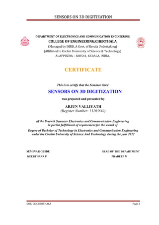
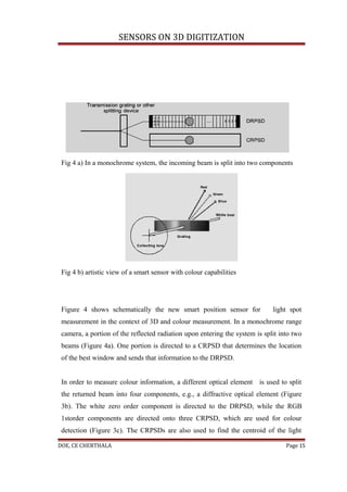
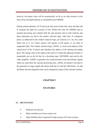
An object is illuminated by a collimated RGB laser spot and a portion of the reflected
radiation upon entering the system is split into four components by a diffracting
optical element as shown in figure 4b. The white zero order component is directed to
the DRPSD, while the RGB 1storder components are directed onto three CRPSD,
which are used for colour detection. The CRPSDs are also used to find the centroid of
the light distribution impinging on them and to estimate the total light intensity The
centroid is computed on chip with the well-known current ratio method i.e. (I1-I2)/
(I1+I2) where I1 and I2 are the currents generated by that type of sensor. [3] The
weighed centroid value is fed to a control unit that will select a sub-set (window) of
contiguous photo-detectors on the DRPSD. That sub-set is located around the
estimate of the centroid supplied by the CRPSD. Then, the best algorithms for peak
extraction can be applied to the portion of interest.
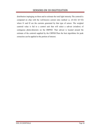
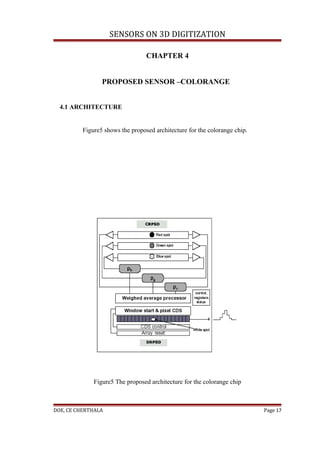
4.2 32 PIXEL PROTOTYPE CHIP
Figure6 shows the architecture and preliminary experimental results of a first
prototype chip of a DRPSD with selectable readout window. This is the first block of
a more complex chip that will include all the components.
DOE, CE CHERTHALA Page 18](https://image.slidesharecdn.com/sensorson3ddigitizationseminarreport-120902025355-phpapp02/85/Sensors-on-3-d-digitization-seminar-report-18-320.jpg)
![SENSORS ON 3D DIGITIZATION
stage and will soon be available in standard fabrication technologies. The work on the
Colorange is being finalized and work has started on a new improved architecture.
REFERENCES
[1] L.GONZO, A.SIMONI, A.GOTTARDI, DAVID STAPPA, J.A
BERNALDIN,”Sensors optimized for 3D digitization”, IEEE transactions on
instrumentation and measurement, vol 52, no.3, June 2003, pp.903-908.
[2] P.SCHAFER, R.D.WILLIAMS. G.K DAVIS, ROBERT A. ROSS,”
Accuracy of position detection using a position sensitive detector, “IEEE
DOE, CE CHERTHALA Page 23](https://image.slidesharecdn.com/sensorson3ddigitizationseminarreport-120902025355-phpapp02/85/Sensors-on-3-d-digitization-seminar-report-23-320.jpg)
![SENSORS ON 3D DIGITIZATION
transactions on instrumentation and measurement, vol 47, no.4, August 1998,
pp.914-918
[3] J.A.BERALDIN,”Design of Bessel type pre-amplifiers for lateral effect
photodiodes”, International Journal Electronics, vol 67, pp 591-615, 1989.
[4] A.M.DHAKE,”Television and video engineering”, Tata Mc Graw Hill
[5] X.ARREGUIT, F.A.VAN SCHAIK, F.V.BAUDUIN, M.BIDIVILLE,
E.RAEBER,”A CMOS motion detector system for pointing devices”, IEEE
journal solid state circuits, vol 31, pp.1916-1921, Dec 1996
[6] P.AUBERT, H.J.OGUEY, R.VUILLEUNEIR, “Monolithic optical position
encoder with on-chipphotodiodes,”IEEE J.solid state circuits, vol 23, pp.465-
473, April 1988
[7] K.THYAGARAJAN, A.K.GHATAK,”Lasers-Theory and applications”,
Plenum Press
[8] N.H.E.Weste, Kamran Eshraghian,”Principles of CMOS VLSIdesign, A
systems perspective”, Low Price Edition.
DOE, CE CHERTHALA Page 24](https://image.slidesharecdn.com/sensorson3ddigitizationseminarreport-120902025355-phpapp02/85/Sensors-on-3-d-digitization-seminar-report-24-320.jpg)

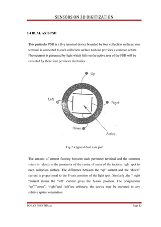
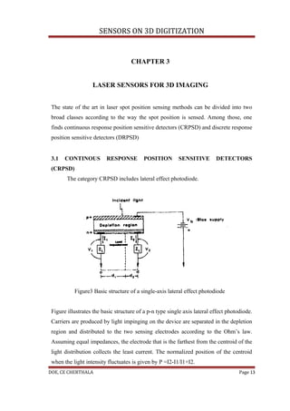
The document discusses sensors for 3D digitization. It describes two main strategies for 3D vision - passive vision which analyzes ambient light, and active vision which structures light using techniques like laser range cameras. It then discusses an auto-synchronized scanner that can provide registered 3D surface maps and color data by scanning a laser spot across a scene and detecting the reflected light with a linear sensor, producing registered images with spatial and color information.