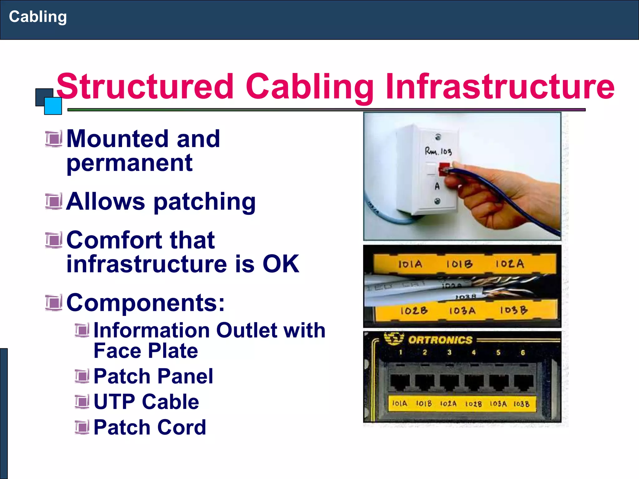
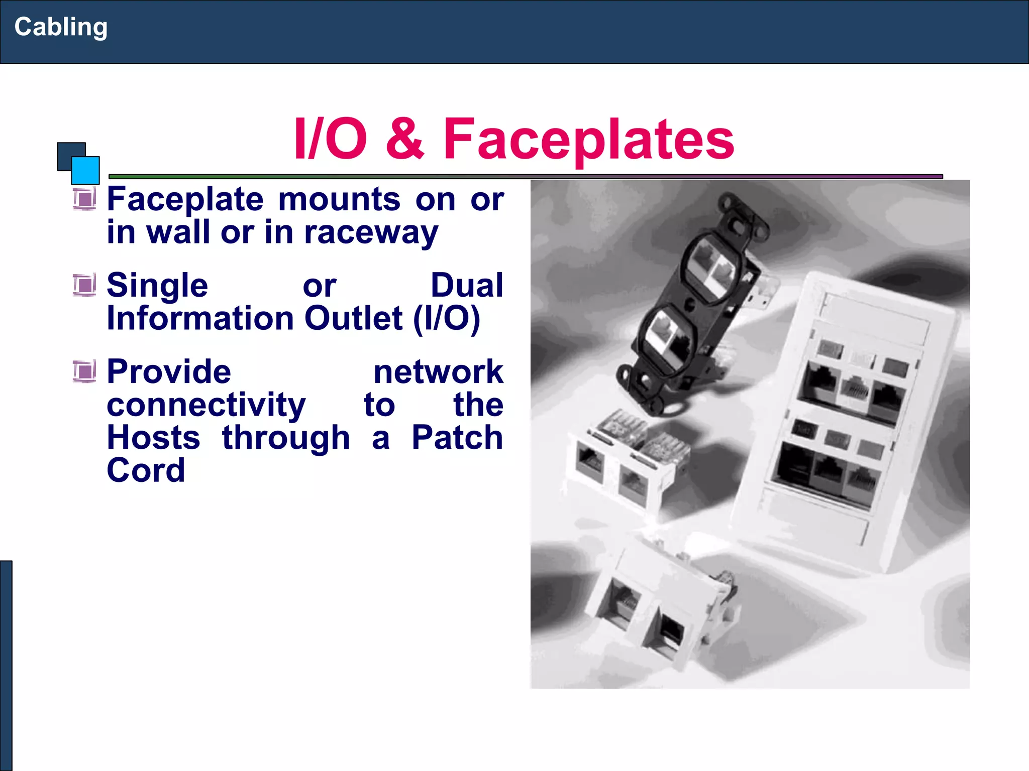
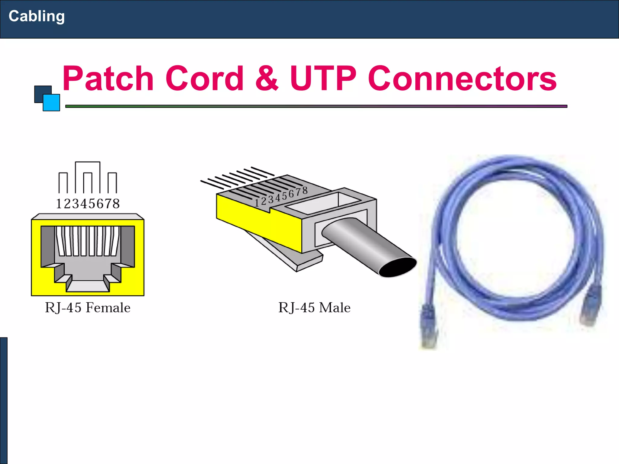
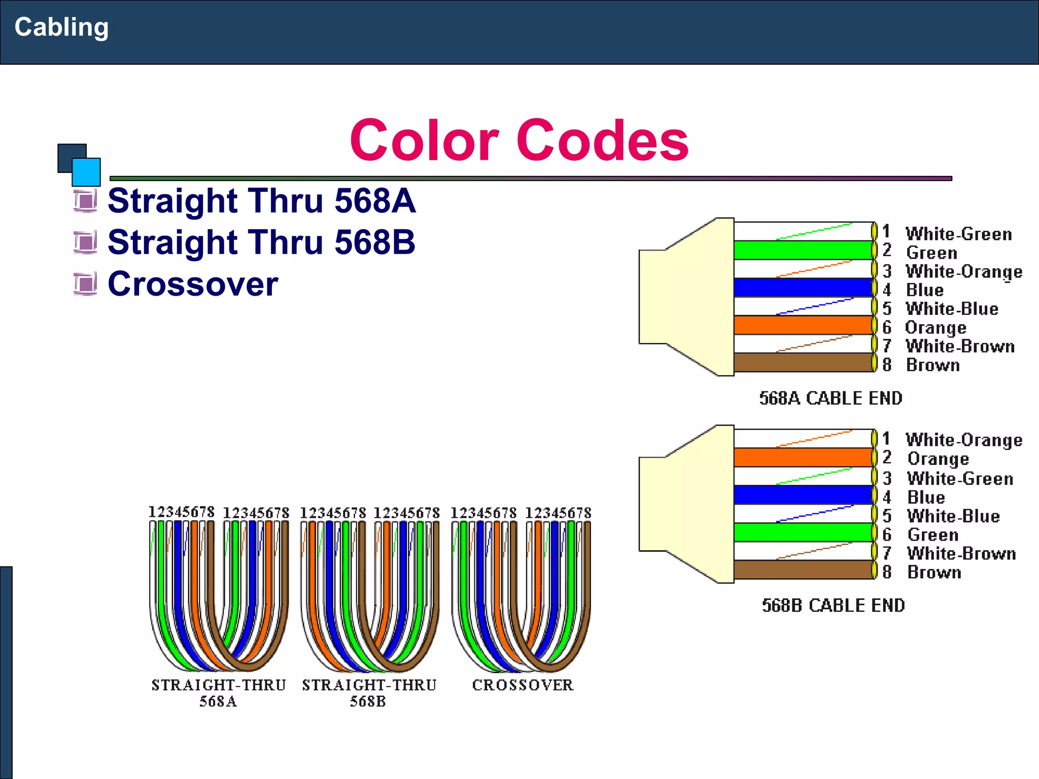
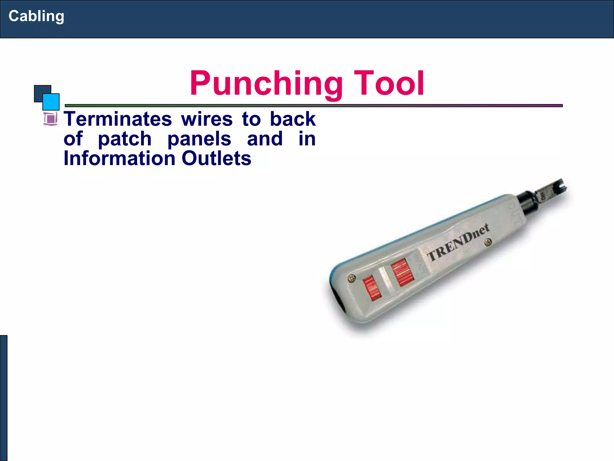
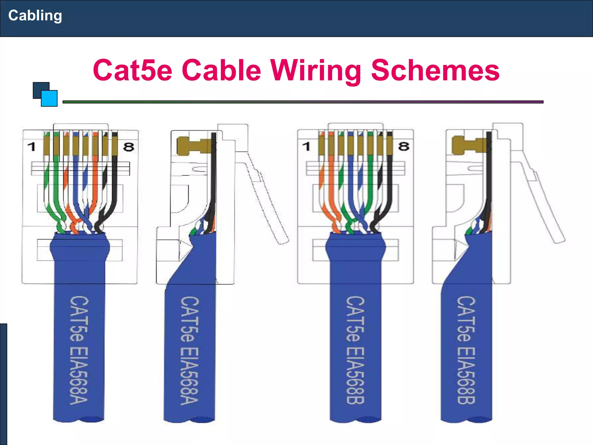
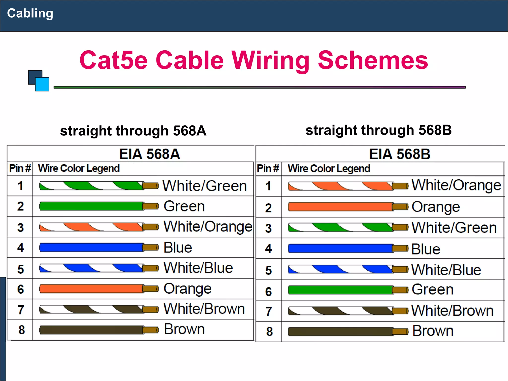
Cabling
UTP AND FIBER CABLING
Structured Cabling Infrastructure
Mounted and
permanent
Allows patching
Comfort that
infrastructure is OK
Components:
Information Outlet with
Face Plate
Patch Panel
UTP Cable
Patch Cord
Cabling
I/O & Faceplates
Faceplate mounts on or
in wall or in raceway
Single or Dual
Information Outlet (I/O)
Provide network
connectivity to the
Hosts through a Patch
Cord
Cabling
Patch Panel
Termination
punchdown in back
Patch cord plugin in
front
Cabling
Patch Cord & UTP Connectors
Cabling
Color Codes
Straight Thru 568A
Straight Thru 568B
Crossover
Cabling
Cutting, Striping & Crimping Tools
Make your own patch cords
Cuts and strips pairs
RJ45 end crimped onto ends
of wire
Cabling
Punching Tool
Terminates wires to back
of patch panels and in
Information Outlets
Cabling
Making Cables
Cabling
Wire Testing Equipment
Test wire for correct
termination of 8 wires
Cabling
Cabling Rules
Try to avoid running cables parallel to power cables.
Do not bend cables to less than four times the diameter
of the cable.
If you bundle a group of cables together with cable ties
(zip ties), do not over-cinch them. You should be able to
turn the tie with fingers.
Keep cables away from devices which can introduce
noise into them. Here's a short list: copy machines,
electric heaters, speakers, printers, TV sets, fluorescent
lights, copiers, welding machines, microwave ovens,
telephones, fans, elevators, motors, electric ovens,
dryers, washing machines, and shop equipment.
Avoid stretching UTP cables (tension when pulling
cables should not exceed 25 LBS).
Do not run UTP cable outside of a building. It presents a
very dangerous lightning hazard!
Do not use a stapler to secure UTP cables.
Cabling
Cat5e Cable Wiring Schemes
The two color code schemes used to correctly wire
the RJ-45 eight-position modular plugs are 568A and
568B. These two color codes
Cables are generally made up of 8 wires twisted
together in 4 pairs. Each pair is easily identified by one
of four primary colors and is intended to carry a signal
and its return. There are three popular wiring patterns for
Cat5e and RJ-45 cables: 568A, 568B, and a crossover
cable with 568A on one end and 568B on the opposite
end. Functionally there is no difference between a
straight through 568A to 568A cable and a straight
through 568B to 568B cable.
Cabling
Cat5e Cable Wiring Schemes
Cabling
Cat5e Cable Wiring Schemes
This illustration shows the differences between the
568A and 568B color schemes: The orange and green
pairs are interchanged as shown here. These standards
specify a maximum segment length of 100 meters (328
feet) between two devices. This length includes patch
panels and cables. When longer distances are desired,
the use of switches, repeaters, or fi ber optic media may
be required.
Cabling
Cat5e Cable Wiring Schemes
Cabling
straight through 568A straight through 568B
Step-by-Step Crimping Instructions
1. Strip a portion of the insulation, at least 3/4”, exposing
the 4 twisted pairs.
2. Untwist the wires and fan them out individually. Arrange
the wires into the correct color scheme.
Note that each of the wires is either a solid color, or a
white wire with a colored stripe. The colors are green, orange,
blue, and brown.
3. Flatten the wires in their correct order, and trim them
evenly across the top. Most crimp tools have a wire
trimmer built-in. It is best to trim the wires to about 1/2”
in length.
Cabling
Step-by-Step Crimping Instructions
4. While holding the wires flat between your thumb and
forefinger, insert the wires into the RJ45 connector, so
each wire is in its own slot. Push the wire into the RJ45,
so all 8 conductors touch the end of the connector. The
insulation jacket should extend beyond the crimp point
of the RJ45
5. Insert the RJ45 into the crimp tool receptacle and
squeeze the tool firmly
Note that a ratchet type tool should tighten down until it
no longer clicks.
6. The RJ45 should be firmly crimped to the CAT-5
insulation. It is necessary that the color scheme be
repeated identically on each end of the wire.
Cabling

3. UTP AND FIBER CABLING.pptx

  • 1.
  • 2.
    Structured Cabling Infrastructure Mountedand permanent Allows patching Comfort that infrastructure is OK Components: Information Outlet with Face Plate Patch Panel UTP Cable Patch Cord Cabling
  • 3.
    I/O & Faceplates Faceplatemounts on or in wall or in raceway Single or Dual Information Outlet (I/O) Provide network connectivity to the Hosts through a Patch Cord Cabling
  • 4.
    Patch Panel Termination punchdown inback Patch cord plugin in front Cabling
  • 5.
    Patch Cord &UTP Connectors Cabling
  • 6.
    Color Codes Straight Thru568A Straight Thru 568B Crossover Cabling
  • 7.
    Cutting, Striping &Crimping Tools Make your own patch cords Cuts and strips pairs RJ45 end crimped onto ends of wire Cabling
  • 8.
    Punching Tool Terminates wiresto back of patch panels and in Information Outlets Cabling
  • 9.
  • 10.
    Wire Testing Equipment Testwire for correct termination of 8 wires Cabling
  • 11.
    Cabling Rules Try toavoid running cables parallel to power cables. Do not bend cables to less than four times the diameter of the cable. If you bundle a group of cables together with cable ties (zip ties), do not over-cinch them. You should be able to turn the tie with fingers. Keep cables away from devices which can introduce noise into them. Here's a short list: copy machines, electric heaters, speakers, printers, TV sets, fluorescent lights, copiers, welding machines, microwave ovens, telephones, fans, elevators, motors, electric ovens, dryers, washing machines, and shop equipment. Avoid stretching UTP cables (tension when pulling cables should not exceed 25 LBS). Do not run UTP cable outside of a building. It presents a very dangerous lightning hazard! Do not use a stapler to secure UTP cables. Cabling
  • 12.
    Cat5e Cable WiringSchemes The two color code schemes used to correctly wire the RJ-45 eight-position modular plugs are 568A and 568B. These two color codes Cables are generally made up of 8 wires twisted together in 4 pairs. Each pair is easily identified by one of four primary colors and is intended to carry a signal and its return. There are three popular wiring patterns for Cat5e and RJ-45 cables: 568A, 568B, and a crossover cable with 568A on one end and 568B on the opposite end. Functionally there is no difference between a straight through 568A to 568A cable and a straight through 568B to 568B cable. Cabling
  • 13.
    Cat5e Cable WiringSchemes Cabling
  • 14.
    Cat5e Cable WiringSchemes This illustration shows the differences between the 568A and 568B color schemes: The orange and green pairs are interchanged as shown here. These standards specify a maximum segment length of 100 meters (328 feet) between two devices. This length includes patch panels and cables. When longer distances are desired, the use of switches, repeaters, or fi ber optic media may be required. Cabling
  • 15.
    Cat5e Cable WiringSchemes Cabling straight through 568A straight through 568B
  • 16.
    Step-by-Step Crimping Instructions 1.Strip a portion of the insulation, at least 3/4”, exposing the 4 twisted pairs. 2. Untwist the wires and fan them out individually. Arrange the wires into the correct color scheme. Note that each of the wires is either a solid color, or a white wire with a colored stripe. The colors are green, orange, blue, and brown. 3. Flatten the wires in their correct order, and trim them evenly across the top. Most crimp tools have a wire trimmer built-in. It is best to trim the wires to about 1/2” in length. Cabling
  • 17.
    Step-by-Step Crimping Instructions 4.While holding the wires flat between your thumb and forefinger, insert the wires into the RJ45 connector, so each wire is in its own slot. Push the wire into the RJ45, so all 8 conductors touch the end of the connector. The insulation jacket should extend beyond the crimp point of the RJ45 5. Insert the RJ45 into the crimp tool receptacle and squeeze the tool firmly Note that a ratchet type tool should tighten down until it no longer clicks. 6. The RJ45 should be firmly crimped to the CAT-5 insulation. It is necessary that the color scheme be repeated identically on each end of the wire. Cabling