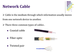
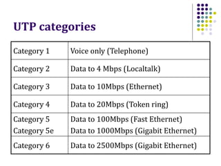
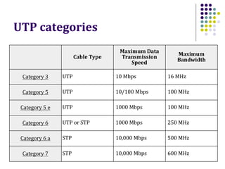
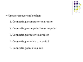
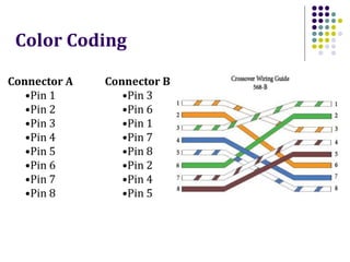
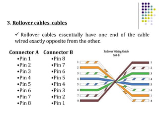
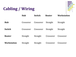
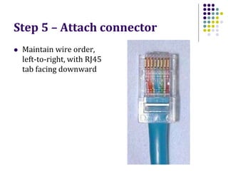
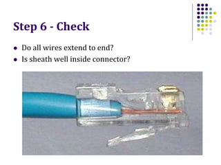
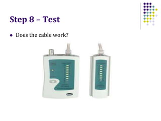
Network Cabling
 Cable is the medium through which information usually moves
from one network device to another.
Network Cable
 There three common types of cables .
 Coaxial cable
 Fiber optic
 Twisted pair
 Twisted pair cable comes in two varieties
1. Unshielded Twisted Pair (UTP) Cable
2. Shielded Twisted Pair (STP) Cable
 Unshielded twisted pair (UTP) is the most popular and is
generally the best option for LAN networks.
 The cable has four pairs of wires inside the jacket.
 RJ-45 (RJ stands for Registered Jack) is the standard
connector for unshielded twisted pair cabling.
UTP categories
Category 1 Voice only (Telephone)
Category 2 Data to 4 Mbps (Localtalk)
Category 3 Data to 10Mbps (Ethernet)
Category 4 Data to 20Mbps (Token ring)
Category 5
Category 5e
Data to 100Mbps (Fast Ethernet)
Data to 1000Mbps (Gigabit Ethernet)
Category 6 Data to 2500Mbps (Gigabit Ethernet)
Cable Type
Maximum Data
Transmission
Speed
Maximum
Bandwidth
Category 3 UTP 10 Mbps 16 MHz
Category 5 UTP 10/100 Mbps 100 MHz
Category 5 e UTP 1000 Mbps 100 MHz
Category 6 UTP or STP 1000 Mbps 250 MHz
Category 6 a STP 10,000 Mbps 500 MHz
Category 7 STP 10,000 Mbps 600 MHz
UTP categories
Cat5e cable
 1000Mbps data transmission capacity
 Runs up to 90 meters
 Terminated with RJ-45 connectors
Cabling / Wiring / Color Coding
 There are generally three main types of cabling in
computer networking.
 Out of the 8 pins that exist on both ends of an Ethernet
cable, each pin connects to the same pin on the opposite
side.
 Straight-Through wired cables are most commonly used
to connect a host to client.
1. Straight-through cables
 Use a straight-through cable when:
1. Connecting a router to a hub
2. Connecting a compute to a switch
3. Connecting a LAN port to a switch, hub, or computer
Connector A
•Pin 1
•Pin 2
•Pin 3
•Pin 4
•Pin 5
•Pin 6
•Pin 7
•Pin 8
Connector B
•Pin 1
•Pin 2
•Pin 3
•Pin 4
•Pin 5
•Pin 6
•Pin 7
•Pin 8
Color Coding
 Crossover cables are very similar to straight-through
cables, except that they have pairs of wires that crisscross.
 This allows for two devices to communicate at the same
time.
 Unlike straight-through cables, we use crossover cables
to connect like devices.
2. Crossover cables cables
 Use a crossover cable when:
1. Connecting a computer to a router
2. Connecting a computer to a computer
3. Connecting a router to a router
4. Connecting a switch to a switch
5. Connecting a hub to a hub
Connector A
•Pin 1
•Pin 2
•Pin 3
•Pin 4
•Pin 5
•Pin 6
•Pin 7
•Pin 8
Connector B
•Pin 3
•Pin 6
•Pin 1
•Pin 7
•Pin 8
•Pin 2
•Pin 4
•Pin 5
Color Coding
 Rollover cables essentially have one end of the cable
wired exactly opposite from the other.
3. Rollover cables cables
Connector A
•Pin 1
•Pin 2
•Pin 3
•Pin 4
•Pin 5
•Pin 6
•Pin 7
•Pin 8
Connector B
•Pin 8
•Pin 7
•Pin 6
•Pin 5
•Pin 4
•Pin 3
•Pin 2
•Pin 1
Hub Switch Router Workstation
Hub Crossover Crossover Straight Straight
Switch Crossover Crossover Straight Straight
Router Straight Straight Crossover Crossover
Workstation Straight Straight Crossover Crossover
Cabling / Wiring
Installing Cable Guidelines
When running cable, it is best to follow a few simple rules:
• Always use more cable than you need. Leave plenty of slack.
• Test every part of a network as you install it. Even if it is brand
new, it may have problems that will be difficult to isolate later.
• Stay at least 3 feet away from fluorescent light boxes and other
sources of electrical interference.
• If it is necessary to run cable across the floor, cover the cable
with cable protectors.
• Label both ends of each cable.
• Use cable ties (not tape) to keep cables in the same location
together.
RJ45 connector
Making connections - Tools
 Cat5e cable
 RJ45 connectors
 Cable stripper
 Scissors
 Crimping
 Tester
Making connections - Steps
1. Strip cable end
2. Untwist wire ends
3. Arrange wires
4. Trim wires to size
5. Attach connector
6. Check
7. Crimp
8. Test
Step 1 – Strip cable end
 Avoid cutting into conductor insulation
Step 2 – Untwist wire ends
 Sort wires by insulation colors
Step 3 – Arrange wires
Step 4 – Trim wires to size
 Trim all wires evenly
Step 5 – Attach connector
 Maintain wire order,
left-to-right, with RJ45
tab facing downward
Step 6 - Check
 Do all wires extend to end?
 Is sheath well inside connector?
Step 7 - Crimp
 Squeeze firmly to crimp connecter
onto cable end (8P)
Step 8 – Test
 Does the cable work?
Let’s go to work!

LO 02 Network Cabling.ppt

  • 1.
  • 2.
     Cable isthe medium through which information usually moves from one network device to another. Network Cable  There three common types of cables .  Coaxial cable  Fiber optic  Twisted pair
  • 3.
     Twisted paircable comes in two varieties 1. Unshielded Twisted Pair (UTP) Cable 2. Shielded Twisted Pair (STP) Cable  Unshielded twisted pair (UTP) is the most popular and is generally the best option for LAN networks.  The cable has four pairs of wires inside the jacket.  RJ-45 (RJ stands for Registered Jack) is the standard connector for unshielded twisted pair cabling.
  • 4.
    UTP categories Category 1Voice only (Telephone) Category 2 Data to 4 Mbps (Localtalk) Category 3 Data to 10Mbps (Ethernet) Category 4 Data to 20Mbps (Token ring) Category 5 Category 5e Data to 100Mbps (Fast Ethernet) Data to 1000Mbps (Gigabit Ethernet) Category 6 Data to 2500Mbps (Gigabit Ethernet)
  • 5.
    Cable Type Maximum Data Transmission Speed Maximum Bandwidth Category3 UTP 10 Mbps 16 MHz Category 5 UTP 10/100 Mbps 100 MHz Category 5 e UTP 1000 Mbps 100 MHz Category 6 UTP or STP 1000 Mbps 250 MHz Category 6 a STP 10,000 Mbps 500 MHz Category 7 STP 10,000 Mbps 600 MHz UTP categories
  • 6.
    Cat5e cable  1000Mbpsdata transmission capacity  Runs up to 90 meters  Terminated with RJ-45 connectors
  • 7.
    Cabling / Wiring/ Color Coding  There are generally three main types of cabling in computer networking.  Out of the 8 pins that exist on both ends of an Ethernet cable, each pin connects to the same pin on the opposite side.  Straight-Through wired cables are most commonly used to connect a host to client. 1. Straight-through cables
  • 8.
     Use astraight-through cable when: 1. Connecting a router to a hub 2. Connecting a compute to a switch 3. Connecting a LAN port to a switch, hub, or computer
  • 9.
    Connector A •Pin 1 •Pin2 •Pin 3 •Pin 4 •Pin 5 •Pin 6 •Pin 7 •Pin 8 Connector B •Pin 1 •Pin 2 •Pin 3 •Pin 4 •Pin 5 •Pin 6 •Pin 7 •Pin 8 Color Coding
  • 10.
     Crossover cablesare very similar to straight-through cables, except that they have pairs of wires that crisscross.  This allows for two devices to communicate at the same time.  Unlike straight-through cables, we use crossover cables to connect like devices. 2. Crossover cables cables
  • 11.
     Use acrossover cable when: 1. Connecting a computer to a router 2. Connecting a computer to a computer 3. Connecting a router to a router 4. Connecting a switch to a switch 5. Connecting a hub to a hub
  • 12.
    Connector A •Pin 1 •Pin2 •Pin 3 •Pin 4 •Pin 5 •Pin 6 •Pin 7 •Pin 8 Connector B •Pin 3 •Pin 6 •Pin 1 •Pin 7 •Pin 8 •Pin 2 •Pin 4 •Pin 5 Color Coding
  • 13.
     Rollover cablesessentially have one end of the cable wired exactly opposite from the other. 3. Rollover cables cables Connector A •Pin 1 •Pin 2 •Pin 3 •Pin 4 •Pin 5 •Pin 6 •Pin 7 •Pin 8 Connector B •Pin 8 •Pin 7 •Pin 6 •Pin 5 •Pin 4 •Pin 3 •Pin 2 •Pin 1
  • 14.
    Hub Switch RouterWorkstation Hub Crossover Crossover Straight Straight Switch Crossover Crossover Straight Straight Router Straight Straight Crossover Crossover Workstation Straight Straight Crossover Crossover Cabling / Wiring
  • 15.
    Installing Cable Guidelines Whenrunning cable, it is best to follow a few simple rules: • Always use more cable than you need. Leave plenty of slack. • Test every part of a network as you install it. Even if it is brand new, it may have problems that will be difficult to isolate later. • Stay at least 3 feet away from fluorescent light boxes and other sources of electrical interference.
  • 16.
    • If itis necessary to run cable across the floor, cover the cable with cable protectors. • Label both ends of each cable. • Use cable ties (not tape) to keep cables in the same location together.
  • 17.
  • 18.
    Making connections -Tools  Cat5e cable  RJ45 connectors  Cable stripper  Scissors  Crimping  Tester
  • 19.
    Making connections -Steps 1. Strip cable end 2. Untwist wire ends 3. Arrange wires 4. Trim wires to size 5. Attach connector 6. Check 7. Crimp 8. Test
  • 20.
    Step 1 –Strip cable end  Avoid cutting into conductor insulation
  • 21.
    Step 2 –Untwist wire ends  Sort wires by insulation colors
  • 22.
    Step 3 –Arrange wires
  • 23.
    Step 4 –Trim wires to size  Trim all wires evenly
  • 24.
    Step 5 –Attach connector  Maintain wire order, left-to-right, with RJ45 tab facing downward
  • 25.
    Step 6 -Check  Do all wires extend to end?  Is sheath well inside connector?
  • 26.
    Step 7 -Crimp  Squeeze firmly to crimp connecter onto cable end (8P)
  • 27.
    Step 8 –Test  Does the cable work?
  • 28.