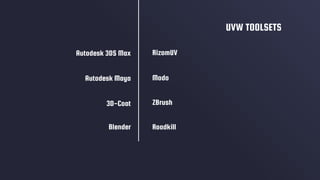
2672QCA 3D MODELLING
FOR VISUALISATION
FLATTENING 3D SHAPES
Introduction to the management of UVW
coordinates and mapping materials onto geometry.
PROJECTION MAPPING
UVW UNWRAPPING
Deriving net shapes by flattening
3D surfaces into 2D templates.
WHAT ARE UVWs?
Terminology specific to texel and
pixel mapping through coordinates.
Using map projectors to define
UVW coordinates
LECTURE CONTENTS
USEFUL TOOLS
Appropriate software for an
effective UVW pipeline.
01
02
03
04
WHAT ARE UVWs?
01
Terminology specific to texel and
pixel mapping through coordinates.
INTRODUCTION TO
UVW
Each 3D model is made out of vertices.
Each vertex usually defines the location of a point in space, a normal (used in
lighting calculations) and 1 or more texture coordinates.
These are generally designated as u for the horizontal part of the texture and v for
the vertical.
INTRODUCTION TO
UVW
When an object is textured, these coordinates are used to look up which texel or
pixel to plot from the texture.
It is easiest to think of them as percentages or ratios between:
• the left edge of texture (u = 0) and the right edge of the texture (u = 1.0), and
• from the top of the texture (v = 0) and the bottom of it (v = 1.0).
They are interpolated between the vertices and looked up for each on-screen pixel
that is rendered.
INTRODUCTION TO
UVW
Effectively, the implementation of UVW is similar to XYZ.
Where X, Y, and Z refer to 3-Dimensional coordinates within the Cartesian system, U, V, and
W refer to texture coordinates.
Most material maps are a 2D plane assigned to a 3D surface. Consequently, the coordinate
system used to describe the placement and transformation of maps is different from the X, Y,
and Z axis coordinates used in 3D space.
Specifically, mapping coordinates use the letters U, V, and W; the three letters preceding X, Y,
and Z in the alphabet.
UVW COORDINATES
The U, V, and W coordinates parallel the relative directions of X, Y, and Z coordinates.
If you look at a 2D map image, U is the equivalent of X, and represents the horizontal direction
of the map.
V is the equivalent of Y, and represents the vertical direction of the map. W is the equivalent of
Z and represents a direction perpendicular to the UV plane of the map.
UVW COORDINATES
This group of modifiers provides various tools for texture mapping: that is, managing UVW
coordinates and mapping materials onto geometry.
Unwrap UVW
UVW Map
UVW Mapping Add
UVW Mapping Clear
UVW Mapping Paste
UVW XForm
UVW MAPPING MODIFIERS
PROJECTION MAPPING
Using map projectors to define
UVW coordinates
02
By applying mapping coordinates to an object, the UVW Map modifier controls how mapped
and procedural materials appear on the surface of an object.
Mapping coordinates specify how bitmaps are projected onto an object.
The UVW coordinate system is similar to the XYZ coordinate system. The U and V axes of a
bitmap correspond to the X and Y axes.
UVW MAP MODIFIER
By default, primitive objects such as spheres and boxes have mapping coordinates, as do loft
objects and NURBS surfaces.
Scanned, imported, or hand-constructed polygonal or patch models do not have mapping
coordinates until a UVW Map modifier is applied.
This is important in your texturing process, as most of your models will be customised during
construction, therefore requiring UVW Map information.
UVW MAP MODIFIER
Apply one of the seven types of mapping coordinates to an object on a specified map channel.
A diffuse map on map channel 1 and a bump map on map channel 2 can have different
mapping coordinates and can be controlled separately by using two UVW Map modifiers in the
modifier stack
Apply one of the seven types of mapping coordinates to an object.
Transform the mapping gizmo to adjust map placement. Objects with built-in mapping
coordinates lack a gizmo.
Apply mapping coordinates to an object with no mapping coordinates, an imported mesh, for
example.
Apply mapping at the sub-object level.
USE THE UVW MAP MODIFIER TO:
For planar, spherical, cylindrical and shrink wrap maps, a short yellow line indicates the top of
the map.
The green edge of the gizmo indicates the right side of the map. On a spherical or cylindrical
map the green edge is the seam where the left and right edge meet. Gizmo must be selected in
the modifier display hierarchy to display the gizmo.
GIZMO DISPLAY FOR MAPPING TYPES
Projects the map from a single plane flat against the object, somewhat like projecting a slide.
Planar projection is useful when only one side of an object needs to be mapped. It is also
useful for obliquely mapping multiple sides, and for mapping two sides of a symmetrical
object.
PLANAR MAPPING
Projects the map from a cylinder, wrapping it around an object. Seams where the edges of the
bitmap meet are visible unless a seamless map is used. Cylindrical projection is useful for
objects that are roughly cylindrical in shape.
CYLINDRICAL MAPPING
Surrounds the object by projecting the map from a sphere. You see a seam and mapping
singularities at the top and bottom of the sphere where the bitmap edges meet at the sphere's
poles. Spherical mapping is useful for objects that are roughly spherical in shape.
SPHERICAL MAPPING
Uses spherical mapping, but truncates the corners of the map and joins them all at a single
pole, creating only one singularity. Shrink-wrap mapping is useful when you want to hide the
mapping singularity.
SHRINK WRAP MAPPING
Projects the map from the six sides of a box. Each side projects as a planar map, and the effect
on the surface depends on the surface normal. Each face is mapped from the closest box
surface whose normal most closely parallels its own normal.
BOX MAPPING
Applies a copy of the map to every face of an object. Pairs of faces sharing a hidden edge are
mapped with the full rectangular map. Single faces with no hidden edge are mapped with a
triangular portion of the map.
FACE MAPPING
UVW UNWRAPPING
03
Deriving net shapes by flattening
3D surfaces into 2D templates.
The Unwrap UVW modifier lets you assign mapping (texture) coordinates to objects and sub-
object selections, and to edit those coordinates by hand as well as with a variety of tools. You
can also use it to unwrap and edit existing UVW coordinates on an object.
You can adjust mapping to fit on Mesh, Patch, Polygon, HSDS, and NURBS models using any
combination of manual and several different procedural methods.
You can use Unwrap UVW as a self-contained UVW mapping tool and texture-coordinate
editor, or in conjunction with the UVW Map modifier.
In the latter case, you usually do so in order to use a mapping method unavailable in Unwrap
UVW, such as Shrink Wrap.
UNWRAP UVW MODIFIER
In using Unwrap UVW, you usually break up the object's texture coordinates into smaller
groups known as clusters.
That way you can position the clusters precisely over different areas of the underlying texture
map for optimal mapping accuracy.
Each of these clusters has an outline called a map seam which appears superimposed over the
object in the viewports.
UNWRAP UVW MODIFIER
UNWRAP UVW MODIFIER
USEFUL TOOLS
Appropriate software for an
effective UVW pipeline.
04
As with all areas of 3D Design, there are better tools for some tasks than others. This is true for
UVW Mapping, especially considering the tools currently on the market.
Autodesk 3DS Max and Maya can both handle UVW Mapping processes, however they are not
industry leaders for this specific task.
Other, highly specific, software is available to complete UVW Mapping in a faster, more
accurate way. As you begin to complete this process multiple times, you will desire speed and
accuracy, even if it means shifting to other software.
USEFUL TOOLS
UVW TOOLSThe following list contains toolsets that are built specifically for UVW
editing in the asset production pipeline.
RizomUV
Modo
ZBrush
UVW TOOLSETS
Roadkill
Autodesk 3DS Max
Autodesk Maya
3D-Coat
Blender
THANKS!
Does anyone have any questions?

Week 5 - Flattening 3D Shapes

  • 1.
  • 2.
    FLATTENING 3D SHAPES Introductionto the management of UVW coordinates and mapping materials onto geometry.
  • 3.
    PROJECTION MAPPING UVW UNWRAPPING Derivingnet shapes by flattening 3D surfaces into 2D templates. WHAT ARE UVWs? Terminology specific to texel and pixel mapping through coordinates. Using map projectors to define UVW coordinates LECTURE CONTENTS USEFUL TOOLS Appropriate software for an effective UVW pipeline. 01 02 03 04
  • 4.
    WHAT ARE UVWs? 01 Terminologyspecific to texel and pixel mapping through coordinates.
  • 5.
    INTRODUCTION TO UVW Each 3Dmodel is made out of vertices. Each vertex usually defines the location of a point in space, a normal (used in lighting calculations) and 1 or more texture coordinates. These are generally designated as u for the horizontal part of the texture and v for the vertical.
  • 6.
    INTRODUCTION TO UVW When anobject is textured, these coordinates are used to look up which texel or pixel to plot from the texture. It is easiest to think of them as percentages or ratios between: • the left edge of texture (u = 0) and the right edge of the texture (u = 1.0), and • from the top of the texture (v = 0) and the bottom of it (v = 1.0). They are interpolated between the vertices and looked up for each on-screen pixel that is rendered.
  • 7.
    INTRODUCTION TO UVW Effectively, theimplementation of UVW is similar to XYZ. Where X, Y, and Z refer to 3-Dimensional coordinates within the Cartesian system, U, V, and W refer to texture coordinates.
  • 9.
    Most material mapsare a 2D plane assigned to a 3D surface. Consequently, the coordinate system used to describe the placement and transformation of maps is different from the X, Y, and Z axis coordinates used in 3D space. Specifically, mapping coordinates use the letters U, V, and W; the three letters preceding X, Y, and Z in the alphabet. UVW COORDINATES
  • 10.
    The U, V,and W coordinates parallel the relative directions of X, Y, and Z coordinates. If you look at a 2D map image, U is the equivalent of X, and represents the horizontal direction of the map. V is the equivalent of Y, and represents the vertical direction of the map. W is the equivalent of Z and represents a direction perpendicular to the UV plane of the map. UVW COORDINATES
  • 11.
    This group ofmodifiers provides various tools for texture mapping: that is, managing UVW coordinates and mapping materials onto geometry. Unwrap UVW UVW Map UVW Mapping Add UVW Mapping Clear UVW Mapping Paste UVW XForm UVW MAPPING MODIFIERS
  • 12.
    PROJECTION MAPPING Using mapprojectors to define UVW coordinates 02
  • 13.
    By applying mappingcoordinates to an object, the UVW Map modifier controls how mapped and procedural materials appear on the surface of an object. Mapping coordinates specify how bitmaps are projected onto an object. The UVW coordinate system is similar to the XYZ coordinate system. The U and V axes of a bitmap correspond to the X and Y axes. UVW MAP MODIFIER
  • 14.
    By default, primitiveobjects such as spheres and boxes have mapping coordinates, as do loft objects and NURBS surfaces. Scanned, imported, or hand-constructed polygonal or patch models do not have mapping coordinates until a UVW Map modifier is applied. This is important in your texturing process, as most of your models will be customised during construction, therefore requiring UVW Map information. UVW MAP MODIFIER
  • 15.
    Apply one ofthe seven types of mapping coordinates to an object on a specified map channel. A diffuse map on map channel 1 and a bump map on map channel 2 can have different mapping coordinates and can be controlled separately by using two UVW Map modifiers in the modifier stack Apply one of the seven types of mapping coordinates to an object. Transform the mapping gizmo to adjust map placement. Objects with built-in mapping coordinates lack a gizmo. Apply mapping coordinates to an object with no mapping coordinates, an imported mesh, for example. Apply mapping at the sub-object level. USE THE UVW MAP MODIFIER TO:
  • 16.
    USE THE UVWMAP MODIFIER TO:
  • 17.
    For planar, spherical,cylindrical and shrink wrap maps, a short yellow line indicates the top of the map. The green edge of the gizmo indicates the right side of the map. On a spherical or cylindrical map the green edge is the seam where the left and right edge meet. Gizmo must be selected in the modifier display hierarchy to display the gizmo. GIZMO DISPLAY FOR MAPPING TYPES
  • 18.
    Projects the mapfrom a single plane flat against the object, somewhat like projecting a slide. Planar projection is useful when only one side of an object needs to be mapped. It is also useful for obliquely mapping multiple sides, and for mapping two sides of a symmetrical object. PLANAR MAPPING
  • 19.
    Projects the mapfrom a cylinder, wrapping it around an object. Seams where the edges of the bitmap meet are visible unless a seamless map is used. Cylindrical projection is useful for objects that are roughly cylindrical in shape. CYLINDRICAL MAPPING
  • 20.
    Surrounds the objectby projecting the map from a sphere. You see a seam and mapping singularities at the top and bottom of the sphere where the bitmap edges meet at the sphere's poles. Spherical mapping is useful for objects that are roughly spherical in shape. SPHERICAL MAPPING
  • 21.
    Uses spherical mapping,but truncates the corners of the map and joins them all at a single pole, creating only one singularity. Shrink-wrap mapping is useful when you want to hide the mapping singularity. SHRINK WRAP MAPPING
  • 22.
    Projects the mapfrom the six sides of a box. Each side projects as a planar map, and the effect on the surface depends on the surface normal. Each face is mapped from the closest box surface whose normal most closely parallels its own normal. BOX MAPPING
  • 23.
    Applies a copyof the map to every face of an object. Pairs of faces sharing a hidden edge are mapped with the full rectangular map. Single faces with no hidden edge are mapped with a triangular portion of the map. FACE MAPPING
  • 24.
    UVW UNWRAPPING 03 Deriving netshapes by flattening 3D surfaces into 2D templates.
  • 25.
    The Unwrap UVWmodifier lets you assign mapping (texture) coordinates to objects and sub- object selections, and to edit those coordinates by hand as well as with a variety of tools. You can also use it to unwrap and edit existing UVW coordinates on an object. You can adjust mapping to fit on Mesh, Patch, Polygon, HSDS, and NURBS models using any combination of manual and several different procedural methods. You can use Unwrap UVW as a self-contained UVW mapping tool and texture-coordinate editor, or in conjunction with the UVW Map modifier. In the latter case, you usually do so in order to use a mapping method unavailable in Unwrap UVW, such as Shrink Wrap. UNWRAP UVW MODIFIER
  • 26.
    In using UnwrapUVW, you usually break up the object's texture coordinates into smaller groups known as clusters. That way you can position the clusters precisely over different areas of the underlying texture map for optimal mapping accuracy. Each of these clusters has an outline called a map seam which appears superimposed over the object in the viewports. UNWRAP UVW MODIFIER
  • 27.
  • 28.
    USEFUL TOOLS Appropriate softwarefor an effective UVW pipeline. 04
  • 29.
    As with allareas of 3D Design, there are better tools for some tasks than others. This is true for UVW Mapping, especially considering the tools currently on the market. Autodesk 3DS Max and Maya can both handle UVW Mapping processes, however they are not industry leaders for this specific task. Other, highly specific, software is available to complete UVW Mapping in a faster, more accurate way. As you begin to complete this process multiple times, you will desire speed and accuracy, even if it means shifting to other software. USEFUL TOOLS
  • 30.
    UVW TOOLSThe followinglist contains toolsets that are built specifically for UVW editing in the asset production pipeline.
  • 31.
  • 32.