Download to read offline
![FOM-E1/T1
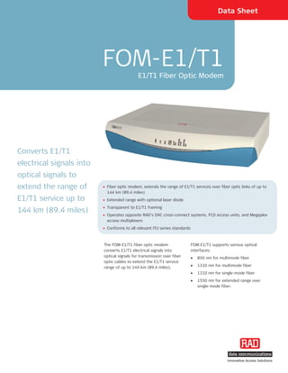
E1/T1 Fiber Optic Modem
FOM-E1/T1 operation complies with ITU Front panel LEDs indicate system faults in
G.703 and G.955 standards. the electrical and fiber optic circuits.
An alarm relay port transmits the following The modem supports activation of local
alarm conditions: and remote loopbacks.
• Major alarm – Low level of E1/T1 FOM-E1/T1 is also available as a plug-in
electrical input or high bit error rate at card for RAD’s 19-inch modem rack,
the fiber optic interface ASM-MN-214.
• Minor alarm – AIS received at electrical
or fiber optic interface.
Figure 1. Point-to-Point Application
Table 1. FOM-E1/T1 Fiber Optic Interface Characteristics
Option Wavelength Fiber Type Transmitter Type Typical Power Receiver Connector Typical Max.
Sensitivity Range
[nm] [μm] [dBm] [dBm] [km] [mi]
85 850 62.5/125 multimode VCSEL/LED -18 (FOM-E1/T1/R) -35 (FOM-E1/T1/R) ST, SC, FC 4.8 3.0
VCSEL -7 (FOM-E1/T1) -34 (FOM-E1/T1) 6.7 4.2
13MM 1310* 62.5/125 multimode LED -18 -31 ST, SC 9.3 5.7
13L 1310 9/125 single mode Laser -12 -40 ST, SC, FC 50.0 31.0
13LH 1310* 9/125 single mode Laser (long haul) -2 -40 ST, SC, FC 70.0 43.4
15L 1550 9/125 single mode Laser -12 -38 ST, SC, FC 92.0 57.0
15LH 1550* 9/125 single mode Laser (long haul) -1 -40 ST, SC, FC 144.0 89.4
SF1 1310/1550* 9/125 single mode Laser (WDM), SF1 -12 -34 SC 38.0 23.6
SF2 1550/1310* 9/125 single mode Laser (WDM), SF2 -12 -34 SC 38.0 23.6
SF3 1310* 9/125 single mode Laser (single fiber), SF3 -12 -27 SC/APC 20.0 12.4
* Available in standalone version only.](https://image.slidesharecdn.com/fom-e1t12-0ds-120125091633-phpapp01/85/Fom-e1-t1-2-0-ds-2-320.jpg)
![Data Sheet
Specifications GENERAL Power (standalone only)
Wide range: 100–240 VAC or
Diagnostics
E1/T1 ELECTRICAL INTERFACE –40 to –60 VDC
Local and remote loopbacks activated via
Transmission Rate back panel DIP switch DC only: 24 VDC
E1: 2.048 Mbps Power Consumption
Alarm Relay Port
T1: 1.544 Mbps Dry contact via 9-pin, D-type, female AC: 8 VA max
connector DC: 4W max
Zero Suppression
E1: HDB3 Indicators Physical
T1: B8ZS, AMI PWR (green) – power status Height: 4.37 cm (1.7 in)
LLB (yellow) – local loopback status Width: 24.0 cm (9.4 in)
Impedance
E1: 75Ω, unbalanced or RLB (yellow) – remote loopback status Depth: 17.0 cm (6.7 in)
120Ω, balanced OPTICAL AIS (yellow) –"all 1s" string Weight: 0.5 kg (1.1 lb)
T1: 100Ω, balanced received at the fiber optic interface
Environment
Connectors OPTICAL LOSS (red) – BER is over 10–6 Temperature: 0°–50°C (32°–122°F)
RJ-45, balanced ELEC LOSS (red) – electrical interface input Humidity: Up to 90%, non–condensing
BNC, unbalanced is below G.703 level
ELEC LOSS (red) – electrical interface input
FIBER OPTIC INTERFACE is below G.703 level
See Table 1 ELEC AIS (yellow) – "all 1s" string received
at the electrical interface
Table 2. Fiber Optic Modem Comparison Chart
Feature FOM-E1/T1 FOMi-E1/T1 FOM-20 FOM-40 FOMi-40 FOM-E3/T3 FOMi-E3/T3 FOM-E3/T3 ETH
Max. Data Rate E1/T1 E1/T1 19.2–256 56–2048 56–2048 E3/T3 E3/T3 E3/T3
[kbps]
Interfaces G.703 G.703 Serial, Serial, Ethernet Serial, G.703 G.703, HSSI 10/100BaseT
Ethernet Ethernet, VLAN Bridge
E1/T1
Laser Diode
Option
SNMP
Management
Card Version ASM-MN-214 LRS ASM-MN-214 ASM-MN-214 LRS LRS
for Rack](https://image.slidesharecdn.com/fom-e1t12-0ds-120125091633-phpapp01/85/Fom-e1-t1-2-0-ds-3-320.jpg)


The FOM-E1/T1 fiber optic modem: - Converts E1/T1 electrical signals to optical signals to extend the service range up to 144 km over fiber optic cables. - Supports various optical interfaces including 850nm and 1310nm for multimode fiber, and 1310nm and 1550nm for single-mode fiber. - Complies with relevant ITU standards and provides LED indicators and an alarm relay port for fault conditions.


