This document presents a 24VDC input dimmable electronic ballast circuit for fluorescent lighting. It compares boost and push-pull DC-DC converter topologies for powering the ballast from a DC source like solar panels. A new closed-loop dimming control method is introduced to regulate lamp current over a 100% to 10% dimming range. Experimental results show the push-pull ballast design operates well over the input voltage range and provides linear dimming control.
International Journal of Engineering Research and Development (IJERD)IJERD Editor
journal publishing, how to publish research paper, Call For research paper, international journal, publishing a paper, IJERD, journal of science and technology, how to get a research paper published, publishing a paper, publishing of journal, publishing of research paper, reserach and review articles, IJERD Journal, How to publish your research paper, publish research paper, open access engineering journal, Engineering journal, Mathemetics journal, Physics journal, Chemistry journal, Computer Engineering, Computer Science journal, how to submit your paper, peer reviw journal, indexed journal, reserach and review articles, engineering journal, www.ijerd.com, research journals,
yahoo journals, bing journals, International Journal of Engineering Research and Development, google journals, hard copy of journal
Metal Halide HID lamps are becoming popular because of its high efficacy. The
operating characteristic of Metal Halide (MH) HID lamps is complex as it has several stage
of operation. The objective of this paper is to design an electric control system for metal
halide high intensity discharge (HID) lamps using half bridge inverter. The LCC resonant
mode is used to provide the sufficient voltage and current to the MH lamp during its
ignition and normal running condition. An adaptive control method is used to regulate the
lamp power. A close loop current control method is used. In this close loop Type-3 regulator
is used as a compensator. The variation in lamp power with and without loop is discussed.
The stability of the close loop is also analysed. PSIM Simulation Software is used to do this
analysis.
Torque Ripple Minimization of a BLDC Motor Drive by Using Electronic Commutat...AI Publications
Brushless DC motors are having a major problem with harmonics in torque. The variations in speed and production of noise should be minimized by using proper topologies. BLDC motors have been gaining attention from different Industrial and domestic appliance manufacturers, because of their high efficiency, high power density and easy maintenance and low cost. This paper presents a three phase BLDC motor with low cost drive to be driven without DC link capacitor. The proposed technique uses an electronic commutation and operates the machine exclusive of the intermediate DC link capacitor. The designing of Brushless DC motor drive system along with control system for torque ripple minimization, speed controller and current controllers are presented using MATLAB / SIMULINK and results are evaluated.
discusses about the reduction of commutation torque ripple in BLDC motor and various convention methods and the proposed method for 2 level inverter and 3 level inverter
Welcome to International Journal of Engineering Research and Development (IJERD)IJERD Editor
journal publishing, how to publish research paper, Call For research paper, international journal, publishing a paper, IJERD, journal of science and technology, how to get a research paper published, publishing a paper, publishing of journal, publishing of research paper, reserach and review articles, IJERD Journal, How to publish your research paper, publish research paper, open access engineering journal, Engineering journal, Mathemetics journal, Physics journal, Chemistry journal, Computer Engineering, Computer Science journal, how to submit your paper, peer reviw journal, indexed journal, reserach and review articles, engineering journal, www.ijerd.com, research journals,
yahoo journals, bing journals, International Journal of Engineering Research and Development, google journals, hard copy of journal
High Gain Interleaved Cuk Converter with Phase Shifted PWMtheijes
DC-DC converters with ripple on input source current inject harmonics to the power system which in turn cause harmful to other connected devices. These converters with high efficiency and low input current ripple are essential in most common applications. Cuk converter provide reduction in the ripple of input and output current compared to other traditional converters which can be used for either step up or step down applications. Generally, a conventional cuk converter in continuous conduction mode brings in large current ripple on input side which in turn injects harmonics to the source. This undesirable input current ripple is mitigated by employing the interleaved cuk converter (ICC). Simulation results of ICC shows that the input ripple current has been reduced significantly from 7.5A to 1A compared to conventional cuk converter. The energy-transfer-capacitor in basic cuk converters is splitted into two capacitors. The rectifier diode is replaced by two diodes that form with the two capacitors a switched-capacitor circuit, which appears connected between the input and output inductances of the original converter. A hybrid circuit, presenting a higher DC voltage ratio than the classical Cuk circuit can be obtained. A high gain interleaved cuk converter is designed and simulated in MATLAB/SIMULINK for 40V with an input of 20V.
Performance of Six-Pulse Line-Commutated Converter in DC Motor Drive ApplicationZunAib Ali
This paper presents the speed control of DC motor using six pulse controlled rectifier. The
conventional Proportional Integral (PI) control is used for firing angle control. The armature current is fed
back and compared with reference current representing desired speed values. The proposed system is
simulated using SimPowerSystem and Control System Matlab toolbox. The time domain plot of reference
and actual armature current are shown in results section. The results are satisfactory with deleterious effect
on input current. The frequency plot of input current is provided to show the harmonic contents, generated
as a result of control operation.
The document discusses DC to AC conversion using inverters. It describes the basic concept and components of inverters including single-phase, full-bridge, and three-phase inverter topologies. It also covers modulation techniques such as pulse width modulation (PWM) and discusses how they affect the output waveform harmonics.
A New Filtering Method and a Novel Converter Transformer for HVDC System.IOSR Journals
This document presents a new filtering method and converter transformer design for HVDC systems. The new design aims to address issues with traditional converter transformers and passive filtering methods, such as additional harmonic losses and difficulties meeting insulation requirements.
The new converter transformer uses a prolonged-delta winding configuration and phase shifts of 15 degrees to provide 12-phase commutation voltages. It also employs an inductive filtering mechanism where a tap connects the prolonged and common windings to an LC resonance circuit. This allows harmonic currents to balance out so no inductive harmonics flow in the primary winding.
Simulation results show the new design greatly reduces harmonic content and transformer losses compared to traditional designs. The primary current waveform has lower distortion and THD with the
To overcome the problem of mismatched voltage levels between parallel-connected low voltage photovoltaic (PV)
arrays and the higher grid voltage, a hybrid boost three level dc-dc converter is developed based on three level inverter with
the traditional single phase diode clamping. Only one inductor, two capacitors in series, and those power switches and diodes,
which are easy to be integrated, are used for establish the topology with transformerless high voltage gain. The operation
principle of the topology is analyzed, and then the pulse width modulation (PWM) control method is obtained according to
the switching functions about the output pulse voltages of both half-bridges. Therefore, the converter can not only operate
with high voltage gain, but also make the duty cycles of power switches closer to 0.5. A feedforward closed loop control
operation is proposed such that even in varying input the converter is capable of giving a constant output. Finally an
experimental is set up in the laboratory for open loop control operation. All experimental results verify the feasibility of the
circuit and validity of the PWM control method.
This document discusses different classes of power amplifiers - Class A, B, AB, C. Class A amplifiers provide output over the full cycle but have low efficiency. Class B amplifiers have higher efficiency but provide output for only half the cycle, so use two transistors in a push-pull configuration to generate a full output cycle. Push-pull amplifiers eliminate even harmonics and have other advantages over single-ended amplifiers. The maximum theoretical efficiency of Class B amplifiers is 78.5%. The document also provides equations to calculate operating points, input power, output power, and efficiency.
PWM Switched Voltage Source Inverter with Zero Neutral Point Potentialijsrd.com
A three phase three-level pulse width modulation
(PWM) switched voltage source inverter with zero neutral
point potential is designed. It consists of three single-phase
inverter modules and each module is composed of a
switched voltage source and inverter switches. The major
advantage is that the peak value of the phase output voltage
is twice as high as that of the conventional neutral-pointclamped
PWM inverter. Thus, the proposed inverter is
suitable for applications with low voltage sources such as
batteries, fuel cells, or solar cells. Furthermore, three-level
output waveforms of the inverter can be achieved without
the switch voltage unbalance problem. Since the average
neutral point potential of the inverter is zero, a common
ground between the input stage and the output stage is
possible. Therefore, it can be applied to a transformer-less
power conditioning system. The SVS inverter is tested by a
PSIM simulation and hardware is implemented and verified.
This presentation was presented to Dr. Chongru Liu in North China Electric Power University,Beijing,China by Mr. Aazim Rasool. This presentation will help to understand the control of HVDC system. Animations are not working like ppt. so I apologize on this.
The document discusses torque ripple minimization in BLDC motors. It describes how torque ripples occur during current commutation between phases in BLDC motors due to mismatched current rise and fall times. A proposed PWM switching strategy uses modified PWM signals to speed up or slow down the energized phase current during commutation based on motor speed, minimizing torque ripples. Experimental results show that the modified PWM approach reduces current spikes and dips during commutation, resulting in lower torque ripple compared to conventional PWM control.
Control of HVDC Transmission System Based on MMC with Three-Level Flying Capa...Anand Parakkat Parambil
The document contains a list of figures for chapters 3-5 of a thesis on controlling an HVDC transmission system based on modular multilevel converters (MMC) with three-level flying capacitor submodules. Chapter 3 describes the system and modeling of the MMC, including the topology and operation of the converter. Chapter 4 discusses the control and modulation of the MMC-HVDC system, including AC and DC current control loops for the two MMC stations and arm balancing control. Chapter 5 presents simulation results evaluating the system.
LCL Filter for Grid Connected VSC Converter
Comprehensive analysis and modeling of the three-phase LCL filter for VSC converters, suitable for wind energy or photovoltaic applications.
Power system analysis material -Mathankumar.s VMKVECMathankumar S
This document provides an overview of power systems, including different types of power generation sources like thermal, hydroelectric, nuclear, gas turbine, and diesel power plants. It also describes the basic components of a power system such as generators, transformers, transmission lines, and loads. Additionally, it discusses the voltage structure of electric power systems including generating stations, transmission systems, and distribution systems. Finally, it introduces the need for system analysis in planning and operating power systems, and distinguishes between steady state and transient state stability analysis.
Power Amplifiers: Classification of amplifiers, Class A power Amplifiers and their analysis, Harmonic Distortions,
Class B Push-pull amplifiers and their analysis, Complementary symmetry push pull amplifier, Class AB power
amplifier, Class-C power amplifier, Thermal stability and Heat sinks, Distortion in amplifiers.
This document provides information about different classes of amplifiers, including Class A, Class B, Class AB, and transformer-coupled amplifiers. It discusses the key characteristics of each type of amplifier, such as conduction angle, efficiency, and whether they use a single transistor or complementary pair. The Class A amplifier has a conduction angle of 360 degrees but low efficiency. Class B amplifiers have a conduction angle of 180 degrees and higher efficiency of around 70% but can experience crossover distortion without additional biasing. Class AB amplifiers add small bias voltages to eliminate crossover distortion while maintaining higher efficiency than Class A.
This document describes an AC-DC matrix converter based on a Cockcroft-Walton voltage multiplier circuit. The converter uses a four bidirectional-switch matrix converter between an AC source and a CW circuit to provide high power factor, adjustable output voltage, and low output ripple. The matrix converter operates at two frequencies - one for power factor correction control and one to set the output frequency. Simulation results show the converter improves efficiency and power factor while reducing output voltage ripple compared to a conventional CW circuit. A 10V AC to 50V DC prototype was built and tested.
This document discusses different classes of amplifiers:
1. Class A amplifiers have a transistor conducting current at all times, for a full 360 degree conduction angle. They produce minimal distortion but have low efficiency.
2. Class AB amplifiers have a small amount of bias current, conducting for more than 180 degrees but less than 360. They have some overlap between halves of a push-pull stage to reduce crossover distortion.
3. Transformer-coupled Class A amplifiers can improve efficiency by matching load and amplifier impedances using a transformer, reaching up to 40% efficiency. However, transformers add cost and size.
International Journal of Engineering Research and DevelopmentIJERD Editor
This document summarizes a study investigating two soft-switched isolated DC-DC converter topologies for auxiliary power supply in railways. The converters aim to reduce size and weight by using a lightweight medium frequency transformer instead of heavy 50Hz transformers. One proposed topology uses an auxiliary circuit on the secondary side to achieve zero-current switching for the primary inverter switches. Equations are provided to analyze the operating modes and design considerations of this topology, including resonant component sizing, power device ratings, and output voltage characteristics based on input voltage and load current. Analytical expressions are given to determine maximum stresses on the power devices under different operating conditions.
Low Power and Fast Transient High Swing CMOS Telescopic Operational AmplifierIJERA Editor
CMOS telescopic operational amplifier with high-swing and high-performance is described in this paper. The
swing is attained by using the tail and current source-transistors in deep-linear region. The resultant deprivation
in parameters like differential gain, CMRR and added characteristics are recompensed by using regulatedcascode
differential gain enhancement and a replica-tail feedback technique. Operating at power supply of 3.3V,
the power consumption, slew rate and settling time are improved using transmission controlled pass circuitry
and level amplifier. It is shown through simulations that the Op-Amp preserves its high CMRR and unity gain
frequency.
Power systems can be modeled and analyzed using per-unit representations of components. Key models include:
1) Generator models that specify real and reactive power injection or terminal voltage and current.
2) Transformer models using an equivalent circuit with magnetizing reactance and resistance.
3) Load models like constant impedance, current, or power to represent different load characteristics.
4) Transmission lines modeled as series impedances.
The per-unit system allows analysis of different voltage levels on a common scale and simplifies modeling of components.
This document contains 5 problems related to transmission lines and circuits. Problem 1 asks to calculate the ABCD parameters of a transmission line system including transformers. Problem 2 gives the ABCD parameters and asks for the sending end voltage, current, and power factor. Problem 3 asks for the sending end voltage given two lines in parallel. Problem 4 asks for the ABCD parameters and characteristic impedance of a pi network transmission line. Problem 5 asks for the resistances of an equivalent T-network model of a two-port resistive circuit.
This document discusses the development and structure of the Swedish power system. It began with hydroelectric power stations and later added coal and nuclear power plants. A 220-400kV transmission system was developed to transmit power from northern hydroelectric sources to industrial areas in the south and middle of Sweden. Today the system includes high voltage transmission lines, transformers and substations connecting large centralized power plants ranging from 1000MW to individual consumer needs of kW. The main sources of electricity in Sweden are now hydroelectric, nuclear and some combined heat and power, with hydro and nuclear providing most generation.
This document provides an overview of forward-type switched mode power supplies (SMPS). It begins by stating the objectives and introducing the basic topology, which consists of a switching device, transformer, and rectification/filtering circuit. It then explains the principles of operation, including two modes - the powering mode when the switch is on, and the freewheeling mode when it is off. Key points covered include the relationship between input/output voltages and duty cycle, and factors that influence the sizing of filter components like the switching frequency. Practical considerations like non-ideal transformer characteristics necessitate modifications to the basic circuit.
Highly efficient Active Front End enables trouble free operation of low harmo...Schneider Electric
NEW 3 level Active Front End (AFE) technology from Schneider Electric allows trouble free operation, both for mains supply side and motor side.
This technology allows exceptional low harmonics impact on the main side, which helps to protect other assets while saving energy. It also solves the major issue existing with 2 level AFE which can create premature wear on motors' bearings. By suppressing the common mode voltage, the 3 level AFE technology ensures the motor is running without potential issue, extending the motor’s lifetime and saving maintenance costs.
This document describes a solar compatible multiple output DC to DC converter designed for a personal computer system. It aims to minimize the disadvantages of conventional switched mode power supplies (SMPS) by using triple buck converters with a single DC to DC conversion from a solar panel, rather than multiple AC to DC conversions. The design uses a dual buck converter IC to produce +5V and +3.3V outputs and a single buck converter to produce a +12V output from a 48V DC input from the solar panel. This avoids unnecessary conversions and improves efficiency over conventional SMPS and UPS systems.
This document summarizes a research paper on an AC/DC converter with active power factor correction applied to a DC motor drive. The proposed circuit uses a quasi-active power factor correction technique with an auxiliary winding on a flyback converter transformer to shape the input current and improve the power factor. Simulation results are presented showing the performance of the circuit when applied to a DC motor load. The circuit aims to provide power factor correction without an active switch and control circuit to reduce costs and improve efficiency compared to traditional two-stage converter designs.
International Journal of Engineering Research and DevelopmentIJERD Editor
Electrical, Electronics and Computer Engineering,
Information Engineering and Technology,
Mechanical, Industrial and Manufacturing Engineering,
Automation and Mechatronics Engineering,
Material and Chemical Engineering,
Civil and Architecture Engineering,
Biotechnology and Bio Engineering,
Environmental Engineering,
Petroleum and Mining Engineering,
Marine and Agriculture engineering,
Aerospace Engineering.
This document presents a design and simulation of a boost converter with input ripple cancellation for applications like fuel cells. It proposes a boost converter with a tapped inductor and ripple cancellation network (RCN) consisting of a small inductor and capacitor. This helps reduce input current ripples compared to a conventional boost converter. The RCN achieves input ripple cancellation by having its inductor current increase as the main inductor current decreases and vice versa. Simulation results show the proposed converter has lower input current ripple while maintaining output voltage regulation through a closed loop controller.
This document summarizes two possible control techniques for indirectly shaping the input current of a buck power factor correction (PFC) converter by shaping the inductor current. It analyzes the harmonic content of the line current for each control technique to determine the allowable voltage gain (K value) for meeting various harmonic regulations. It then presents a sine-squared modulation control technique that shapes the average inductor current as a sine-squared waveform to indirectly shape the input current in a simplified manner without an averaging circuit. Simulation waveforms and equations are provided to analyze the line current harmonic distortion for different K values using this control technique. Experimental results from a 300W dual interleaved buck PFC converter are also mentioned.
The document proposes a new high step up interleaved DC-DC converter with a voltage multiplier module for a photovoltaic grid system. The system takes a low DC voltage input, typically from a solar panel, and boosts it to a high DC voltage using the converter. It then uses an inverter to convert the high DC voltage to AC. A filter is used to reduce distortion before connecting the output to a load. The proposed converter achieves a high step up ratio without an extreme duty cycle by integrating a conventional boost converter and voltage multiplier module. This design reduces current stress on components and improves efficiency compared to existing boost converter approaches. Simulation results show it can boost a 40V input to 331V output with up to
New Topology for Transformer less Single Stage -Single Switch AC/DC ConverterIJMER
This paper presents a transformer less single-stage single-switch ac/dc converter suitable for universal line applications (90–270 Vrms). The topology consists of a buck-type power-factor correction (PFC) cell with a buck–boost dc/dc cell and part of the input power is directly coupled to the output after the first power processing. With this direct power transfer and sharing capacitor voltages, the converter is able to achieve efficient power conversion, high power factor, low voltage stress on intermediate bus (less than 120 V) and low output voltage without a high step-down transformer. The absence of transformer reduces the size of the circuit , component counts and cost of the converter. Unlike most of the boost-type PFC cell, the main switch of the proposed converter only handles the peak inductor current of dc/dc cell rather than the superposition of both inductor currents. Tight voltage regulation is provided by using PID controller. Detailed analysis and design procedures and simulation of the proposed circuit are given .
This document summarizes a research paper on a single-phase single-stage multi-level AC-DC converter for power factor correction. It presents a five-level AC-DC converter topology that can achieve high power quality with reduced voltage stress. The converter consists of an AC input section, five-level DC-DC converter, and DC link. It operates in five modes to generate five distinct output voltage levels. Simulation results show the converter achieves power factor correction at the input and regulated output voltage. The five-level topology is an improvement over previous three-level converters as it further reduces voltage stress on the switches.
Modified Bidirectional Converter with Current Fed InverterIJPEDS-IAES
A bidirectional dc-dc converter with multiple outputs are concatenated with a
high frequency current source parallel resonant push pull inverter is
presented in this paper. The two outputs are added together and it is taken as
the input source for the inverter. The current source parallel resonant push
pull inverter implemented here with high frequency applications like
induction heating, Fluorescent lighting, Digital signal processing sonar. This
paper proposes a simple photovoltaic power system consists of a
bidirectional converter and a current fed inverter for regulating the load
variations. Solar power is used as the input source for the system. Simulation
of the proposed system is carried out in PSIM software and experimentally
verified the results.
Modeling and Analysis of Transformerless High Gain Buck-boost DC-DC ConvertersIAES-IJPEDS
This paper proposes a transfomerless switched capacitor buck boost converter model, which provides higher voltage gain and higher efficiency when compared to the conventional buck boost converter. The averaged model based on state- space description is analyzed in the paper. The simulation results are presented to confirm the capability of the converter to generate high voltage ratios. The comparison between the proposed model and the traditional model is also provided to reveal the improvement. The proposed converter is suitable for for a wide application which requires high step-up DC-DC converters such as DC micro-grids and solar electrical energy.
International Journal of Engineering Research and DevelopmentIJERD Editor
The document proposes a new multi-string inverter topology for photovoltaic systems connected to the electric grid. It connects multiple PV strings in parallel through diodes before boosting the DC voltage and converting it to AC with an inverter. Simulations show the multi-string topology offers higher efficiency compared to traditional string inverters by reducing losses.
Modern trend in power generation is the use of two-stage configuration i.e., allocating a single PV cell
to a converter to produce grid voltage of adequate requirement and then to convert DC to AC voltage for grid
cnnection. Usually, the first stage is a DC-DC boost type converter which is responsible for extracting maximum
power from panel and boosting PV voltage to a value higher than peak of grid voltage. A converter is proposed,
which is derived from an active network based converter, is chosen as the first stage and a five level inverter is
used as the second stage of the configuration. Thus, in overall, the converter used is having high gain and reduced
switching stress. The Inverter used is having the advantage of low filter requirement, reduced stress, EMI and
reduced THD level. A closed loop control of the converter is done to maintain constant output voltage under
varying input voltage. MATLAB R2014a version software is used to simulate the model. The prototype of the
two stage configuration was developed and tested in the laboratory and results were verified using PIC 16F877A.
Fuzzy Logic Controller Based High Frequency Link AC-AC Converter For Voltage ...IJTET Journal
Abstract—In this paper, an advanced high frequency link AC-AC Push-pull cycloconverter for the voltage compensation is proposed in order to maintain the power quality in electric grid. The proposed methodology can be achieve arbitrary output voltage without using large energy storage elements. So that the system is more steadfast and less costly compared with the conventional inverter topology. Additionally, the proposed converter does not contain any line frequency transformer, which reduces the cost further. The control scheme for the push pull cycloconverter employs the fuzzy logic controller based sinusoidal pulse width modulation (SPWM) to accomplish better performance on voltage compensation, like unbalanced voltage harmonics elimination. The simulation results are given to show the effectiveness of the proposed high frequency link AC-AC converter and fuzzy logic controller based SPWM technology
Electric Power Converter with a Wide Input Voltage RangeIAES-IJPEDS
The electric power converter for downhole telemetry systems of oil-well
pumps include a downhole block connected to the pump that contains
electronic circuits required for the operation of the motor pump sensors
and transmission of data about their condition to the surface are described.
A few methods of electric power conversion for this purpose are considered.
The circuit contained two steps of voltage converting are proposed.
The electrical scheme of this method is considered in the article. Proposed
decisions are simulated and verified experimentally. The input high supply
voltage range (200-4200 V) without loss of efficiency (even temporary) was
obtained. The results of simulation and experimental studies have shown
very close results.
The document discusses switched mode power supplies (SMPS). It explains that an SMPS converts electrical power efficiently from one form to another with desired characteristics using a switching regulator. It works on the principle of switching regulation. The document then describes the typical stages in an SMPS: 1) an input rectifier stage to convert AC to DC, 2) an inverter stage to convert the DC to high frequency AC using a power oscillator and transformer, 3) an output rectifier stage to convert the AC back to DC for applications that require a DC output. Feedback circuits are used to monitor and regulate the output voltage. SMPS have advantages over linear regulators including smaller size, higher efficiency, and lower cost.
This document presents a simulation study of a photovoltaic (PV) system that uses a cascade three-level inverter topology. The PV system consists of a PV array, boost converter, and inverter. A cascade three-level inverter is formed by connecting two two-level inverters in series. Space vector PWM control is used to generate switching pulses. MATLAB/Simulink studies are performed to analyze the total harmonic distortion in the output voltage and current waveforms when supplying an inductive load. The simulation results demonstrate the operation of the proposed PV system with the cascade three-level inverter.
An infrared remote control is used to control the speed of an induction motor in 8 steps. A microcontroller reads coded data from the remote control and activates output pins to change the firing time of thyristors, which drives the fan motor. The microcontroller receives signals from IR sensors connected to the remote and controls the system. A regulated power supply provides power and a transformer steps down the voltage.
This paper presents the design of the feedback loop for single controller power factor correction converters. The feedback loop design must account for the large second harmonic component of the rectified input voltage. The size of the bulk capacitor and the corresponding loop gain affect the converter's performance in terms of total harmonic distortion, discontinuous conduction mode operation, and output regulation. The paper provides design procedures and examples for a boost-forward power factor correction converter. Simulation and experimental results validate the design approach.
This document compares different control schemes for switch mode power supplies, including PWM voltage mode control, current mode control, and hysteretic mode control. It summarizes that hysteretic control provides the fastest transient response to load changes because it does not require compensation, has a duty cycle range from 0-100%, and reacts within a single switching cycle. Voltage mode control has a slower response due to limitations of its compensation network and double pole output filter. Current mode control has better performance than voltage mode but hysteretic control can still respond faster due to its lack of feedback loop.
ACEP Magazine edition 4th launched on 05.06.2024Rahul
This document provides information about the third edition of the magazine "Sthapatya" published by the Association of Civil Engineers (Practicing) Aurangabad. It includes messages from current and past presidents of ACEP, memories and photos from past ACEP events, information on life time achievement awards given by ACEP, and a technical article on concrete maintenance, repairs and strengthening. The document highlights activities of ACEP and provides a technical educational article for members.
A SYSTEMATIC RISK ASSESSMENT APPROACH FOR SECURING THE SMART IRRIGATION SYSTEMSIJNSA Journal
The smart irrigation system represents an innovative approach to optimize water usage in agricultural and landscaping practices. The integration of cutting-edge technologies, including sensors, actuators, and data analysis, empowers this system to provide accurate monitoring and control of irrigation processes by leveraging real-time environmental conditions. The main objective of a smart irrigation system is to optimize water efficiency, minimize expenses, and foster the adoption of sustainable water management methods. This paper conducts a systematic risk assessment by exploring the key components/assets and their functionalities in the smart irrigation system. The crucial role of sensors in gathering data on soil moisture, weather patterns, and plant well-being is emphasized in this system. These sensors enable intelligent decision-making in irrigation scheduling and water distribution, leading to enhanced water efficiency and sustainable water management practices. Actuators enable automated control of irrigation devices, ensuring precise and targeted water delivery to plants. Additionally, the paper addresses the potential threat and vulnerabilities associated with smart irrigation systems. It discusses limitations of the system, such as power constraints and computational capabilities, and calculates the potential security risks. The paper suggests possible risk treatment methods for effective secure system operation. In conclusion, the paper emphasizes the significant benefits of implementing smart irrigation systems, including improved water conservation, increased crop yield, and reduced environmental impact. Additionally, based on the security analysis conducted, the paper recommends the implementation of countermeasures and security approaches to address vulnerabilities and ensure the integrity and reliability of the system. By incorporating these measures, smart irrigation technology can revolutionize water management practices in agriculture, promoting sustainability, resource efficiency, and safeguarding against potential security threats.
Understanding Inductive Bias in Machine LearningSUTEJAS
This presentation explores the concept of inductive bias in machine learning. It explains how algorithms come with built-in assumptions and preferences that guide the learning process. You'll learn about the different types of inductive bias and how they can impact the performance and generalizability of machine learning models.
The presentation also covers the positive and negative aspects of inductive bias, along with strategies for mitigating potential drawbacks. We'll explore examples of how bias manifests in algorithms like neural networks and decision trees.
By understanding inductive bias, you can gain valuable insights into how machine learning models work and make informed decisions when building and deploying them.
Advanced control scheme of doubly fed induction generator for wind turbine us...IJECEIAES
This paper describes a speed control device for generating electrical energy on an electricity network based on the doubly fed induction generator (DFIG) used for wind power conversion systems. At first, a double-fed induction generator model was constructed. A control law is formulated to govern the flow of energy between the stator of a DFIG and the energy network using three types of controllers: proportional integral (PI), sliding mode controller (SMC) and second order sliding mode controller (SOSMC). Their different results in terms of power reference tracking, reaction to unexpected speed fluctuations, sensitivity to perturbations, and resilience against machine parameter alterations are compared. MATLAB/Simulink was used to conduct the simulations for the preceding study. Multiple simulations have shown very satisfying results, and the investigations demonstrate the efficacy and power-enhancing capabilities of the suggested control system.
Using recycled concrete aggregates (RCA) for pavements is crucial to achieving sustainability. Implementing RCA for new pavement can minimize carbon footprint, conserve natural resources, reduce harmful emissions, and lower life cycle costs. Compared to natural aggregate (NA), RCA pavement has fewer comprehensive studies and sustainability assessments.
CHINA’S GEO-ECONOMIC OUTREACH IN CENTRAL ASIAN COUNTRIES AND FUTURE PROSPECTjpsjournal1
The rivalry between prominent international actors for dominance over Central Asia's hydrocarbon
reserves and the ancient silk trade route, along with China's diplomatic endeavours in the area, has been
referred to as the "New Great Game." This research centres on the power struggle, considering
geopolitical, geostrategic, and geoeconomic variables. Topics including trade, political hegemony, oil
politics, and conventional and nontraditional security are all explored and explained by the researcher.
Using Mackinder's Heartland, Spykman Rimland, and Hegemonic Stability theories, examines China's role
in Central Asia. This study adheres to the empirical epistemological method and has taken care of
objectivity. This study analyze primary and secondary research documents critically to elaborate role of
china’s geo economic outreach in central Asian countries and its future prospect. China is thriving in trade,
pipeline politics, and winning states, according to this study, thanks to important instruments like the
Shanghai Cooperation Organisation and the Belt and Road Economic Initiative. According to this study,
China is seeing significant success in commerce, pipeline politics, and gaining influence on other
governments. This success may be attributed to the effective utilisation of key tools such as the Shanghai
Cooperation Organisation and the Belt and Road Economic Initiative.
Optimizing Gradle Builds - Gradle DPE Tour Berlin 2024Sinan KOZAK
Sinan from the Delivery Hero mobile infrastructure engineering team shares a deep dive into performance acceleration with Gradle build cache optimizations. Sinan shares their journey into solving complex build-cache problems that affect Gradle builds. By understanding the challenges and solutions found in our journey, we aim to demonstrate the possibilities for faster builds. The case study reveals how overlapping outputs and cache misconfigurations led to significant increases in build times, especially as the project scaled up with numerous modules using Paparazzi tests. The journey from diagnosing to defeating cache issues offers invaluable lessons on maintaining cache integrity without sacrificing functionality.
Harnessing WebAssembly for Real-time Stateless Streaming PipelinesChristina Lin
Traditionally, dealing with real-time data pipelines has involved significant overhead, even for straightforward tasks like data transformation or masking. However, in this talk, we’ll venture into the dynamic realm of WebAssembly (WASM) and discover how it can revolutionize the creation of stateless streaming pipelines within a Kafka (Redpanda) broker. These pipelines are adept at managing low-latency, high-data-volume scenarios.
Using recycled concrete aggregates (RCA) for pavements is crucial to achieving sustainability. Implementing RCA for new pavement can minimize carbon footprint, conserve natural resources, reduce harmful emissions, and lower life cycle costs. Compared to natural aggregate (NA), RCA pavement has fewer comprehensive studies and sustainability assessments.
Electric vehicle and photovoltaic advanced roles in enhancing the financial p...IJECEIAES
Climate change's impact on the planet forced the United Nations and governments to promote green energies and electric transportation. The deployments of photovoltaic (PV) and electric vehicle (EV) systems gained stronger momentum due to their numerous advantages over fossil fuel types. The advantages go beyond sustainability to reach financial support and stability. The work in this paper introduces the hybrid system between PV and EV to support industrial and commercial plants. This paper covers the theoretical framework of the proposed hybrid system including the required equation to complete the cost analysis when PV and EV are present. In addition, the proposed design diagram which sets the priorities and requirements of the system is presented. The proposed approach allows setup to advance their power stability, especially during power outages. The presented information supports researchers and plant owners to complete the necessary analysis while promoting the deployment of clean energy. The result of a case study that represents a dairy milk farmer supports the theoretical works and highlights its advanced benefits to existing plants. The short return on investment of the proposed approach supports the paper's novelty approach for the sustainable electrical system. In addition, the proposed system allows for an isolated power setup without the need for a transmission line which enhances the safety of the electrical network
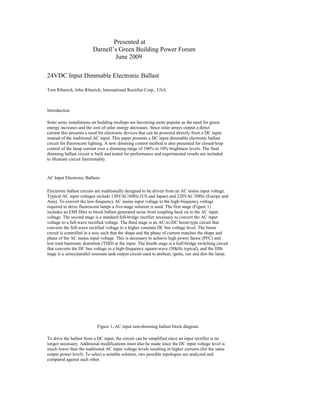
1. Presented at
Darnell’s Green Building Power Forum
June 2009
24VDC Input Dimmable Electronic Ballast
Tom Ribarich, John Ribarich, International Rectifier Corp., USA
Introduction
Solar array installations on building rooftops are becoming more popular as the need for green
energy increases and the cost of solar energy decreases. Since solar arrays output a direct
current this presents a need for electronic devices that can be powered directly from a DC input
instead of the traditional AC input. This paper presents a DC input dimmable electronic ballast
circuit for fluorescent lighting. A new dimming control method is also presented for closed-loop
control of the lamp current over a dimming range of 100% to 10% brightness levels. The final
dimming ballast circuit is built and tested for performance and experimental results are included
to illustrate circuit functionality.
AC Input Electronic Ballasts
Electronic ballast circuits are traditionally designed to be driven from an AC mains input voltage.
Typical AC input voltages include 120VAC/60Hz (US and Japan) and 220VAC/50Hz (Europe and
Asia). To convert the low-frequency AC mains input voltage to the high-frequency voltage
required to drive fluorescent lamps a five-stage solution is used. The first stage (Figure 1)
includes an EMI filter to block ballast generated noise from coupling back on to the AC input
voltage. The second stage is a standard full-bridge rectifier necessary to convert the AC input
voltage to a full-wave rectified voltage. The third stage is an AC-to-DC boost-type circuit that
converts the full-wave rectified voltage to a higher constant DC bus voltage level. The boost
circuit is controlled in a way such that the shape and the phase of current matches the shape and
phase of the AC mains input voltage. This is necessary to achieve high power factor (PFC) and
low total harmonic distortion (THD) at the input. The fourth stage is a half-bridge switching circuit
that converts the DC bus voltage to a high-frequency square-wave (50kHz typical), and the fifth
stage is a series/parallel resonant tank output circuit used to preheat, ignite, run and dim the lamp.
Figure 1, AC input non-dimming ballast block diagram.
To drive the ballast from a DC input, the circuit can be simplified since an input rectifier is no
longer necessary. Additional modifications must also be made since the DC input voltage level is
much lower than the traditional AC input voltage levels resulting in higher currents (for the same
output power level). To select a suitable solution, two possible topologies are analyzed and
compared against each other.
2. DC Input Electronic Ballast Solutions (Boost versus Push-Pull)
Two possible circuit topologies include a boost-type circuit followed by a half-bridge resonant
output stage, or, a push-pull step-up circuit followed by a resonant output stage. The boost
configuration is the same as the AC input solution (Figure 1) except that the rectifier stage can
now be eliminated. The DC input goes to the EMI filter and then directly to the boost stage. The
24VDC is then boosted up to a higher DC bus voltage (400VDC) and then converted into a high-frequency
square-wave by the half-bridge switching circuit. The square-wave voltage then feeds
the resonant output circuit that is used to drive the lamp. The push-pull configuration (Figure 2)
uses a step-up transformer to convert the 24VDC input voltage directly to a high-voltage/high-frequency
square-wave in a single step.
Figure 2, DC input, non-dimming push-pull ballast block diagram.
The boost configuration is similar to the AC input solution, except that the boost converter circuit
has to be re-dimensioned for the higher boost ratio and the power components need to be
rescaled to handle the higher current levels due to the lower input voltage. The boost
configuration has the advantage that the DC bus is regulated to a constant voltage, independent
of the DC input voltage, allowing the circuit to work over a wide range of input voltage. This could
be beneficial when driving the ballast from solar cells since the solar cell output voltage can vary
depending on the outside sunlight level and temperature. The disadvantage of the boost
configuration is the additional cost of the boost circuit, the high voltage rating of the switches, and
the decrease in efficiency due to the additional losses from the boost stage. The push-pull
configuration does the boost and DC-to-AC conversion in a single stage using a step-up
transformer driven by two primary windings. The push-pull configuration has the advantage that
the output is isolated from the input which may or may not be required when driving from solar
cells. The push-pull configuration also has the additional advantages of lower cost due to the
elimination of the boost circuit (but requires a step-up transformer), and lower voltage rated
switches. The disadvantage of the push-pull circuit is that the square-wave voltage feeding the
resonant tank will vary with the DC input voltage level which will limit the input voltage range.
However, the new dimming method described in the next section provides closed-loop control of
the lamp current which will help overcome the dependency on the DC input voltage and widen the
input voltage range. For these reasons, the push-pull configuration has been selected as the
topology to be used for the final ballast design. A comparison of the two topologies has been
summarized in Table I.
New Dimming Control Method
With the push-pull topology selected, the complete dimming design now includes (Figure 3) an
input filter for blocking ballast generated noise, a control IC and push-pull step-up circuit for
producing a high-frequency/high-voltage square-wave voltage, and a resonant output stage for
preheating, igniting and dimming the fluorescent lamp. The additional circuitry needed for
dimming includes (Figure 3) an isolated 0-to-10VDC dimming interface, a current-sensing circuit
to measure the lamp current, and a closed-loop feedback circuit to keep the lamp current
regulated to the user setting by continuously adjusting the output frequency. A closed-loop
3. system is needed to regulate the lamp current due to the non-linear electrical characteristics of
the fluorescent lamp.
DC Input
+-
EMI Filter Push-Pull Step-Up Tank Circuit Lamp
Frequency
Dimming
Reference
Feedback
Dimming Circuitry
Figure 3, DC input push-pull dimming ballast block diagram.
The new dimming control method includes the lamp current sensing circuit and the closed-loop
feedback circuit. A current sense resistor (RCS) is used to measure the AC lamp current (Figure
4). This AC measurement is then coupled to the DC reference through a feedback capacitor and
resistor (CFB, RFB). The resulting AC+DC signal is then compared to COM and the frequency is
controlled such that the valleys of the AC component are held at COM continuously (Figure 4). If
the DC reference is increased, the valley of the AC+DC signal will increase above COM and the
feedback circuit will decrease the frequency to increase the gain of the resonant tank. This will
increase the lamp current, as well as the amplitude of the AC+DC signal at the DIM pin, until the
valley reaches COM again. If the DC reference is decreased, the valley will decrease below COM.
The feedback circuit will then increase the frequency to decrease the gain of the resonant tank
until the valley reaches COM again. By combining the DC reference with the AC lamp current, a
single node can then be used for both reference and feedback functions to achieve closed-loop
dimming control.
Dimming
Reference and
Feedback
VREF
VREF
t
R1 CFB RFB
CDIM RCS
Current
Sensing
AC Lamp
Current
VRCS
t
VREF+VRCS
VREF100%
VREF10%
t
Figure 4, New AC+DC dimming control method.
4. To preheat, ignite and dim the lamp, the operating frequency is used as the control parameter.
During preheat and before the lamp ignites, the resonant tank circuit is a series L-C with a high-Q
(Figure 5). During dimming, the resonant tank circuit is a series L, parallel R-C, with a low-Q at
high dimming levels (100%) and a high-Q at low dimming levels (10%).
Vout
Vin
High-Q
Ignition
10%
ea
eh
Pr
t
50%
100%
Low-Q
Start
fmin f100% f50% f10% fmax Frequency
Figure 5, Resonant tank Bode plot with dimming operating points.
During preheat, the output frequency starts at a maximum level and is then decreased linearly
(Figure 6). As the frequency decreases, the lamp filaments are preheated by the resonant tank
circulating current. As the frequency decreases further towards the resonance frequency of the
resonant tank circuit the output voltage across the lamp increases. The lamp ignites when the
output voltage exceeds the lamp ignition threshold voltage. Lamp current begins to flow and the
closed-loop feedback circuit controls the lamp current to the desired dimming level.
Figure 6, Preheat, ignition and dimming timing diagram.
30W Dimming Ballast Design
5. The complete schematic is shown in Figure 7. The 24VDC input voltage first goes
through the EMI filter (CF and LF) followed by the dc bus capacitor (CBUS). The push-pull
switching stage (M1 and M2) is controlled by the IRS2530D IC for preheating, igniting and
dimming the lamp. Resistor RS provides the necessary current for the VCC supply of the IC. The
drains of the push-pull MOSFETs are connected to a centered-tapped primary winding of the
step-up transformer (TSU). The 24VDC bus is then stepped-up and converted to a high-frequency,
300Vp-p square-wave voltage across the secondary winding, which is used to drive
the resonant output stage. The resonant tank circuit (LRES and CRES) provides the necessary
transfer function for generating high voltages for lamp ignition and low-pass filtering for dimming.
A dc blocking capacitor (CDC) ensures that the lamp current is always AC to prevent mercury
migration which can cause lamp end blackening and a shortened lamp life. Secondary windings
from the resonant inductor (LRES:A,B) and capacitors (CH1 and CH2) are used to heat the lamp
filaments during preheat and dimming. The filament heating circuits also separate the lamp
current from the filament current allowing for a single current-sensing resistor (RCS) to be used to
sense the lamp current. The AC lamp current measurement across RCS is coupled to the DIM
pin through a feedback capacitor and resistor (CFB and RFB). Finally, resistors RSD1 and RSD2
are used to detect if the lamp has been removed and to automatically restart the ballast when the
lamp is re-inserted. Protection against all other ballast fault conditions such as failure to strike,
open filament, and input voltage brown-out, are included internally to the IRS2530D to further
reduce component count and increase reliability.
IRS2530D
Figure 7, Dimming mini-ballast circuit schematic.
The measured ballast waveforms are shown in Figure 6. Figure 6A shows the VCO pin
voltage, lamp voltage and lamp current during normal preheat, ignition and dimming modes. The
VCO pin and lamp voltage ramp up during preheat and ignition to preheat the lamp filaments and
then to ignite the lamp when the lamp ignition voltage threshold is reached. Lamp current starts to
flow immediately after ignition at the start of dimming. Figures 6B and 6C show the half-bridge
output voltage (VS) together with the DIM pin voltage during 100% and 10% dimming conditions.
The DIM pin voltage amplitude decreases (together with the lamp current) from 100% down to
6. 10% and the operating frequency is continuously adjusted to keep the valley of the sinusoid
regulated at COM.
(A)
(B)
Figure 6, Mini-ballast measured waveforms.
(C)
The 0 to 10VDC user dimming input voltage versus the r.m.s. lamp output current (Figure
7) shows good linearity over the entire dimming range.
0.25
0.2
Lamp Current
[A] 0.15
0.1
0.05
0
0 1 2 3 4 5 6 7 8 9 10
Dimming Input Voltage [VDC]
Figure 7, Dimming input versus lamp current output graph.
Conclusion
7. Electronic ballasts driven off of a DC input have the advantages of no input rectification required
and no PFC stage required. Simplifying the design further using a three-stage push-pull topology
has the additional benefits of eliminating the boost stage to reduce cost, providing isolation, and
increasing lumens/watt. The new closed-loop lamp current control method maintains good
regulation of the lamp current and therefore allows for a wide DC input voltage range without the
need for a constant DC bus voltage. The final ballast design performs well over the complete
input voltage range, including dimming and protection against all fault conditions.
Further improvements to the design for consideration include adding an auxiliary supply for VCC
to achieve a lower DC input voltage level. Also, the same solution can also be used for HID and
LED lighting applications.
References
1)
2)
3)
4)
5)
P. Green, AN-1038: Low Voltage DC Supply Dimmable Ballast for 1x36W Lamp,
http://www.irf.com/technical-info/appnotes/an-1038.pdf.
IRS2530D Dimming Ballast Control IC, Datasheet, www.irf.com.
T. Ribarich, J. Ribarich, A New Model for High-Frequency Ballast Design, in IEEE-IAS
Conf. Rec., 1997, pp. 2334-2339.
International Rectifier, IRPLDIM4E and IRPLDIM5E, Reference Design Kits, 2009,
www.irf.com.
Elenbaas, W., ed., Fluorescent Lamps, Second Edition, Philips Technical Library,
Eindhoven, The Netherlands 1971.