Microcontrollers have the following key features:
- They integrate CPU, memory and I/O on a single chip, allowing them to function as standalone computers.
- They are field programmable via EPROM or E2PROM, providing flexibility.
- They have low cost, small size, reliability, and ease of troubleshooting compared to microprocessor-based systems.
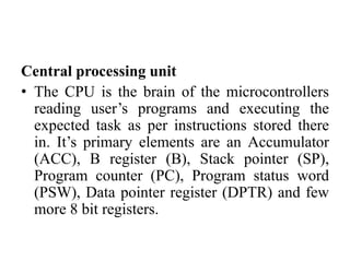
The 8051 microcontroller architecture has an 8-bit CPU, 64KB program memory, 128 bytes internal RAM, 32 I/O pins, two timers, serial port, and five interrupt sources. It uses various registers, addressing modes, and has instruction sets for data transfer, arithmetic, logical operations and program branching.


![Attack surfaces and attack tress[inform]](https://cdn.slidesharecdn.com/ss_thumbnails/lecture03-260108015941-a4dee53b-thumbnail.jpg?width=640&height=640&fit=bounds)


