![Crystal Structure using X – ray Diffraction X-rays of the order of 1Ǻ wavelength are used to probe the structural information in solid Interatomic distances a few Ǻ ( m,n,p) are coordinates of a point [100] represents the direction of the vector from origin to (1,0,0) Miller Indices are h,k, l if 1/h, 1/k, 1/ l are the intercepts along X,Y,Z axes Cubic : {100} = (100), (010),(001), (100), (010),(001) Tetragonal :{ 100} = (100), (010), (100), (010) (100) (001) 0 (200) X Y Z (1,0,0) Cubic unit cell](https://image.slidesharecdn.com/1-crystalstructureusingxraydiffraction-111116052913-phpapp01/85/1-crystal-structure-using-x-ray-diffraction-1-320.jpg)
![Crystal Structure using X – ray Diffraction X-rays of the order of 1Ǻ wavelength are used to probe the structural information in solid Interatomic distances a few Ǻ ( m,n,p) are coordinates of a point [100] represents the direction of the vector from origin to (1,0,0) Miller Indices are h,k, l if 1/h, 1/k, 1/ l are the intercepts along X,Y,Z axes Cubic : {100} = (100), (010),(001), (100), (010),(001) Tetragonal :{ 100} = (100), (010), (100), (010) (100) (001) 0 (200) X Y Z (1,0,0) Cubic unit cell](https://image.slidesharecdn.com/1-crystalstructureusingxraydiffraction-111116052913-phpapp01/75/1-crystal-structure-using-x-ray-diffraction-1-2048.jpg)
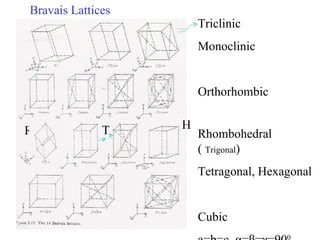
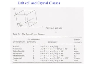
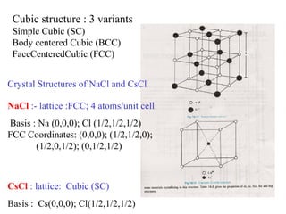
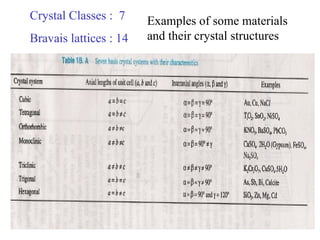
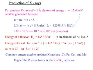
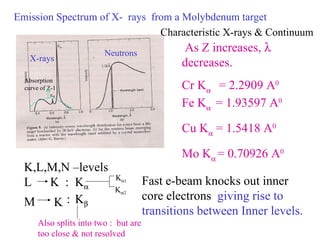
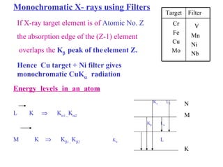
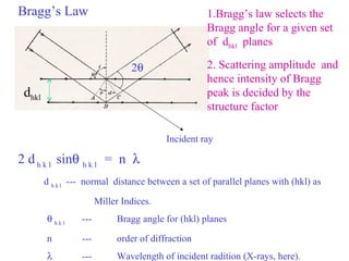
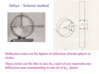
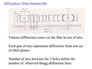
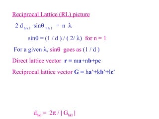
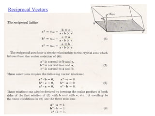
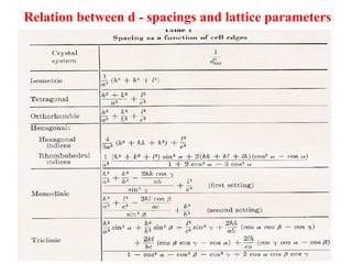
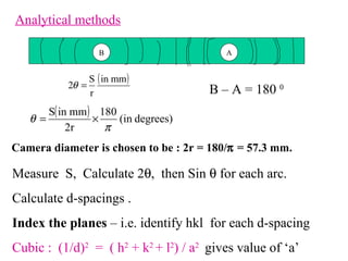
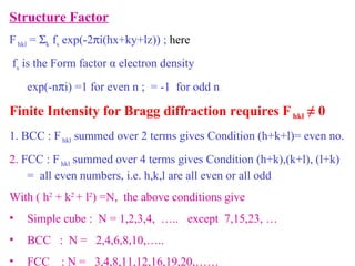
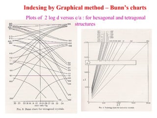
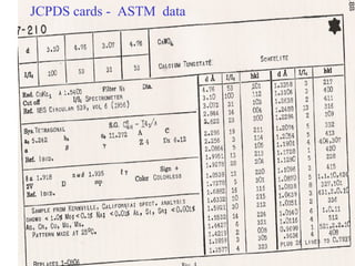
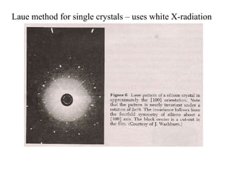
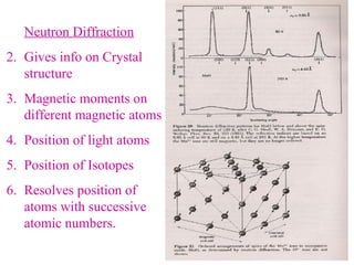

The document discusses crystal structure determination using X-ray diffraction. It describes how X-rays are used to probe interatomic distances in solids and explains key concepts like Bragg's law, reciprocal lattices, and Miller indices that are used to index diffraction patterns and determine unit cell parameters and crystal structures. Examples of common crystal structures like NaCl, CsCl are given along with methods to analyze diffraction data.


