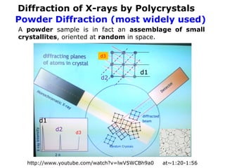
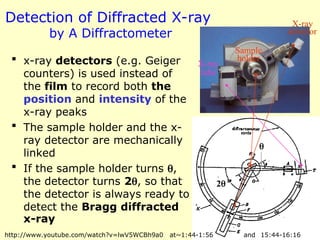
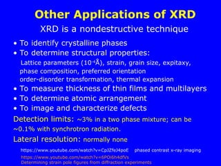
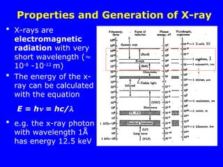
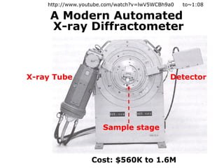
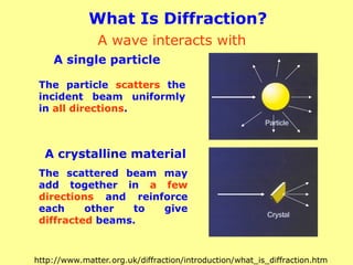
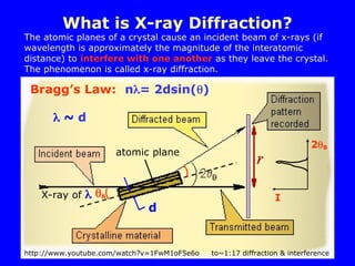
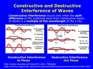
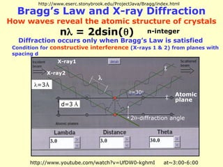
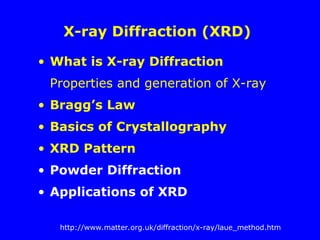
The document provides a comprehensive overview of X-ray diffraction (XRD), including the properties and generation of X-rays, Bragg’s law, and basics of crystallography. It details the principles behind X-ray production, diffraction patterns, and their applications in analyzing crystalline materials through mechanisms like constructive interference. Additionally, it discusses the significance of characteristics such as peak position, width, and intensity in determining lattice parameters and crystal structures.
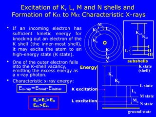
![Basics of Crystallography
A crystal consists of a periodic arrangement of the unit cell
into a lattice. The unit cell can contain a single atom or
atoms in a fixed arrangement.
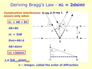
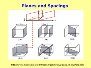
Crystals consist of planes of atoms that are spaced a
distance d apart, but can be resolved into many atomic
planes, each with a different d-spacing.
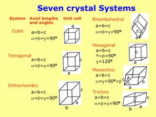
a,b and c (length) and , and (angles between a,b and c)
are lattice constants or parameters which can be
determined by XRD.
smallest building block
Unit cell (Å)
Lattice
CsCl
d1
d2
d3
a
b
c
z [001]
y [010]
x [100] crystallographic
axes
Single crystal
http://www.youtube.com/watch?v=Rm-i1c7zr6Q&list=TLyPTUJ62VYE4wC1snHSChDl0NGo9IK-Nl
http://www.youtube.com/watch?v=Mm-jqk1TeRY crystal packing in lattices
to~2:25
Lattice structures](https://image.slidesharecdn.com/lecture-6xrd1-240821145046-3468757d/85/Lecture-presentation-on-x-ray-diffraction-ppt-22-320.jpg)
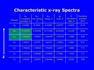
![Indexing of Planes and Directions
a
b
c
a
b
c
(111)
[110]
a direction [uvw]
a set of equivalent
directions <uvw>
<100>:[100],[010],[001]
[100],[010] and [001]
a plane (hkl)
a set of equivalent
planes {hkl}
{110}:(101),(011),(110)
(101),(101),(101),etc.
(110)
[111]
http://www.youtube.com/watch?v=9Rjp9i0H7GQ Directions in crystals](https://image.slidesharecdn.com/lecture-6xrd1-240821145046-3468757d/85/Lecture-presentation-on-x-ray-diffraction-ppt-27-320.jpg)
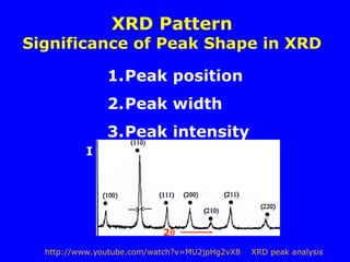
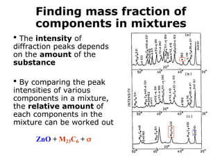
![Peak Intensity
X-ray intensity: Ihkl lFhkll2
Fhkl - Structure Factor
Fhkl = fjexp[2i(huj+kvj+lwj)]
j=1
N
fj – atomic scattering factor
fj Z, sin/
N – number of atoms in the unit cell,
uj,vj,wj - fractional coordinates of the j
th atom
in the unit cell
Low Z elements may be difficult to detect by XRD
Determine crystal structure and atomic arrangement
in a unit cell](https://image.slidesharecdn.com/lecture-6xrd1-240821145046-3468757d/85/Lecture-presentation-on-x-ray-diffraction-ppt-31-320.jpg)
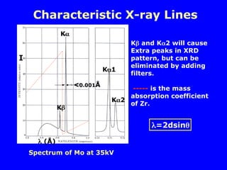
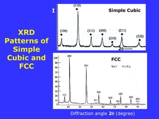
![Cubic Structures
a = b = c = a
Simple Cubic Body-centered Cubic Face-centered Cubic
BCC FCC
8 x 1/8 =1 8 x 1/8 + 1 = 2 8 x 1/8 + 6 x 1/2 = 4
1 atom 2 atoms 4 atoms
a
a
a
[001]
z axis
[100]
x
[010]
y
Location: 0,0,0 0,0,0, ½, ½, ½, 0,0,0, ½, ½, 0,
½, 0, ½, 0, ½, ½,
- corner atom, shared with 8 unit cells
- atom at face-center, shared with 2 unit cells
8 unit cells](https://image.slidesharecdn.com/lecture-6xrd1-240821145046-3468757d/85/Lecture-presentation-on-x-ray-diffraction-ppt-32-320.jpg)
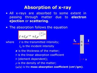
![Structures of Some Common Metals
BCC FCC
a
a
a
[001] axis
[100]
[010]
(001) plane
(002)
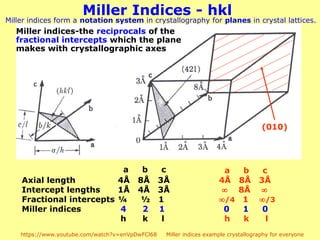
h,k,l – integers, Miller indices, (hkl) planes
(001) plane intercept [001] axis with a length of a, l = 1
(002) plane intercept [001] axis with a length of ½ a, l = 2
(010) plane intercept [010] axis with a length of a, k = 1, etc.
(010)
plane
½ a [010]
axis
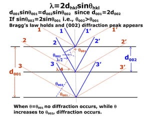
= 2dhklsinhkl
Mo Cu
d002 =
d001
d010](https://image.slidesharecdn.com/lecture-6xrd1-240821145046-3468757d/85/Lecture-presentation-on-x-ray-diffraction-ppt-33-320.jpg)
![For a certain set of plane, (hkl)
F = f () exp[2i(hu+kv+lw)]
= f () exp[2i(hu+kv+lw)]
= f (){exp[2i(0)] + exp[2i(h/2 + l/2)]
+ exp[2i(h/2 + k/2)] + exp[2i(k/2 + l/2)]}
= f (){1 + ei(h+k)
+ ei(k+l)
+ ei(l+h)
}
Since e2ni
= 1 and e(2n+1)i
= -1,
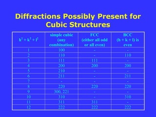
if h, k & l are all odd or all even, then (h+k),
(k+l), and (l+h) are all even and F = 4f;
otherwise, F = 0
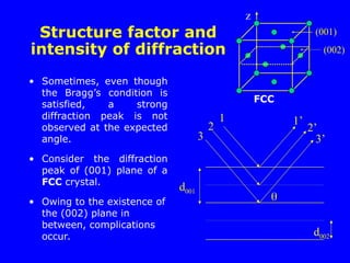
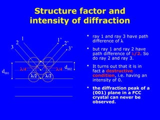
Structure factor and intensity of
diffraction for FCC
mixed
l
k,
h,
0
even
all
or
odd
all
l
k,
h,
4 f
F
j
j
j lw
kv
hu
i
j
j e
f
F
2
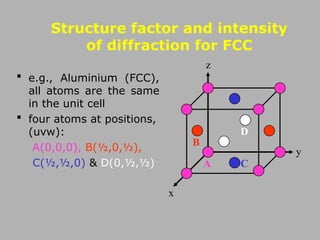
A(0,0,0), B(½,0,½),
C(½,½,0) & D(0,½,½)
2i
Ihkl lFhkll2](https://image.slidesharecdn.com/lecture-6xrd1-240821145046-3468757d/85/Lecture-presentation-on-x-ray-diffraction-ppt-38-320.jpg)
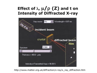
![Diffraction of X-rays by Crystals-Laue Method
Back-reflection Laue
Film
X-ray
crystal
crystal Film
Transmission Laue
[001]
http://www.youtube.com/watch?v=UfDW0-kghmI at~1:20-3:00
http://www.youtube.com/watch?v=2JwpHmT6ntU](https://image.slidesharecdn.com/lecture-6xrd1-240821145046-3468757d/85/Lecture-presentation-on-x-ray-diffraction-ppt-46-320.jpg)