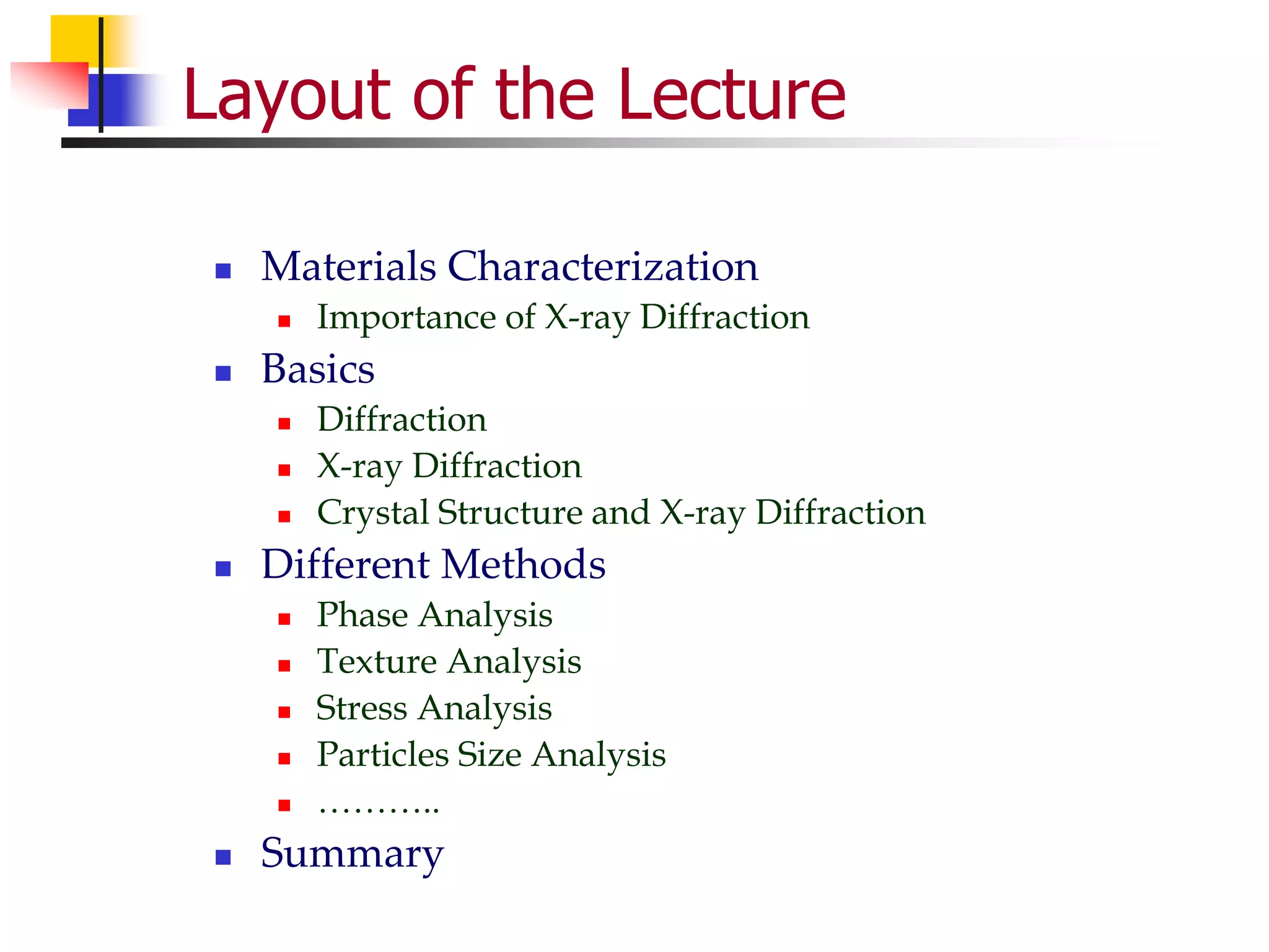
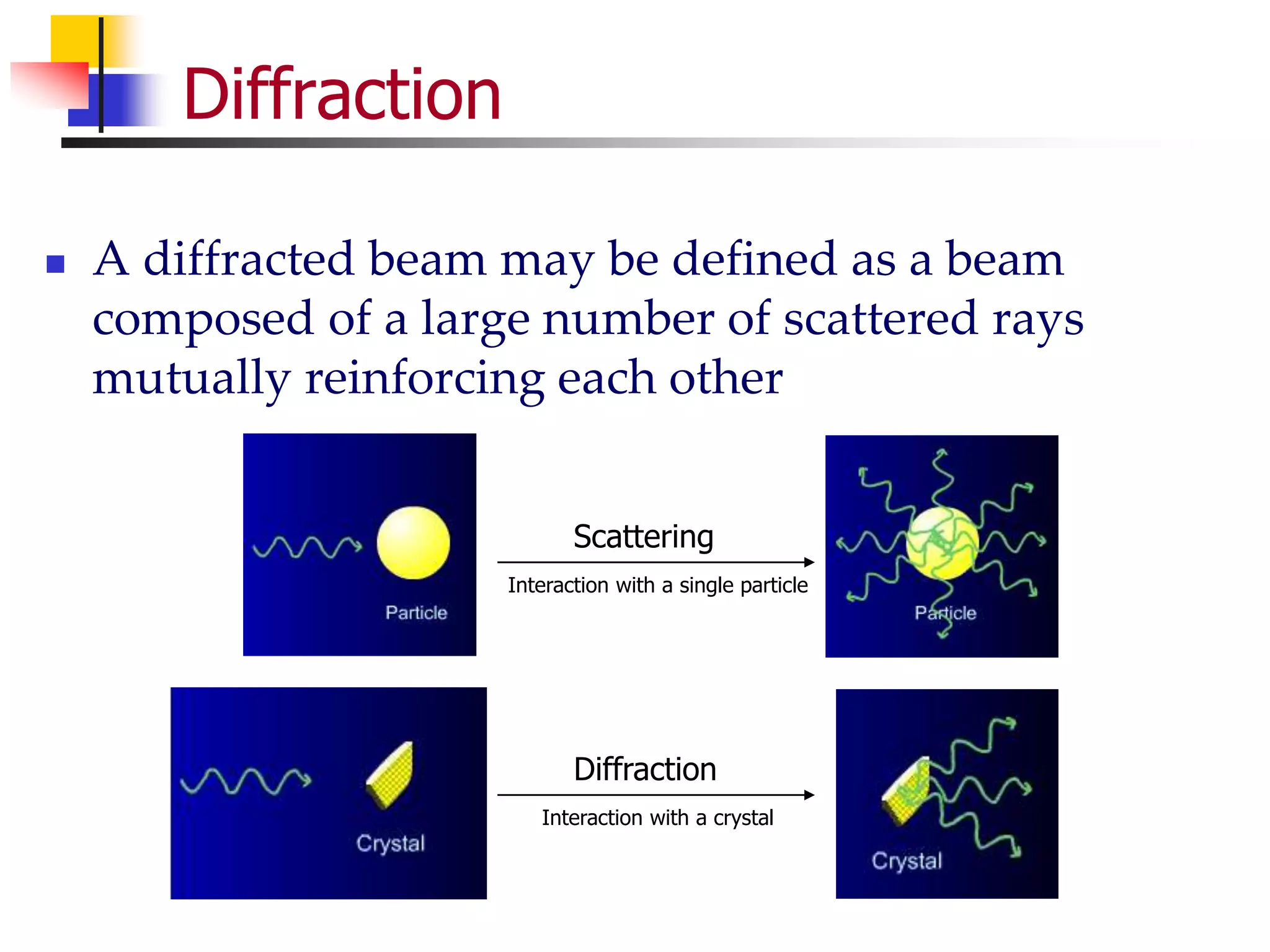
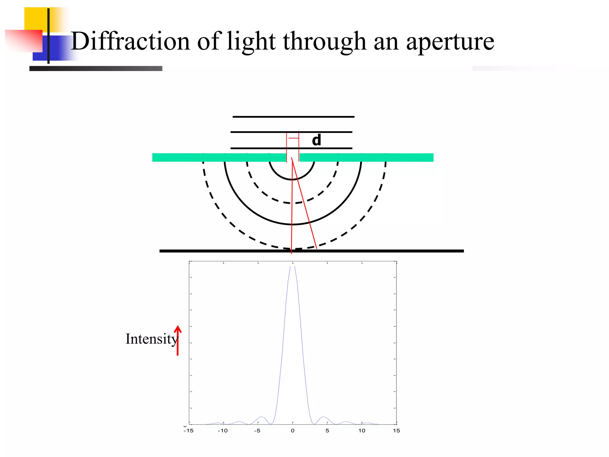
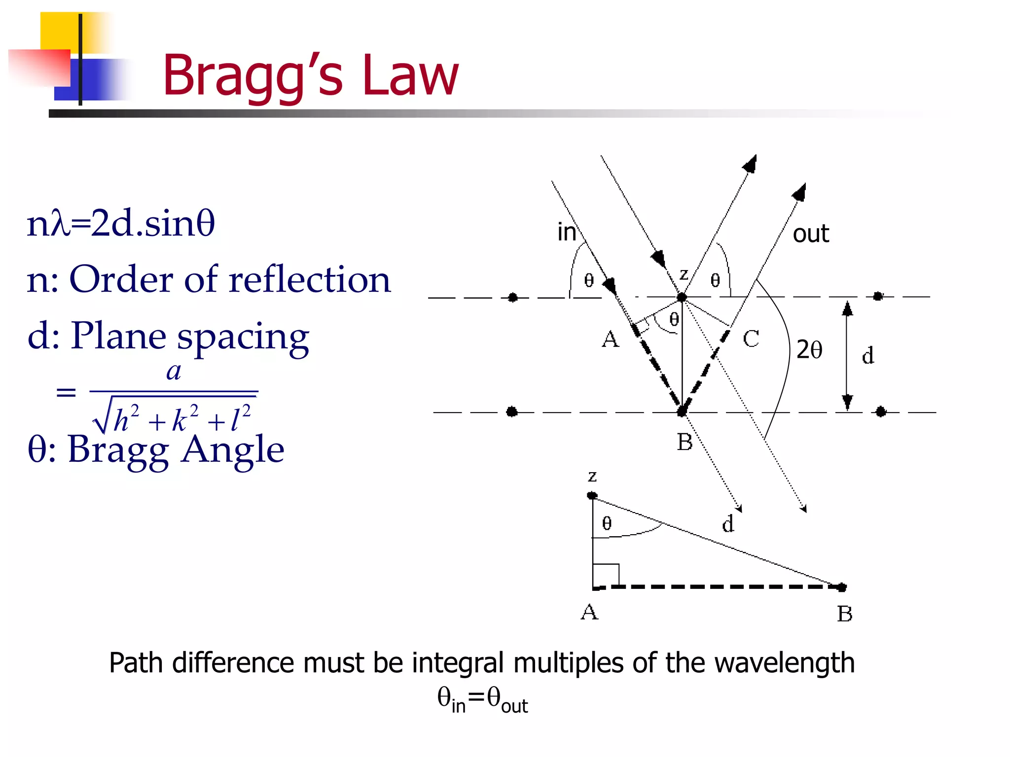
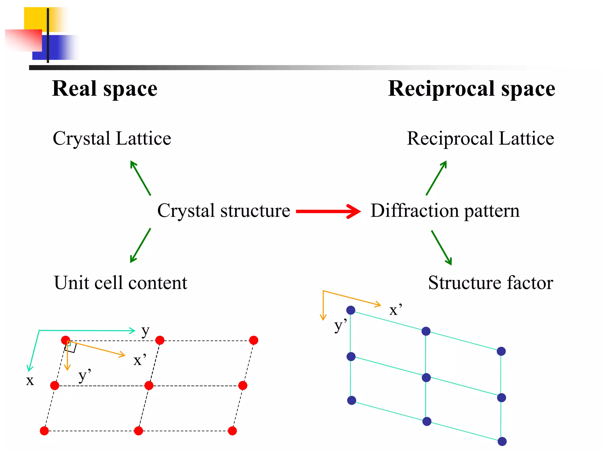
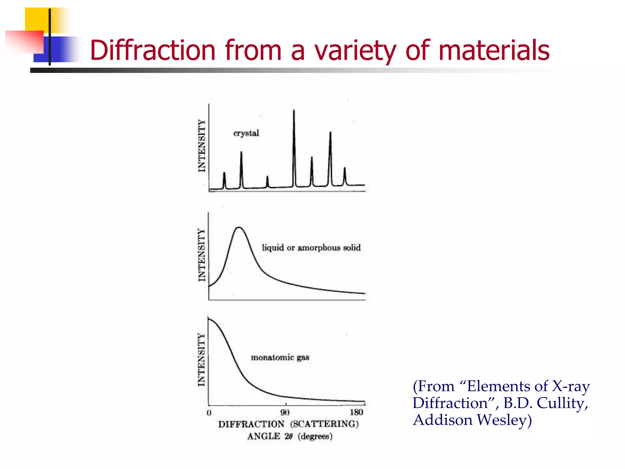
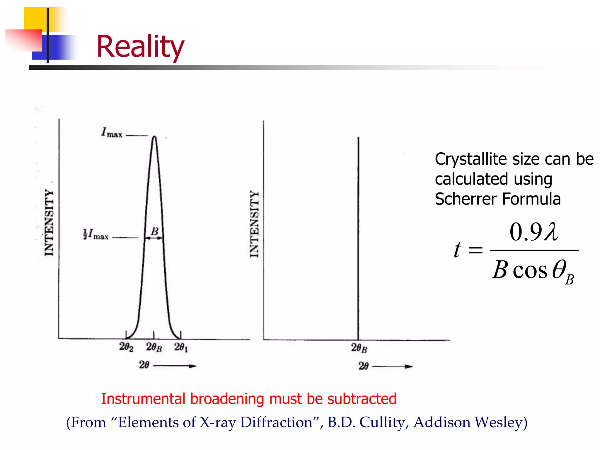
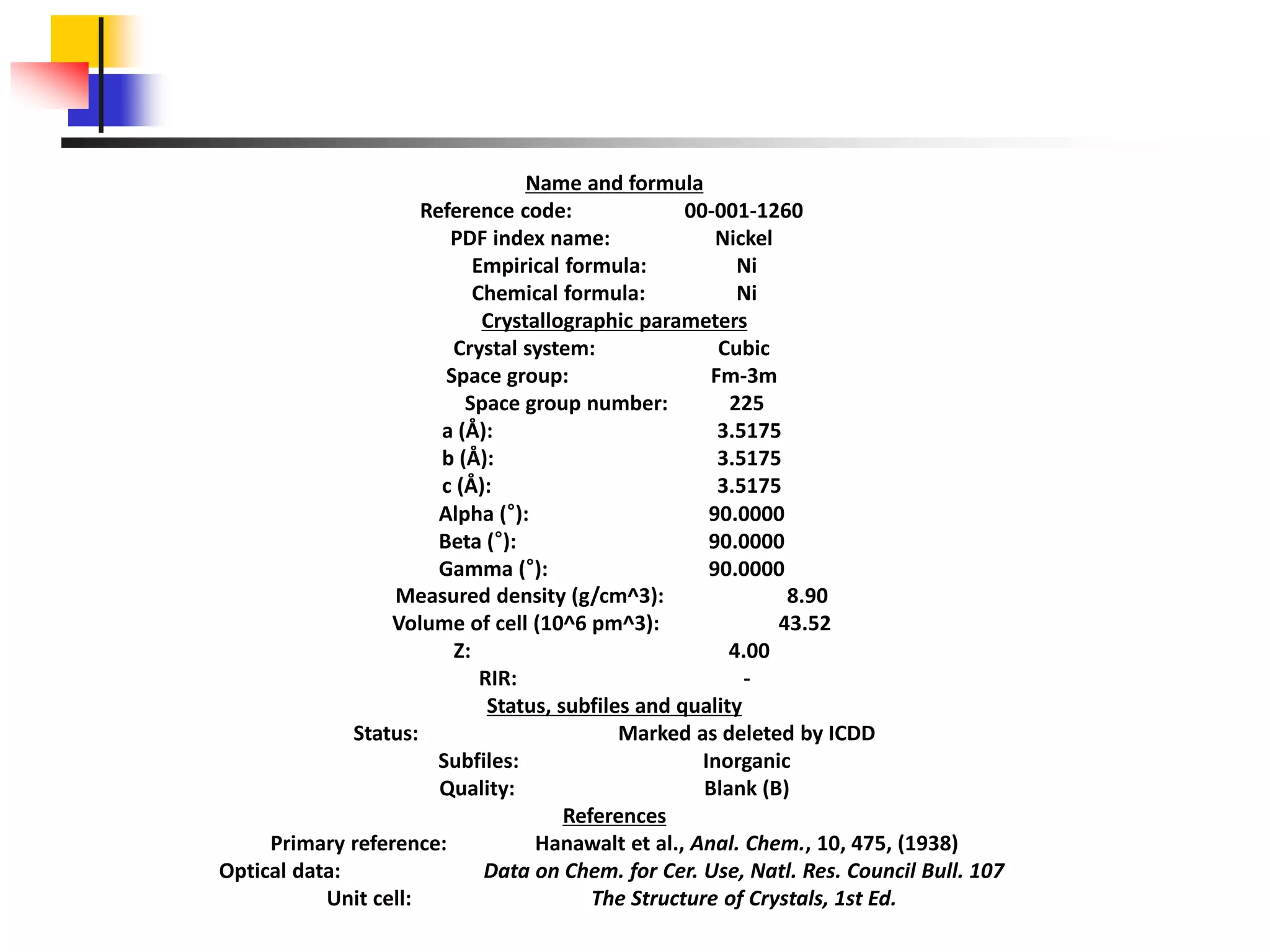
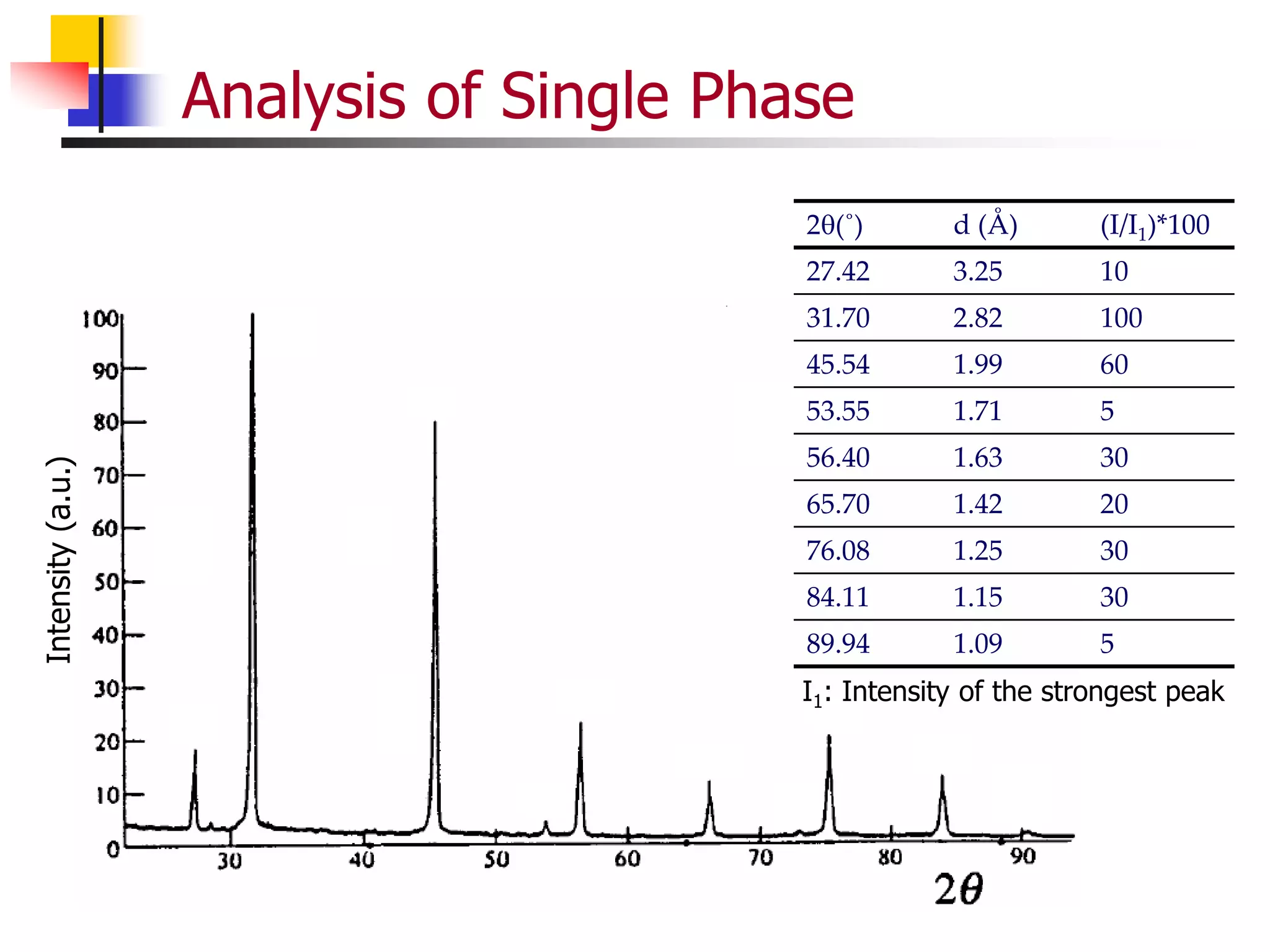
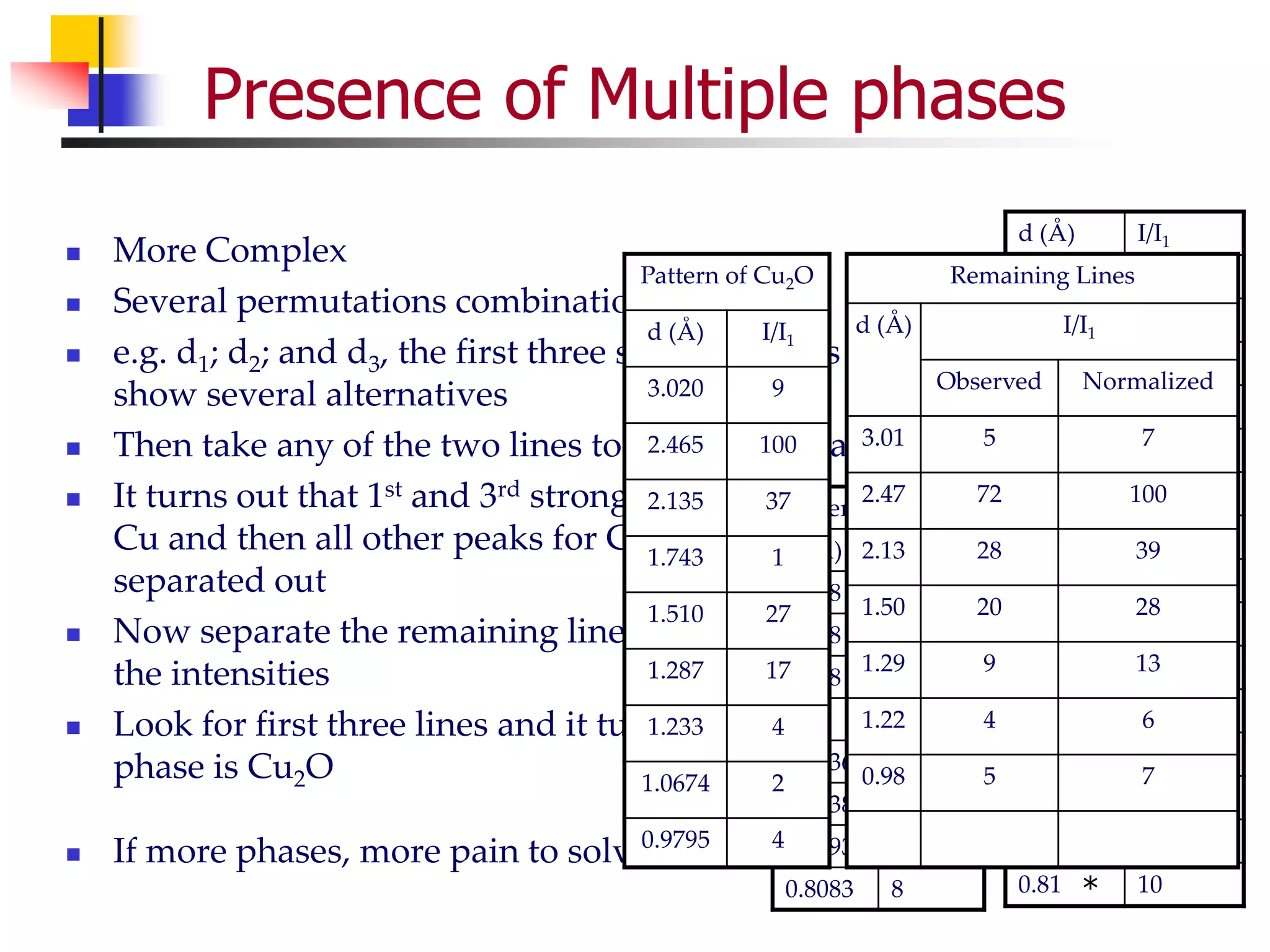
This document provides an overview of x-ray diffraction principles and practices. It begins with an introduction to materials characterization and the importance of x-ray diffraction. It then covers the basics of diffraction and Bragg's law. The document discusses different x-ray diffraction methods and techniques for analyzing crystal structure, phase, texture, stress, and particle size. It provides examples of analyzing diffraction patterns from single and multiple phases. Finally, it touches on concepts like broadening, texture, and pole figures.


![Texture
Fiber Texture
A particular direction [uvw] for all grains is more or less parallel to
the wire or fiber axis
e.g. [111] fiber texture in Al cold drawn wire
Double axis is also possible
Example: [111] and [100] fiber textures in Cu wire
Sheet Texture
Most of the grains are oriented with a certain crystallographic plane
(hkl) roughly parallel to the sheet surface and certain direction [uvw]
parallel to the rolling direction
Notation: (hkl)[uvw]](https://image.slidesharecdn.com/termprojectsaxs-230209084404-1883ec68/75/Small-angle-X-ray-Diffraction-43-2048.jpg)
![Texture in materials
[uvw] i.e. perpendicular to
the surface of all grains is
parallel to a direction [uvw]
Also, if the direction [u1v1w1]
is parallel for all regions, the
structure is like a single
crystal
However, the direction [u1v1w1]
is not aligned for all regions,
the structure is like a mosaic
structure, also called as
Mosaic Texture](https://image.slidesharecdn.com/termprojectsaxs-230209084404-1883ec68/75/Small-angle-X-ray-Diffraction-44-2048.jpg)
![Degree of orientation
Substrate
Film
Side view
[uvw] corresponding
to planes parallel to
the surface
But what if the planes when looked from top have random orientation?
Top view](https://image.slidesharecdn.com/termprojectsaxs-230209084404-1883ec68/75/Small-angle-X-ray-Diffraction-45-2048.jpg)


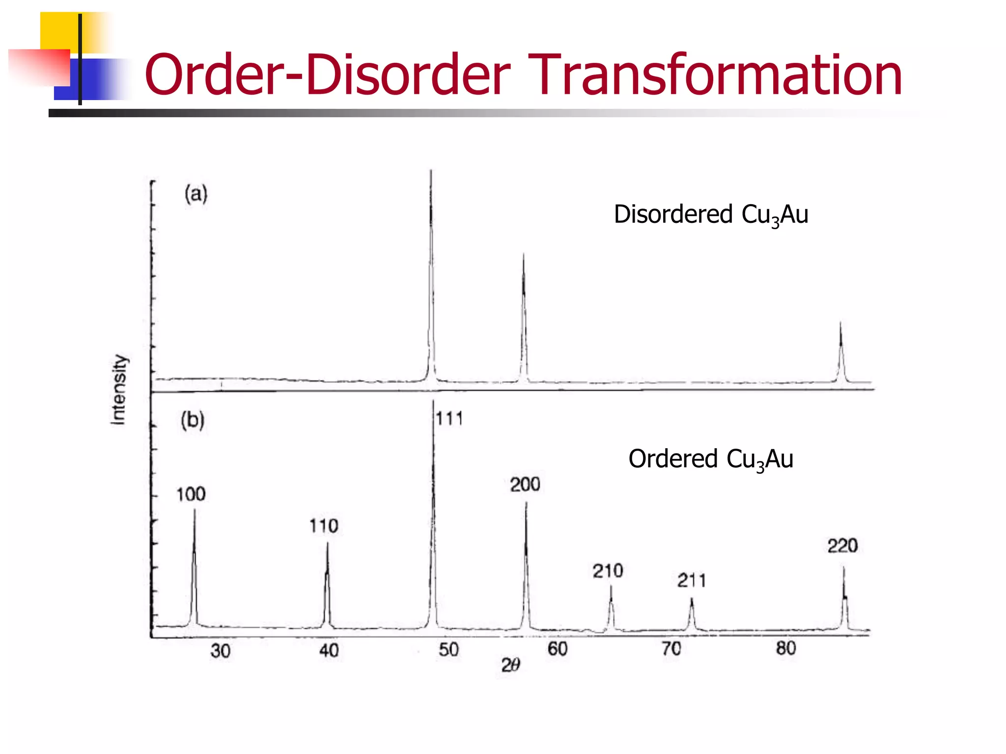
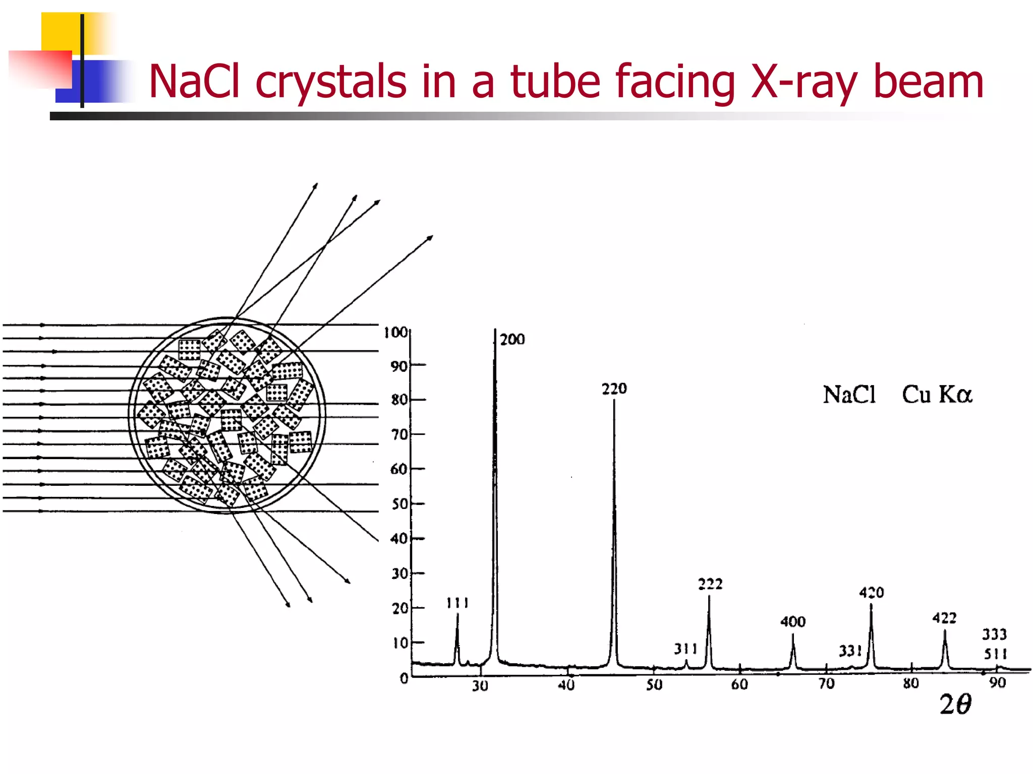
![Order Disorder Transformation
Structure factor is dependent on the presence
of order or disorder within a material.
Complete Disorder
Example: AB with A and B atoms
randomly distributed in the lattice
Lattice positions: (000) and (½ ½ ½)
Atomic scattering factor
favj= ½ (fA+fB)
Structure Factor, F, is given by
F = Σf exp[2i (hu+kv+lw)]
= favj [1+e( i (h+k+l))]
= 2. favj when h+k+l is even
= 0 when h+k+l is odd
The expected pattern is like a BCC crystal
A
B](https://image.slidesharecdn.com/termprojectsaxs-230209084404-1883ec68/75/Small-angle-X-ray-Diffraction-49-2048.jpg)
![Order Disorder Transformation
Complete Order
Example: AB with A at (000) and B at (½ ½ ½)
Structure Factor, F, is given by
F = fA e[2i (h.0+k.0+l.0)]+ fA e[2i (h. ½+k. ½+l. ½)]
= fA+fB when h+k+l is even
= fA-fB when h+k+l is odd
The expected pattern is not like a BCC crystal,
rather like a simple cubic crystal where all the
reflections are present.
Extra reflections present are called as
superlattice reflections
A
B](https://image.slidesharecdn.com/termprojectsaxs-230209084404-1883ec68/75/Small-angle-X-ray-Diffraction-50-2048.jpg)