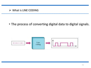
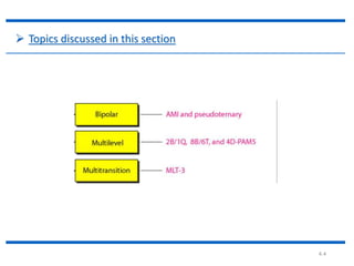
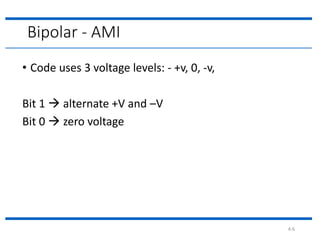
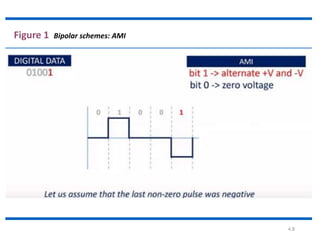
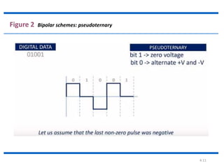
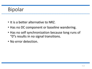
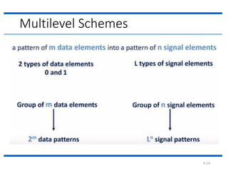
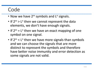
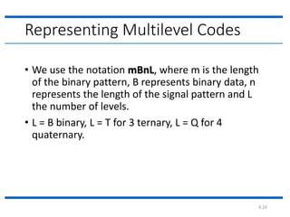
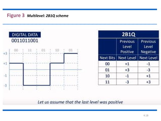
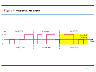
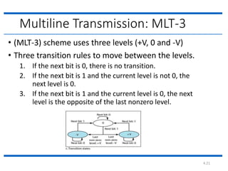
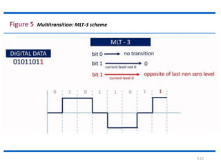
Line Coding
By
Md. Fazle Rabbi
16CSE057
4.2
 What is LINE CODING
• The process of converting digital data to digital signals.
4.3
 Types of line Coding
4.4
 Topics discussed in this section
4.5
Bipolar – AMI (Alternate Mark Inversion)
4.6
Bipolar - AMI
• Code uses 3 voltage levels: - +v, 0, -v,
Bit 1  alternate +V and –V
Bit 0  zero voltage
4.7
Example
4.8
Figure 1 Bipolar schemes: AMI
4.9
Bipolar - Pseudoternary
• Code uses 3 voltage levels: - +v, 0, -v,
Bit 1  zero voltage
Bit 0  alternate +V and –V
4.10
Example
4.11
Figure 2 Bipolar schemes: pseudoternary
4.12
Bipolar
• It is a better alternative to NRZ.
• Has no DC component or baseline wandering.
• Has no self synchronization because long runs of
“0”s results in no signal transitions.
• No error detection.
4.13
Multilevel
4.14
Multilevel Schemes
4.15
Code
• Now we have 2m symbols and Ln signals.
• If 2m > Ln then we cannot represent the data
elements, we don’t have enough signals.
• If 2m = Ln then we have an exact mapping of one
symbol on one signal.
• If 2m < Ln then we have more signals than symbols
and we can choose the signals that are more
distinct to represent the symbols and therefore
have better noise immunity and error detection as
some signals are not valid.
4.16
Representing Multilevel Codes
• We use the notation mBnL, where m is the length
of the binary pattern, B represents binary data, n
represents the length of the signal pattern and L
the number of levels.
• L = B binary, L = T for 3 ternary, L = Q for 4
quaternary.
4.17
2B1Q
Example
4.18
Figure 3 Multilevel: 2B1Q scheme
4.19
Redundancy
• In the 2B1Q scheme we have no redundancy and
we see that a DC component is present.
• If we use a code with redundancy we can decide to
use only “0” or “+” weighted codes (more +’s than
-’s in the signal element) and invert any code that
would create a DC component. E.g. ‘+00++-’ -> ‘-
00--+’
• Receiver will know when it receives a “-” weighted
code that it should invert it as it doesn’t represent
any valid symbol.
4.20
Figure 4 Multilevel: 8B6T scheme
4.21
Multiline Transmission: MLT-3
• (MLT-3) scheme uses three levels (+V, 0 and -V)
• Three transition rules to move between the levels.
1. If the next bit is 0, there is no transition.
2. If the next bit is 1 and the current level is not 0, the
next level is 0.
3. If the next bit is 1 and the current level is 0, the next
level is the opposite of the last nonzero level.
4.22
Example
4.23
Figure 5 Multitransition: MLT-3 scheme
4.24
Thank you

3. line coding( bipolar, multilevel, multitransition)

  • 1.
  • 2.
    4.2  What isLINE CODING • The process of converting digital data to digital signals.
  • 3.
    4.3  Types ofline Coding
  • 4.
    4.4  Topics discussedin this section
  • 5.
    4.5 Bipolar – AMI(Alternate Mark Inversion)
  • 6.
    4.6 Bipolar - AMI •Code uses 3 voltage levels: - +v, 0, -v, Bit 1  alternate +V and –V Bit 0  zero voltage
  • 7.
  • 8.
  • 9.
    4.9 Bipolar - Pseudoternary •Code uses 3 voltage levels: - +v, 0, -v, Bit 1  zero voltage Bit 0  alternate +V and –V
  • 10.
  • 11.
    4.11 Figure 2 Bipolarschemes: pseudoternary
  • 12.
    4.12 Bipolar • It isa better alternative to NRZ. • Has no DC component or baseline wandering. • Has no self synchronization because long runs of “0”s results in no signal transitions. • No error detection.
  • 13.
  • 14.
  • 15.
    4.15 Code • Now wehave 2m symbols and Ln signals. • If 2m > Ln then we cannot represent the data elements, we don’t have enough signals. • If 2m = Ln then we have an exact mapping of one symbol on one signal. • If 2m < Ln then we have more signals than symbols and we can choose the signals that are more distinct to represent the symbols and therefore have better noise immunity and error detection as some signals are not valid.
  • 16.
    4.16 Representing Multilevel Codes •We use the notation mBnL, where m is the length of the binary pattern, B represents binary data, n represents the length of the signal pattern and L the number of levels. • L = B binary, L = T for 3 ternary, L = Q for 4 quaternary.
  • 17.
  • 18.
  • 19.
    4.19 Redundancy • In the2B1Q scheme we have no redundancy and we see that a DC component is present. • If we use a code with redundancy we can decide to use only “0” or “+” weighted codes (more +’s than -’s in the signal element) and invert any code that would create a DC component. E.g. ‘+00++-’ -> ‘- 00--+’ • Receiver will know when it receives a “-” weighted code that it should invert it as it doesn’t represent any valid symbol.
  • 20.
  • 21.
    4.21 Multiline Transmission: MLT-3 •(MLT-3) scheme uses three levels (+V, 0 and -V) • Three transition rules to move between the levels. 1. If the next bit is 0, there is no transition. 2. If the next bit is 1 and the current level is not 0, the next level is 0. 3. If the next bit is 1 and the current level is 0, the next level is the opposite of the last nonzero level.
  • 22.
  • 23.
  • 24.