This document presents a matrix converter topology for single-phase to three-phase AC power conversion for electric rail traction applications. The converter replaces the conventional multi-stage AC-DC-AC conversion with a single-stage direct AC-AC conversion. The matrix converter operation is analyzed using a separation and link approach, and sinusoidal pulse width modulation control is used. Simulation results show the feasibility of the matrix converter for retrofitting existing AC traction drive systems with a single-stage power conversion topology.
![Abstract—The paper presents the converter topology for single
to three phase matrix converter for the ac traction drives. The
converter analysis is presented with source separation and link
approach. The conventional carrier based control is employed for
the converter to control the output voltage and frequency. The
operational feasibility with the three phase ac traction motor (850
kW) is presented. The performance of the converter with the
motor is simulated in the PSIM. The results indicate the feasibility
of the matrix converter application to retrofit the existing (AC-
DC-AC) to (AC-AC) traction drive system.
Index Terms—Matrix Converters, Sinusoidal Pulse Width
Modulation, Traction Motors, Variable Speed Drives.
I. INTRODUCTION
ELECTRIC traction in most of the country have single
phase 25 kV, 50 Hz AC or 3kV DC power supply systems.
The conventional locomotives have a transformer with a tap
changer or a step- down transformer with semiconductor
devices, like power diodes, GTOs, IGBTs, etc.
Fig. 1: Conventional Single-to-three phase ac Traction.
Those are used for ac- to- dc and dc-to-three-phase ac power
conversion and to charge the intermediate dc-link capacitors
for energy storage elements. The locomotives have Bo-Bo (4-
TM on 4 axles) or Co-Co (6-TM on 6 axles) type bogie
1
Bhimrao S. Gajbhiye is research scholar at Visvesvaraya National
Institute of Technology, Nagpur, Maharashtra, India. (e-mail-
bsgajbhiye@gmail.com)
2
Dr. M. V. Aware is member IEEE and professor atVisvesvarayaNational
Institute of Technology, Nagpur, Maharashtra, India. (e-mail-
mva_win@yahoo.com)
3
Dr. B. S. Umre is member IEEE and assistant professor at Visvesvaraya
National Institute of Technology, Nagpur, Maharashtra, India. (e-mail-
bsumre@rediffmail.com)
4
Rajesh Patil is IRSEE Batch-1992 currently working as Sr.D.E.E.(Trd.)at
Central Railways, Nagpur,Maharashtra, India. (e-mail- rajpat@gmail.com)
arrangements. The traction motor (TM) is a three phase
induction motor operated with variable voltage and frequency
converter in conventional speed control mode as shown in
figure 1.
The converter without dc link will be preferred over the two
stage ac-dc-ac conversion in the existing power conversion
arrangements in the ac traction drives. The matrix converters
(MC) is a direct ac-to-ac converter, replaces the multiple
conversion stages and the intermediate energy storage
elements (dc-link) thus being a single stage converter as
shown in figure 2. The different topologies, single phase to
single phase and three phase to three phase with bi-directional
switches are analyzed and results are presented [1]-[2].The
phase transformation from single to three phase with three
legged six bi-directional switch converter having simple
control given for the three phase balanced loads [3]-[6].This
control suffers lower voltage utilization and requires
additional matching transformer. The matrix converter
topology could be analyzed through the separation and link
technique [4]. This analysis incorporates the back–to-back
common emitter bi-directional switch cells configuration is
shown in figure 2 with fictitious dc link to understand the
operation of matrix converter [5].
S1 S3
S6S4
Vs (t)
S5
S2
Sc1
Sc2
Sc1d
Sc2d
M
Ii (t)
a
b
c
A
B
C
+
Source Matrix converter Traction motor
Fig. 2: Proposed single-to-three phase ac Traction converter.
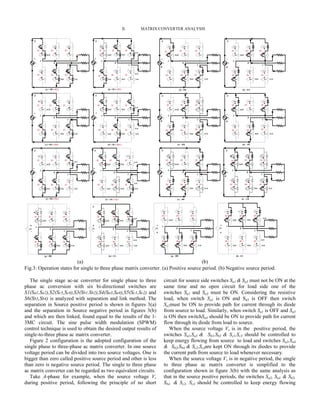
The paper proposes the single phase to three phase matrix
converter topology for traction drives. The operation of the
converter is analyzed using the separation and link approach.
The control is built by using the sinusoidal pulse width
modulation (SPWM) for the bi-directional switches in this
converter. This single phase to three phase converter has
following merits.
-This replaces the conventional ac-dc-ac stages so the
effective energy conversion is efficient.
-The control is conventional carrier based SPWM.
The known pattern of harmonics predicts the de-rating and
operational efficiency of the induction motor.
Single phase to three phase ac Matrix Converter
for Traction Drives
Bhimrao.S.Gajbhiye1
, M.V.Aware2
, B.S.Umre3
, Rajesh Patil4
25kV ac supply AC-DC conversion DC-Link DC-AC conversion
Resonant circuit DC-Link capacitor Overvoltage/brake chopper](https://image.slidesharecdn.com/0c5595ca-49d4-4fae-bbf9-beeb848561e2-150319134151-conversion-gate01/85/1569637039-1-320.jpg)
![The results of line voltage Vab is obtained as shown in
Figure 5 and also the same results can be obtained for other
phase B and C.
IV. OPERATION WITH A TRACTION MOTOR
To verify the operation strategy, the proposed 1-3 phase ac
matrix converter with a three-phase ac asynchronous traction
motor (TM), Type [ABB-6FRA6068] is simulated by PSIM
software. The three-phase resistive load is changed to three-
phase star wounded induction motor. The traction motor
parameters are given in TABLE-III.
TABLE-III
TRACTION MOTOR PARAMETERS
Type: ABB-6FRA6068
Parameters Symbols Rating
Supply Voltage
Supply Frequency
Output Frequency
Speed
Power (KW)
current
Max. Current
Stator Resistance
Stator Inductance
Rotor Resistance
Rotor Inductance
Mutual
Inductance
Motor Inertia
Vab
f i
fo
N
P
I
Imax
Rs
Ls
R’r
Lr
Lm
J
2180 V
50 Hz
65 – 170 Hz
1283 rpm
850 Kw
270 A
393 A
0.0727 Ω
1.312 m H
0.0641 Ω
2.716 m H
41.982 m H
19.1 Kgm2
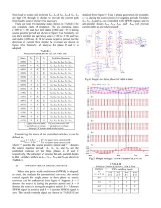
The single-to-three phase ac Matrix Converter circuit is
three legged A, B and C with Six bi-directional switches are
S1 (Sa1- Sa2), S2 (Sc3- Sc4), S3 (Sb1- Sb2), S4 (Sa3- Sa4), S5 (Sc1- Sc2)
and S6 (Sb3- Sb4).The simulation circuit is shown in Figure 6.
Fig.6: Simulation circuit for 1-3 MC with a TM.
The simulation is presented by using SPWM control
technique The Simulation of circuit is simulated with traction
motor parameters by PSIM/MATLAB software packages. The
single phase ac source voltage Vs taken as 1269V and source
frequency fi is 50Hz. When 150 Hz output frequency is
demanded, the simulated results are obtained shows the three
phase output voltages found approximately equal to 2180 V
and three phase output currents are nearly 270 A and also
following 120 degree phase sequence. The input current Ii is
found nearly sinusoidal as expected is shown in Figure 7.
Where, Vab, Vbc and Vca are the line voltages and Va, Vb
and Vc are phase voltages. Ia, Ib and Ic are the output currents
Fig.7: Output waveforms of 1-3MC with a TM.
Fig. 8: Speed-torque-load currents of 1-3 MC with a TM
It can be seen that the Torque-Speed response of the Traction
Motor during motoring operation, the shaft torque Tem and
speed Nis shown in Figure 8 at an accelerating mode.
It is also found that the output voltage parts at the
frequencies | fo− 2 fi | and | fo+ 2 fi | possess big proportions
besides the frequency fo, where, fo is the fundamental
frequency of the output voltage and fi is the frequency of the
source voltage, which implied the influence of the input
supply frequency.
Time
Vab Vbc Vca
Va Vb Vc
Ia Ib Ic
Vs Ii
Speed
Torque
Ia Ib Ic Three phase ac motor currents
Time (s)](https://image.slidesharecdn.com/0c5595ca-49d4-4fae-bbf9-beeb848561e2-150319134151-conversion-gate01/85/1569637039-4-320.jpg)
![Fig. 9: FFT of input current and output voltages of 1-3 MC
At the same time the amplitudes of the output voltages
fluctuate at about 100Hz, the Fast Fourier Transform (FFT)
taken after simulation is shown in Figure 9, which is twice the
source frequency fi. This fluctuating is due to the SPWM
control signals having relation only with the sign of the source
voltage but not with the instantaneous value of the source
voltage. The instantaneous value of the source voltage
influences the output voltage directly. The low voltage ratio is
the weakness of the matrix converter, which should be
improved with some other efficient methods like SVPWM
(space vector PWM), Fuzzy logic, etc.
V. CONCLUSION
The proposed matrix converter topology for single phase to
three phase ac conversion is used for traction drives. This is
analyzed to indicate the operational features of MC with six
bidirectional switches. The operation of this MC with SPWM
is verified with simulation. This simplified control approach is
suitable for general purpose implementation. The three phase
traction motor drives performance indicates the satisfactory
operation of this converter. This 1-3MC is a direct single stage
ac-ac converter topology could be used to retrofit the existing
two stage ac-dc-ac converter with dc link traction drives. This
is also suitable for conversion of single phase transmission
lines into three phase ac lines for Domestic, Industrial and
Agricultural applications at remote places.
REFERENCES
[1] Satya Sahitya Sekhar Nuka.; Dr. R. Saravana Kumar, “Implementation
of Sinusoidal PWM Technique for AC-AC Matrix Converter Using
PSIM” 978-1-4244-7926-9/11/$26.00©2011IEEE.
[2] Ashwin Kumar Sahoo.; Meenakshe,; S. S Dash.; and T. Thyagarajan,
“Analysis and simulation of Matrix Converter Using PSIM.”The 7th
International Conference on Power Electronics -October 22-26, 2007/
EXCO, Daegu, Korea.978-1-4244-1872-5/08 IEEE.
[3] S. I. Kahn, P. D. Ziogas and M. H. Rashid, “A Novel single to three
phase static converter,” IEEE Transactions on Industry Applications,
1989, Vol. 25, No.1, pp. 143-152.
[4] Jianmin Xiao.; Wei Zhang.; Hideki Omori,;Keizo Matsui,“A Novel
Operation Strategy for Single-to Three-Phase Matrix Converter”
Electrical Machines and systems,2009,ICMES-2009/5382800,page 1-
6,Cited by:3
[5] P. Wheeler, J. Rodriguez, J. Clare, Empringham and A. Weinstein.,
"Matrix converters: A Technology Review," IEEE Transactions on
Industrial Electronics, vol. 49, no. 2, April 2002,pp. 276 - 288.
[6] Milan, G; Mohamadian, M.;Dehghan, S.M.; Seifi, E,Yazdian, A.,”A
Novel SPWM strategy for single to three-phase matrix converter.”2nd
PEDSTC-2011,IEEE 10.1109/PEDSTC.2011.5742469,Page(s) 495-500,
[7] A. Zuckerberger, D. Weinstock, A. Alexandrovitz, "Simulation of three-
phase loaded matrix converter," in Proc. on Electric Power
Applications, vol. 143, no. 4, July 1996, pp. 294-300.
Bhimrao S. Gajbhiye is research scholar (B.E., M.Tech.
(Power Electronics and Drives)),since 1994 he is working in
Indian Railway’s Research Designs and Standards Organization
(RDSO), Lucknow, (India) and currently he is working in
electric loco shed, central railways , Ajani (Nagpur, Maharashtra State.); as a
senior section engineer. His main research interests are power electronics,
matrix Converters based electrical drives for Railway traction, industrial,
agricultural, and domestic applications.
Dr. M.V.Aware, Professor,(M. Tech., Ph.D.) in VNIT,
Nagpur(India) in Electrical Engineering Department.
Area of Interest: Power electronics, Electrical machines Drives.
Dr. B S. Umre, Assistant Professor,(M. Tech., Ph. D.) in VNIT,
Nagpur(India) in Electrical Engineering Department.
Area of Interest: Torsional Oscillation, Power System,
Electrical Machines.
Rajesh Patil, B.E, M.Tech. IRSEE-1992 batch of Indian
Railways; presently working as Sr.D.E.E.(Traction distribution)
in Central Railways, Nagpur (India).
Area of Interest: Traction drives
Frequency (kHz)
Ii
Va
Vab
fo](https://image.slidesharecdn.com/0c5595ca-49d4-4fae-bbf9-beeb848561e2-150319134151-conversion-gate01/85/1569637039-5-320.jpg)


