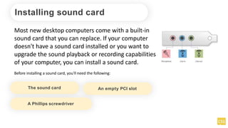
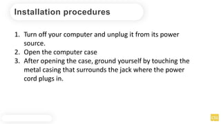
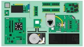
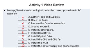
ASSEMBLE COMPUTER
HARDWARE
1.Configure a computer.
2.Set the computer system properly.
3.Learn how to assemble/disassemble
computer.
LEARNING OBJECTIVES
PRE-TEST
Multiple Choice. Write the letter of the correct answer.
1. The first step in preparing the motherboard to go in the case is to __________.
A. Add the CPU B. Add the fan C. Install RAM D. Set the jumpers
2. It is a self-diagnostic program used to perform a simple test of the CPU, RAM, and various
I/O devices.
A. Hub B. Ground Bracelet C. POST D. RAM
3. The main circuit board of a computer is called a _____________.
A. Hub B. Motherboard C. Power Supply D. RAM
4. It is the main secondary storage device of a PC.
A. CD-Rom drive B. Floppy drive C. Hard drive D. Monitor
5. Which is considered NOT a part of a computer's hardware?
A. Keyboard B. Monitor C. RAM D. OS
TOOLS, MATERIALS AND EQUIPMENT
Before you begin building or refitting a computer,
you should have some basic tools:
Phillips-head (cross-shaped)
screwdriver
Needle-nose pliers
Anti-static Wrist Strap
A large level working space
Anti-static bag
TOOLS, MATERIALS AND EQUIPMENT
Some other tools and equipment can come in
handy as well, such as:
Electrical tape
Wire or nylon ties
Flashlight, preferably hands-free
A second, working computer to swap parts, look for tips, ask
for help on-line, download drivers and patches, etc. - very
useful
A can of compressed air - useful when working with older parts
that have collected dust. A better alternative but also expensive,
is a vacuum cleaner designed for cleaning electronics.
Proper preparation is the key to a successful build.
In order to begin a simple work using computer, we
should build first our system unit, and basic
computer configuration setup.
INTRODUCTIONS
installing motherboard component
Unplug the power cord
Prepare anti static pad or bag
Hold edge components
Use anti-static wrist rap
Before you install the motherboard, study the configuration of your chassis to
ensure that the motherboard fits into it.
Take note of the following precautions before installing motherboard
components or changing any motherboard settings.
Getting to know the
internal parts of the
COMPUTER
How are they
assembled?
installing motherboard component
When installing the motherboard, ensure
that you place it into the chassis in the
correct orientation. The edge with external
ports goes to the rear part of the chassis as
indicated in the image below.
H81M-DPLUS
Installing CPU
This motherboard comes with a
surface mount LGA1150 socket
designed for the Intel® 4th
generation Core™ i7 / Core™ i5 /
Core™ i3, Pentium® and Celeron®
processors.
H81M-DPLUS
Safety procedures
Unplug the power cord
Upon purchase of the motherboard, ensure that the PnP cap is on the socket
and the socket contacts are not bent
Use anti-static wrist rap
Keep the cap after installing the
motherboard
1
A
B
2
3
4 C
A
B
5
Install CPU
Install CPU heatsink fan
Apply the Thermal Interface Material
to the CPU heatsink and CPU before
you install the heatsink and fan if
necessary.
Install heatsink fan
1
A
B
B
A
2
3
4
Install system memory
This motherboard comes with two Double Data Rate 3 (DDR3) Dual Inline Memory
Module (DIMM) sockets. A DDR3 module is notched differently from a DDR or DDR2
module. DO NOT install a DDR or DDR2 memory module to the DDR3 slot.
According to Intel® CPU spec, DIMM voltage below 1.65V is recommended to
protect the CPU.
You may install 1GB, 2GB, 4GB, and 8GB unbuffered non-ECC DDR3 DIMMs into the
DIMM sockets.
Install system memory
Unplug the power supply before adding or
removing DIMMs or other system components.
Failure to do so can cause severe damage to
both the motherboard and the components.
1. Press the retaining clips outward to unlock
a DIMM socket.
2. Align a DIMM on the socket such that the
notch on the DIMM matches the DIMM slot
key on the socket.
A DIMM is keyed with a notch so that it fits in only one
direction. DO NOT force a DIMM into
a socket in the wrong direction to avoid damaging the
DIMM.
Install system memory
3. Firmly insert the DIMM into the socket until
the retaining clips snap back in place and the
DIM is properly seated.
Removing system memory
1. Simultaneously press the retaining clips
outward to unlock the DIMM.
Support the DIMM lightly with your fingers
when pressing the retaining clips. The DIMM
might get damaged when it flips out with extra
force.
2. Remove the DIMM from the socket.
2
1
1
DIMMnotch
Activity 1 Video Review
 Arrange/Rewrite in chronological order the correct procedure in PC
assembly
A.Gather Tools and Supplies.
B. Open the Case.
C. Prepare the Case for Assembly.
D.Ground Yourself.
E. Install Motherboard.
F. Install Hard Drive.
G.Install Optical Drive
H.Install the CPU and CPU fan
I. Install the RAM
J. Install the power supply and connect cables
__________
__________
__________
__________
__________
__________
__________
__________
__________
__________
1
2
3
4
5
6
7
8
9
10
Installing expansion cards
Unplug the power cord before adding or removing expansion cards. Failure to do so
may cause you physical injury and damage motherboard components.
To install an expansion card:
1.Before installing the expansion card, read the documentation that came
with it and make the necessary hardware settings for the card.
2.Remove the system unit cover (if your motherboard is already installed in
a chassis).
Installing expansion cards
3.Remove the bracket opposite the slot that you intend to use. Keep the
screw for later use.
4.Align the card connector with the slot and press firmly until the card is
completely
5.seated on the slot.
6.Secure the card to the chassis with the screw you removed earlier.
7.Replace the system cover.
Installing internal connectors
Front panel audio connector (10-1 pin AAFP)
This connector is for a chassis-
mounted front panel audio
I/O module that supports
either HD Audio or legacy
AC`97 audio standard.
Connect one end of the front
panel audio I/O module cable
to this connector.
Installing internal connectors
Digital audio connector (4-1 pin SPDIF_OUT)
This connector is for an
additional Sony/Philips Digital
Interface (S/PDIF) port.
Connect the S/PDIF Out
module cable to this
connector, then install the
module to a slot opening at
the back of the system
chassis.
Installing internal connectors
CPU and chassis fan connectors (4-pin
CPU_FAN, 4-pin CHA_FAN)
Connect the fan cables to the
fan connectors on the
motherboard, ensuring that
the black wire of each cable
matches the ground pin of the
connector.
Do not forget to connect the fan cables to the fan connectors. Insufficient air flow inside the system
may damage the motherboard components. These are not jumpers! Do not place jumper caps on the
fan connectors! The CPU_FAN connector supports a CPU fan of maximum 1A (12 W) fan power.
Installing internal connectors
USB 2.0 connectors (10-1 pin USB910,
USB1112)
These connectors are for USB 2.0
ports. Connect the USB module
cable to any of these connectors,
then install the module to a slot
opening at the back of the system
chassis. These USB connectors
comply with USB 2.0 specifications
and supports up to 480Mbps
connection speed.
Never connect a 1394 cable to the USB connectors.
Doing so will damage the motherboard! The USB 2.0
module is purchased separately.
Installing internal connectors www.facebook.com/itsmeismael
Installing internal connectors
ATX power connectors (24-pin
EATXPWR, 4-pin ATX12V)
These connectors are for ATX
power supply plugs. The
power supply plugs are
designed to fit these
connectors in only one
orientation. Find the proper
orientation and push down
firmly until the connectors
completely fit.
Installing internal connectors
Speaker connector (4-pin SPEAKER)
The 4-pin connector is for
the chassis-mounted system
warning speaker. The
speaker allows you to hear
system beeps and warnings.
Installing internal connectors
Serial ATA 3.0 Gb/s connectors (7-pin SATA3G 1~2 [brown])
These connectors
connect to Serial
ATA3.0 Gb/s hard
disk drives via
Serial ATA 3.0 Gb/s
signal cables.
Installing internal connectors
Serial ATA 6.0Gb/s connectors (7-pin SATA6G_1~2 [yellow])
These connectors
connect to Serial
ATA6.0 Gb/s hard
disk drives via
Serial ATA 6.0 Gb/s
signal cables.
Installing internal connectors
System panel connector (10-1 pin F_PANEL)
This connector supports
several chassis-mounted
functions.
Installing internal connectors
Serial port connector (10-1 pin COM)
This connector is for a
serial (COM) port.
Connect the serial port
module cable to this
connector, then install
the module to a slot
opening at the back of
the system chassis.
Installing internal connectors
USB 3.0 connector (20-1 pin USB3_E12)*
These connectors allow you to connect
a USB 3.0 module for additional USB
3.0 front or rear panel ports. With an
installed USB 3.0 module, you can
enjoy all the benefits of USB 3.0
including faster data transfer speeds of
up to 5Gbps, faster charging time for
USB-chargeable devices, optimized
power efficiency and backward
compatibility with USB 2.0.
*H81M-D PLUS model only.
Installing internal connectors
Onboard LEDs (Standby Power LED)
The motherboard comes with
a standby power LED that
lights up to indicate that the
system is ON, in sleep mode,
or in soft-off mode. This is a
reminder that you should shut
down the system and unplug
the power cable before
removing or plugging in any
motherboard component.
Installing sound card
Most new desktop computers come with a built-in
sound card that you can replace. If your computer
doesn't have a sound card installed or you want to
upgrade the sound playback or recording capabilities
of your computer, you can install a sound card.
Before installing a sound card, you'll need the following:
The sound card An empty PCI slot
A Phillips screwdriver
Installation procedures
1. Turn off your computer and unplug it from its power
source.
2. Open the computer case
3. After opening the case, ground yourself by touching the
metal casing that surrounds the jack where the power
cord plugs in.
To Remove an Existing Sound Card
1. Turn off your computer and unplug it from its power
source.
2. Open the computer case
3. After opening the case, ground yourself by touching the
metal casing that surrounds the jack where the power
cord plugs in.

1.1-4 Assemble Computer Hardware PowerPoint.pptx

  • 1.
  • 2.
    1.Configure a computer. 2.Setthe computer system properly. 3.Learn how to assemble/disassemble computer. LEARNING OBJECTIVES
  • 3.
    PRE-TEST Multiple Choice. Writethe letter of the correct answer. 1. The first step in preparing the motherboard to go in the case is to __________. A. Add the CPU B. Add the fan C. Install RAM D. Set the jumpers 2. It is a self-diagnostic program used to perform a simple test of the CPU, RAM, and various I/O devices. A. Hub B. Ground Bracelet C. POST D. RAM 3. The main circuit board of a computer is called a _____________. A. Hub B. Motherboard C. Power Supply D. RAM 4. It is the main secondary storage device of a PC. A. CD-Rom drive B. Floppy drive C. Hard drive D. Monitor 5. Which is considered NOT a part of a computer's hardware? A. Keyboard B. Monitor C. RAM D. OS
  • 4.
    TOOLS, MATERIALS ANDEQUIPMENT Before you begin building or refitting a computer, you should have some basic tools: Phillips-head (cross-shaped) screwdriver Needle-nose pliers Anti-static Wrist Strap A large level working space Anti-static bag
  • 5.
    TOOLS, MATERIALS ANDEQUIPMENT Some other tools and equipment can come in handy as well, such as: Electrical tape Wire or nylon ties Flashlight, preferably hands-free A second, working computer to swap parts, look for tips, ask for help on-line, download drivers and patches, etc. - very useful A can of compressed air - useful when working with older parts that have collected dust. A better alternative but also expensive, is a vacuum cleaner designed for cleaning electronics. Proper preparation is the key to a successful build.
  • 6.
    In order tobegin a simple work using computer, we should build first our system unit, and basic computer configuration setup. INTRODUCTIONS
  • 7.
    installing motherboard component Unplugthe power cord Prepare anti static pad or bag Hold edge components Use anti-static wrist rap Before you install the motherboard, study the configuration of your chassis to ensure that the motherboard fits into it. Take note of the following precautions before installing motherboard components or changing any motherboard settings.
  • 8.
    Getting to knowthe internal parts of the COMPUTER
  • 10.
  • 12.
    installing motherboard component Wheninstalling the motherboard, ensure that you place it into the chassis in the correct orientation. The edge with external ports goes to the rear part of the chassis as indicated in the image below. H81M-DPLUS
  • 13.
    Installing CPU This motherboardcomes with a surface mount LGA1150 socket designed for the Intel® 4th generation Core™ i7 / Core™ i5 / Core™ i3, Pentium® and Celeron® processors. H81M-DPLUS
  • 14.
    Safety procedures Unplug thepower cord Upon purchase of the motherboard, ensure that the PnP cap is on the socket and the socket contacts are not bent Use anti-static wrist rap Keep the cap after installing the motherboard
  • 15.
  • 16.
    Install CPU heatsinkfan Apply the Thermal Interface Material to the CPU heatsink and CPU before you install the heatsink and fan if necessary.
  • 17.
  • 18.
    Install system memory Thismotherboard comes with two Double Data Rate 3 (DDR3) Dual Inline Memory Module (DIMM) sockets. A DDR3 module is notched differently from a DDR or DDR2 module. DO NOT install a DDR or DDR2 memory module to the DDR3 slot. According to Intel® CPU spec, DIMM voltage below 1.65V is recommended to protect the CPU. You may install 1GB, 2GB, 4GB, and 8GB unbuffered non-ECC DDR3 DIMMs into the DIMM sockets.
  • 19.
    Install system memory Unplugthe power supply before adding or removing DIMMs or other system components. Failure to do so can cause severe damage to both the motherboard and the components. 1. Press the retaining clips outward to unlock a DIMM socket. 2. Align a DIMM on the socket such that the notch on the DIMM matches the DIMM slot key on the socket. A DIMM is keyed with a notch so that it fits in only one direction. DO NOT force a DIMM into a socket in the wrong direction to avoid damaging the DIMM.
  • 20.
    Install system memory 3.Firmly insert the DIMM into the socket until the retaining clips snap back in place and the DIM is properly seated.
  • 21.
    Removing system memory 1.Simultaneously press the retaining clips outward to unlock the DIMM. Support the DIMM lightly with your fingers when pressing the retaining clips. The DIMM might get damaged when it flips out with extra force. 2. Remove the DIMM from the socket. 2 1 1 DIMMnotch
  • 22.
    Activity 1 VideoReview  Arrange/Rewrite in chronological order the correct procedure in PC assembly A.Gather Tools and Supplies. B. Open the Case. C. Prepare the Case for Assembly. D.Ground Yourself. E. Install Motherboard. F. Install Hard Drive. G.Install Optical Drive H.Install the CPU and CPU fan I. Install the RAM J. Install the power supply and connect cables __________ __________ __________ __________ __________ __________ __________ __________ __________ __________
  • 23.
    Activity 1 VideoReview  Arrange/Rewrite in chronological order the correct procedure in PC assembly A.Gather Tools and Supplies. B. Open the Case. C. Prepare the Case for Assembly. D.Ground Yourself. E. Install Motherboard. F. Install Hard Drive. G.Install Optical Drive H.Install the CPU and CPU fan I. Install the RAM J. Install the power supply and connect cables __________ __________ __________ __________ __________ __________ __________ __________ __________ __________ 1 2 3 4 5 6 7 8 9 10
  • 24.
    Installing expansion cards Unplugthe power cord before adding or removing expansion cards. Failure to do so may cause you physical injury and damage motherboard components. To install an expansion card: 1.Before installing the expansion card, read the documentation that came with it and make the necessary hardware settings for the card. 2.Remove the system unit cover (if your motherboard is already installed in a chassis).
  • 25.
    Installing expansion cards 3.Removethe bracket opposite the slot that you intend to use. Keep the screw for later use. 4.Align the card connector with the slot and press firmly until the card is completely 5.seated on the slot. 6.Secure the card to the chassis with the screw you removed earlier. 7.Replace the system cover.
  • 26.
    Installing internal connectors Frontpanel audio connector (10-1 pin AAFP) This connector is for a chassis- mounted front panel audio I/O module that supports either HD Audio or legacy AC`97 audio standard. Connect one end of the front panel audio I/O module cable to this connector.
  • 27.
    Installing internal connectors Digitalaudio connector (4-1 pin SPDIF_OUT) This connector is for an additional Sony/Philips Digital Interface (S/PDIF) port. Connect the S/PDIF Out module cable to this connector, then install the module to a slot opening at the back of the system chassis.
  • 28.
    Installing internal connectors CPUand chassis fan connectors (4-pin CPU_FAN, 4-pin CHA_FAN) Connect the fan cables to the fan connectors on the motherboard, ensuring that the black wire of each cable matches the ground pin of the connector. Do not forget to connect the fan cables to the fan connectors. Insufficient air flow inside the system may damage the motherboard components. These are not jumpers! Do not place jumper caps on the fan connectors! The CPU_FAN connector supports a CPU fan of maximum 1A (12 W) fan power.
  • 29.
    Installing internal connectors USB2.0 connectors (10-1 pin USB910, USB1112) These connectors are for USB 2.0 ports. Connect the USB module cable to any of these connectors, then install the module to a slot opening at the back of the system chassis. These USB connectors comply with USB 2.0 specifications and supports up to 480Mbps connection speed. Never connect a 1394 cable to the USB connectors. Doing so will damage the motherboard! The USB 2.0 module is purchased separately. Installing internal connectors www.facebook.com/itsmeismael
  • 30.
    Installing internal connectors ATXpower connectors (24-pin EATXPWR, 4-pin ATX12V) These connectors are for ATX power supply plugs. The power supply plugs are designed to fit these connectors in only one orientation. Find the proper orientation and push down firmly until the connectors completely fit.
  • 31.
    Installing internal connectors Speakerconnector (4-pin SPEAKER) The 4-pin connector is for the chassis-mounted system warning speaker. The speaker allows you to hear system beeps and warnings.
  • 32.
    Installing internal connectors SerialATA 3.0 Gb/s connectors (7-pin SATA3G 1~2 [brown]) These connectors connect to Serial ATA3.0 Gb/s hard disk drives via Serial ATA 3.0 Gb/s signal cables.
  • 33.
    Installing internal connectors SerialATA 6.0Gb/s connectors (7-pin SATA6G_1~2 [yellow]) These connectors connect to Serial ATA6.0 Gb/s hard disk drives via Serial ATA 6.0 Gb/s signal cables.
  • 34.
    Installing internal connectors Systempanel connector (10-1 pin F_PANEL) This connector supports several chassis-mounted functions.
  • 35.
    Installing internal connectors Serialport connector (10-1 pin COM) This connector is for a serial (COM) port. Connect the serial port module cable to this connector, then install the module to a slot opening at the back of the system chassis.
  • 36.
    Installing internal connectors USB3.0 connector (20-1 pin USB3_E12)* These connectors allow you to connect a USB 3.0 module for additional USB 3.0 front or rear panel ports. With an installed USB 3.0 module, you can enjoy all the benefits of USB 3.0 including faster data transfer speeds of up to 5Gbps, faster charging time for USB-chargeable devices, optimized power efficiency and backward compatibility with USB 2.0. *H81M-D PLUS model only.
  • 37.
    Installing internal connectors OnboardLEDs (Standby Power LED) The motherboard comes with a standby power LED that lights up to indicate that the system is ON, in sleep mode, or in soft-off mode. This is a reminder that you should shut down the system and unplug the power cable before removing or plugging in any motherboard component.
  • 38.
    Installing sound card Mostnew desktop computers come with a built-in sound card that you can replace. If your computer doesn't have a sound card installed or you want to upgrade the sound playback or recording capabilities of your computer, you can install a sound card. Before installing a sound card, you'll need the following: The sound card An empty PCI slot A Phillips screwdriver
  • 39.
    Installation procedures 1. Turnoff your computer and unplug it from its power source. 2. Open the computer case 3. After opening the case, ground yourself by touching the metal casing that surrounds the jack where the power cord plugs in.
  • 40.
    To Remove anExisting Sound Card 1. Turn off your computer and unplug it from its power source. 2. Open the computer case 3. After opening the case, ground yourself by touching the metal casing that surrounds the jack where the power cord plugs in.