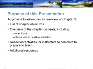
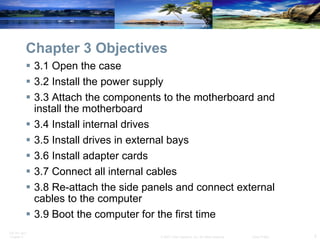
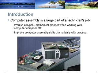
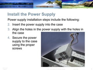
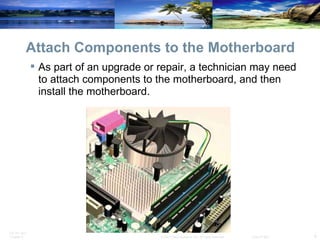
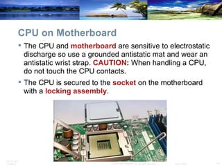
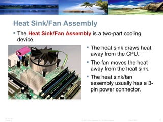
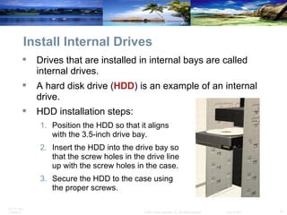
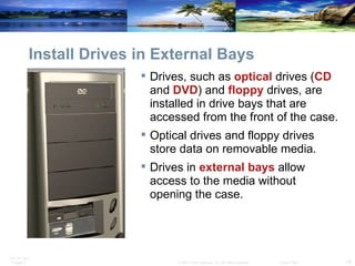
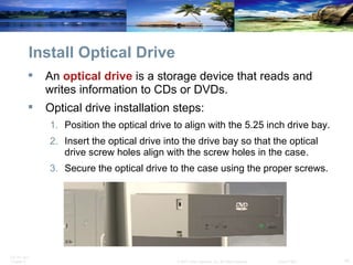
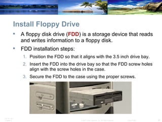
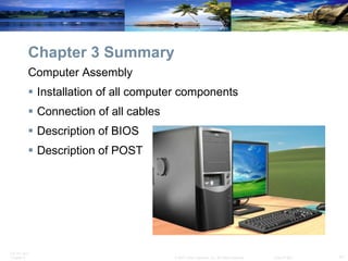
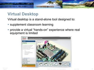
SlideShare a Scribd company logo
1 of 47
Chapter 3:  Computer Assembly IT Essentials: PC Hardware and Software v4.0
Purpose of this Presentation ,[object Object],[object Object],[object Object],[object Object],[object Object],[object Object],To provide to instructors an overview of Chapter 3:
Chapter 3 Objectives ,[object Object],[object Object],[object Object],[object Object],[object Object],[object Object],[object Object],[object Object],[object Object]
Chapter 3 Labs ,[object Object],[object Object],[object Object],[object Object],[object Object],[object Object],[object Object]
Optional Virtual Desktop Activities ,[object Object],[object Object],[object Object],[object Object],[object Object],[object Object],[object Object]
Introduction ,[object Object],[object Object],[object Object]
Open the Case ,[object Object],[object Object],[object Object],[object Object],[object Object],[object Object],[object Object],[object Object],[object Object]
Install the Power Supply ,[object Object],[object Object],[object Object],[object Object]
Attach Components to the Motherboard ,[object Object]
CPU on Motherboard ,[object Object],[object Object]
Thermal Compound ,[object Object],[object Object],[object Object]
Heat Sink/Fan Assembly ,[object Object],[object Object],[object Object],[object Object]
Install CPU and Heat Sink/Fan Assembly ,[object Object],[object Object],[object Object],[object Object],[object Object],[object Object],[object Object],[object Object]
Install RAM ,[object Object],[object Object],[object Object],[object Object],[object Object]
The Motherboard ,[object Object],[object Object],[object Object],[object Object]
Install Motherboard ,[object Object],[object Object],[object Object],[object Object],[object Object]
Install Internal Drives ,[object Object],[object Object],[object Object],[object Object],[object Object],[object Object]
Install Drives in External Bays ,[object Object],[object Object],[object Object]
Install Optical Drive ,[object Object],[object Object],[object Object],[object Object],[object Object]
Install Floppy Drive ,[object Object],[object Object],[object Object],[object Object],[object Object]
Install Adapter Cards ,[object Object],[object Object],[object Object],[object Object],[object Object],[object Object]
Install the Network Interface Card (NIC) ,[object Object],[object Object],[object Object],[object Object],[object Object],[object Object]
Install the Wireless NIC ,[object Object],[object Object],[object Object],[object Object],[object Object],[object Object]
Install the Video Adapter Card ,[object Object],[object Object],[object Object],[object Object],[object Object],[object Object]
Connect Internal Cables ,[object Object],[object Object],[object Object]
Connect Power Cables ,[object Object],[object Object],[object Object],[object Object]
Connect Power Cables ,[object Object],[object Object],[object Object],[object Object],Berg SATA Molex
Power Connector Installation Steps ,[object Object],[object Object],[object Object],[object Object],[object Object]
PATA Cables ,[object Object],[object Object],[object Object],[object Object],[object Object],[object Object]
SATA Cables ,[object Object],[object Object],[object Object]
Floppy Drive Cables ,[object Object],[object Object],[object Object],[object Object]
Install Data Cables ,[object Object],[object Object],[object Object],[object Object],[object Object],[object Object]
Re-attach Panels, Connect External Cables ,[object Object],[object Object]
Re-attach Side Panels ,[object Object],[object Object],[object Object],[object Object]
Connect External Cables ,[object Object],[object Object],[object Object],[object Object],[object Object],[object Object],[object Object]
Connect External Cables ,[object Object],[object Object],[object Object],[object Object],[object Object],[object Object],[object Object],[object Object]
Boot Computer for the First Time ,[object Object],[object Object],[object Object],[object Object]
Identify Beep Codes ,[object Object],[object Object],[object Object],[object Object],[object Object],[object Object]
BIOS Setup ,[object Object],[object Object],[object Object],[object Object],[object Object]
BIOS Setup Program BIOS settings are configured in the BIOS setup program.
Chapter 3 Summary ,[object Object],[object Object],[object Object],[object Object],[object Object]
Virtual Desktop ,[object Object],[object Object],[object Object]
Objectives for Virtual Desktop Activity ,[object Object],[object Object],[object Object]
Discuss Virtual Desktop ,[object Object],[object Object],[object Object],[object Object]
Additional Resources ,[object Object],[object Object],[object Object],[object Object],[object Object],[object Object],[object Object],[object Object],[object Object]
Q and A
 

More Related Content

Viewers also liked (10)

Introduction to HTML5 & CSS3
Introduction to HTML5 & CSS3Introduction to HTML5 & CSS3
Introduction to HTML5 & CSS3
 
Php Ppt
Php PptPhp Ppt
Php Ppt
 
Java script ppt
Java script pptJava script ppt
Java script ppt
 
Basic Wordpress PPT
Basic Wordpress PPT Basic Wordpress PPT
Basic Wordpress PPT
 
HTML CSS Basics
HTML CSS BasicsHTML CSS Basics
HTML CSS Basics
 
JavaScript - An Introduction
JavaScript - An IntroductionJavaScript - An Introduction
JavaScript - An Introduction
 
Php Presentation
Php PresentationPhp Presentation
Php Presentation
 
Php mysql ppt
Php mysql pptPhp mysql ppt
Php mysql ppt
 
jQuery PPT
jQuery PPTjQuery PPT
jQuery PPT
 
Html / CSS Presentation
Html / CSS PresentationHtml / CSS Presentation
Html / CSS Presentation
 

Similar to Dasar komputer chapter3

Computer hardware basic -shashank
Computer hardware basic  -shashankComputer hardware basic  -shashank
Computer hardware basic -shashanktechbed
 
Computer Assembly.pptx
Computer Assembly.pptxComputer Assembly.pptx
Computer Assembly.pptxAndrew_Braza
 
SYSTEM ADMINISTRATION AND MAINTENANCE NOTES PERIYAR UNIVERSITY
SYSTEM ADMINISTRATION AND MAINTENANCE NOTES PERIYAR UNIVERSITYSYSTEM ADMINISTRATION AND MAINTENANCE NOTES PERIYAR UNIVERSITY
SYSTEM ADMINISTRATION AND MAINTENANCE NOTES PERIYAR UNIVERSITYGOKUL SREE
 
Css grade 11 week 4
Css grade 11 week 4Css grade 11 week 4
Css grade 11 week 4Danilo Anos
 
Assemble a desktop pc
Assemble a desktop pcAssemble a desktop pc
Assemble a desktop pcRajat Gupta
 
1.1-4 Assemble Computer Hardware PowerPoint.pptx
1.1-4 Assemble Computer Hardware PowerPoint.pptx1.1-4 Assemble Computer Hardware PowerPoint.pptx
1.1-4 Assemble Computer Hardware PowerPoint.pptxRandyGaray
 
Computer 10 Other Parts of the Internal System Unit
Computer 10 Other Parts of the Internal System UnitComputer 10 Other Parts of the Internal System Unit
Computer 10 Other Parts of the Internal System UnitJessaBejer1
 
pc assembly 1111111pc assembly 1111111- Copy.pptx
pc assembly 1111111pc assembly 1111111- Copy.pptxpc assembly 1111111pc assembly 1111111- Copy.pptx
pc assembly 1111111pc assembly 1111111- Copy.pptxCarloCimacio
 
Assembling a computer
Assembling a computerAssembling a computer
Assembling a computerNeeraj Dhiman
 
Building a computer virtual desktop computer components
Building a computer virtual desktop computer componentsBuilding a computer virtual desktop computer components
Building a computer virtual desktop computer componentsOriginalGSM
 
Assembling and disassembling pc. pdf
Assembling and disassembling pc. pdfAssembling and disassembling pc. pdf
Assembling and disassembling pc. pdfJohnRebenRequinto1
 
Computer Hardware & Software Lab Manual 4
Computer Hardware & Software Lab Manual 4Computer Hardware & Software Lab Manual 4
Computer Hardware & Software Lab Manual 4senayteklay
 

Similar to Dasar komputer chapter3 (20)

Computer hardware basic -shashank
Computer hardware basic  -shashankComputer hardware basic  -shashank
Computer hardware basic -shashank
 
Computer Assembly.pptx
Computer Assembly.pptxComputer Assembly.pptx
Computer Assembly.pptx
 
ASSEMBLY-AND-DISASSEMBLY (1).pptx
ASSEMBLY-AND-DISASSEMBLY (1).pptxASSEMBLY-AND-DISASSEMBLY (1).pptx
ASSEMBLY-AND-DISASSEMBLY (1).pptx
 
ASSEMBLY-AND-DISASSEMBLY.pptx
ASSEMBLY-AND-DISASSEMBLY.pptxASSEMBLY-AND-DISASSEMBLY.pptx
ASSEMBLY-AND-DISASSEMBLY.pptx
 
ASSEMBLY-AND-DISASSEMBLY.pptx
ASSEMBLY-AND-DISASSEMBLY.pptxASSEMBLY-AND-DISASSEMBLY.pptx
ASSEMBLY-AND-DISASSEMBLY.pptx
 
SYSTEM ADMINISTRATION AND MAINTENANCE NOTES PERIYAR UNIVERSITY
SYSTEM ADMINISTRATION AND MAINTENANCE NOTES PERIYAR UNIVERSITYSYSTEM ADMINISTRATION AND MAINTENANCE NOTES PERIYAR UNIVERSITY
SYSTEM ADMINISTRATION AND MAINTENANCE NOTES PERIYAR UNIVERSITY
 
Css grade 11 week 4
Css grade 11 week 4Css grade 11 week 4
Css grade 11 week 4
 
Assemble a desktop pc
Assemble a desktop pcAssemble a desktop pc
Assemble a desktop pc
 
1.1-4 Assemble Computer Hardware PowerPoint.pptx
1.1-4 Assemble Computer Hardware PowerPoint.pptx1.1-4 Assemble Computer Hardware PowerPoint.pptx
1.1-4 Assemble Computer Hardware PowerPoint.pptx
 
BuildingAComputer
BuildingAComputerBuildingAComputer
BuildingAComputer
 
Ite pc v40_chapter3
Ite pc v40_chapter3Ite pc v40_chapter3
Ite pc v40_chapter3
 
Computer 10 Other Parts of the Internal System Unit
Computer 10 Other Parts of the Internal System UnitComputer 10 Other Parts of the Internal System Unit
Computer 10 Other Parts of the Internal System Unit
 
2.3
2.32.3
2.3
 
Assembling the computer
Assembling the computerAssembling the computer
Assembling the computer
 
pc assembly 1111111pc assembly 1111111- Copy.pptx
pc assembly 1111111pc assembly 1111111- Copy.pptxpc assembly 1111111pc assembly 1111111- Copy.pptx
pc assembly 1111111pc assembly 1111111- Copy.pptx
 
Assembling a computer
Assembling a computerAssembling a computer
Assembling a computer
 
ITE7_Chp2.pptx
ITE7_Chp2.pptxITE7_Chp2.pptx
ITE7_Chp2.pptx
 
Building a computer virtual desktop computer components
Building a computer virtual desktop computer componentsBuilding a computer virtual desktop computer components
Building a computer virtual desktop computer components
 
Assembling and disassembling pc. pdf
Assembling and disassembling pc. pdfAssembling and disassembling pc. pdf
Assembling and disassembling pc. pdf
 
Computer Hardware & Software Lab Manual 4
Computer Hardware & Software Lab Manual 4Computer Hardware & Software Lab Manual 4
Computer Hardware & Software Lab Manual 4
 

More from teknik komputer ui (20)

Modul 1
Modul 1Modul 1
Modul 1
 
Modul 5
Modul 5Modul 5
Modul 5
 
Modul 4
Modul 4Modul 4
Modul 4
 
Modul 3
Modul 3Modul 3
Modul 3
 
Modul 1
Modul 1Modul 1
Modul 1
 
Modul 2
Modul 2Modul 2
Modul 2
 
The cisco networking academy net riders indonesia 2010 competition
The cisco networking academy net riders indonesia 2010 competitionThe cisco networking academy net riders indonesia 2010 competition
The cisco networking academy net riders indonesia 2010 competition
 
Rencana Proyek Divisi Komputer.doc
Rencana Proyek Divisi Komputer.docRencana Proyek Divisi Komputer.doc
Rencana Proyek Divisi Komputer.doc
 
Salinan Research Paper
Salinan Research PaperSalinan Research Paper
Salinan Research Paper
 
Chapter_1_Case_Study
Chapter_1_Case_StudyChapter_1_Case_Study
Chapter_1_Case_Study
 
Iins practice questions
Iins practice questionsIins practice questions
Iins practice questions
 
S1 intr ftui
S1 intr ftuiS1 intr ftui
S1 intr ftui
 
Exploration network chapter7
Exploration network chapter7Exploration network chapter7
Exploration network chapter7
 
Exploration network chapter6
Exploration network chapter6Exploration network chapter6
Exploration network chapter6
 
Exploration network chapter5
Exploration network chapter5Exploration network chapter5
Exploration network chapter5
 
Exploration network chapter4
Exploration network chapter4Exploration network chapter4
Exploration network chapter4
 
Exploration network chapter3
Exploration network chapter3Exploration network chapter3
Exploration network chapter3
 
Exploration network chapter2
Exploration network chapter2Exploration network chapter2
Exploration network chapter2
 
Exploration network chapter1
Exploration network chapter1Exploration network chapter1
Exploration network chapter1
 
Exploration network chapter11
Exploration network chapter11Exploration network chapter11
Exploration network chapter11
 

Dasar komputer chapter3

  • 1. Chapter 3: Computer Assembly IT Essentials: PC Hardware and Software v4.0
  • 2.
  • 3.
  • 4.
  • 5.
  • 6.
  • 7.
  • 8.
  • 9.
  • 10.
  • 11.
  • 12.
  • 13.
  • 14.
  • 15.
  • 16.
  • 17.
  • 18.
  • 19.
  • 20.
  • 21.
  • 22.
  • 23.
  • 24.
  • 25.
  • 26.
  • 27.
  • 28.
  • 29.
  • 30.
  • 31.
  • 32.
  • 33.
  • 34.
  • 35.
  • 36.
  • 37.
  • 38.
  • 39.
  • 40. BIOS Setup Program BIOS settings are configured in the BIOS setup program.
  • 41.
  • 42.
  • 43.
  • 44.
  • 45.
  • 47.  

Editor's Notes

  1. Cisco Networking Academy Program IT Essentials: PC Hardware and Software v4.0 Chapter 3: Computer Assembly
  2. Slide 2 – Purpose of this Presentation The purpose of this PowerPoint is to provide to instructors an overview of ITE PC v4.0 Chapter 3, including the following: List of chapter objectives Overview of the chapter contents, including: student labs optional virtual desktop activities Reflection/Activities for instructors to complete to prepare to teach Additional resources
  3. Slide 3 - Chapter 3 Objectives The purpose of this chapter is to provide computer assembly instructions step-by-step. 3.1 Open the case 3.2 Install the power supply 3.3 Attach the components to the motherboard and install the motherboard 3.4 Install internal drives 3.5 Install drives in external bays 3.6 Install adapter cards 3.7 Connect all internal cables 3.8 Re-attach the side panels and connect external cables to the computer 3.9 Boot the computer for the first time
  4. Slide 4 – Chapter 3 Labs There are seven labs included in Chapter 3. These labs are available at the bottom of associated pages of course content. 3.2 Lab: Install the Power Supply (Install a power supply in a computer case.) 3.3.3 Lab: Install the Motherboard (Install a CPU, a heat sink/fan assembly, and a RAM module on the motherboard. Install the motherboard in the computer case.) 3.5.2 Lab: Install the Drives (Install the hard disk drive, the optical drive, and the floppy drive.) 3.6.3 Lab: Install Adapter Cards (Install a NIC, a wireless NIC, and a video adapter card.) 3.7.2 Lab: Install Internal Cables (Install the internal power and data cables in the computer.) 3.8.2 Lab: Complete the Computer Assembly (Install the side panels and the external cables on the computer.) 3.9.2 Lab: Boot the Computer (Boot the computer for the first time, explore the BIOS setup program, and change the boot order sequence.)
  5. Slide 5 – Optional Virtual Desktop Activities There are eight Optional Virtual Desktop activities for students to complete in Chapter 3. Each of these activities focuses on installing desktop components. Note: Instructors might add a reflection/sharing activity for students once they complete each of these activities. These Virtual Desktop activities are optional. System requirements for the virtual desktop include a minimum of 512MB RAM and Windows 2000 or XP operating system. 3.2 Virtual Desktop Power Supply (Complete the power supply layer in the virtual desktop.) 3.3.3 Virtual Desktop Motherboard (Install the motherboard assembly in the virtual desktop motherboard layer.) 3.4 Virtual Desktop Internal Drives (Install the hard drive in the virtual desktop internal drive layer.) 3.5.2 Virtual Desktop External Bay Drives (Install the drive in the virtual desktop external bay drive layer.) 3.6.3 Virtual Desktop Adapter Card (Install the adapter card in the virtual desktop adapter card layer.) 3.7.2 Virtual Desktop Internal Cables (Install the internal cable in the virtual desktop internal cable layer.) 3.8.2 Virtual Desktop External Cables (Install the external cable in the virtual desktop external cable layer.)
  6. Slide 6 – Introduction 3.0 Chapter Introduction Computer assembly is a large part of a technician's job. Work in a logical, methodical manner when working with computer components Improve computer assembly skills dramatically with practice After completing this chapter, students will meet these objectives: Open the case Install the power supply Install the motherboard and attach the components to the motherboard Install the internal drives Install the external drives Install the adapter cards in the appropriate slots Connect all internal cables Re-attach the side panels and connect external cables to the computer Boot the computer for the first time
  7. Slide 7 – Open the case 3.1 Open the case Computer cases are produced in a variety of form factors. Form factors refer to the size and shape of the case. Prepare the workspace before opening the computer case: There should be adequate lighting, good ventilation, and a comfortable room temperature. The workbench or table should be accessible from all sides. Avoid cluttering the surface with tools and computer components. An antistatic mat on the table will help prevent physical and ESD damage to equipment. Small containers can be used to hold screws and other small parts as they are being removed. There are different methods for opening cases. To learn how, consult the user manual or manufacturer's website. Some of the methods include the following: The computer case cover may be removed as one piece. The top and side panels of the case may be removed. The top of the case may need to be removed before the side panels can be removed.
  8. Slide 8 – Install the Power Supply 3.2 Install the power supply A technician may be required to replace or install a power supply. Most power supplies can only fit one way in the computer case. Power supplies have fans that can vibrate and loosen screws that are not secured. Power supply installation steps include the following: Insert the power supply into the case. Align the holes in the power supply with the holes in the case. Secure the power supply to the case using the proper screws. Student Activity: The student course content includes a lab, 3.2 Install the Power Supply. To complete this lab, students will install a power supply in a computer case. Optional Student Activity: The student course content includes the optional activity, 3.2 Virtual Desktop Power Supply. To complete this lab, students will complete the power supply layer in the virtual desktop. System requirements for the virtual desktop include a minimum of 512MB RAM and Windows 2000 or XP operating system.
  9. Slide 9 – Attach Components to the Motherboard 3.3 Attach the components to the motherboard and install the motherboard As part of an upgrade or repair, you may need to install components on the motherboard, and then install the motherboard into the computer case. After completing this section, students will meet these objectives: Install a CPU and a heat sink/fan assembly Install the RAM Install the motherboard
  10. Slide 10 –CPU on Motherboard 3.3.1 Install a CPU and a heat sink/fan assembly The CPU and the heat sink/fan assembly may be installed on the motherboard before the motherboard is placed in the computer case. The CPU and motherboard are sensitive to electrostatic discharge . When handling a CPU or motherboard, make sure that you place them on a grounded antistatic mat . You should also wear an antistatic wrist strap . CAUTION : When handling a CPU, do not touch the CPU contacts. The CPU is secured to the socket on the motherboard with a locking assembly. The CPU sockets today are ZIF sockets. You should be familiar with the locking assembly before attempting to install a CPU into the socket on the motherboard.
  11. Slide 11 – Thermal Compound 3.3.1 Install a CPU and a heat sink/fan assembly Thermal compound helps to keep the CPU cool. It is a substance that increases the transfer of heat from the CPU to the heat sink, where it can be dissipated. To install a used CPU, clean it and the base of the heat sink with isopropyl alcohol to remove the old thermal compound. Follow manufacturer’s recommendations about applying the thermal compound.
  12. Slide 12 – Heat Sink/Fan Assembly 3.3.1 Install a CPU and a heat sink/fan assembly The heat sink/fan assembly is a two-part cooling device. The heat sink draws heat away from the CPU. The fan moves the heat away from the heat sink. The heat sink/fan assembly usually has a 3-pin power connector.
  13. Slide 13 – Install Heat Sink/Fan Assembly 3.3.1 Install a CPU and a heat sink/fan assembly To install the CPU and heat sink/fan assembly: Align the CPU so that the Connection 1 indicator is lined up with Pin 1 on the CPU socket. Place the CPU gently into the socket. Close the CPU load plate and secure it by closing the load lever and moving it under the load lever retention tab. Apply a small amount of thermal compound to the CPU and spread it evenly. Follow the application instructions provided by the manufacturer. Line up the heat sink/fan assembly retainers to the holes on the motherboard. Place the heat sink/fan assembly onto the CPU socket, being careful not to pinch the CPU fan wires Tighten the heat sink/fan assembly retainers to secure the assembly in place Connect the heat sink/fan assembly power cable to the header on the motherboard
  14. Slide 14 – Install RAM 3.3.2 Install the RAM RAM provides temporary data storage for the CPU while the computer is operating. RAM is volatile memory and the contents are lost when the computer is shut down. Typically, adding more RAM will enhance the performance of your computer. RAM should be installed in the motherboard before the motherboard is placed in the computer case. Before you install a stick of RAM, consult the motherboard documentation or website of the manufacturer to ensure that the RAM is compatible with the motherboard. The following are RAM installation steps: Align the notches on the RAM module to the keys in the slot and press down until the side tabs click into place. Make sure that the side tabs have locked the RAM module and visually check for exposed contacts. Repeat these steps for additional RAM modules.
  15. Slide 15 – The Motherboard 3.3.3 Install the motherboard The motherboard is now ready to install in the computer case. Plastic and metal standoffs are used to mount the motherboard and to prevent it from touching the metal portions of the case. You should install only the standoffs that align with the holes in the motherboard. Installing any additional standoffs may prevent the motherboard from being seated properly in the computer case.
  16. Slide 16 – Install the Motherboard 3.3.3 Install the motherboard The following are motherboard installation steps: Install standoffs in the computer case. Align the I/O connectors on the back of the motherboard with the openings in the back of the case. Align the screw holes of the motherboard with the standoffs. Insert all of the motherboard screws. Tighten all of the motherboard screws. Student Activity: The student course content includes a lab, 3.3.3 Install the Motherboard. To complete this lab, students will install a CPU, a heat sink/fan assembly, and a RAM module on the motherboard. Install the motherboard in the computer case. Optional Student Activity: The student course content includes the optional activity, 3.3.3 Virtual Desktop Motherboard. To complete this lab, students will install the motherboard assembly in the virtual desktop motherboard layer. System requirements for the virtual desktop include a minimum of 512MB RAM and Windows 2000 or XP operating system.
  17. Slide 17 – Install Internal Drives 3.4 Install internal drives Drives that are installed in internal bays are called internal drives. A hard disk drive (HDD) is an example of an internal drive. The following are HDD installation steps: Position the HDD so that it aligns with the 3.5-inch drive bay. Insert the HDD into the drive bay so that the screw holes in the drive line up with the screw holes in the case. Secure the HDD to the case using the proper screws. Optional Student Activity: The student course content includes the optional activity, 3.4 Virtual Desktop Internal Drives. To complete this lab, students will install the hard drive in the virtual desktop internal drive layer. System requirements for the virtual desktop include a minimum of 512MB RAM and Windows 2000 or XP operating system.
  18. Slide 18 – Install External Drives 3.5 Install drives in external bays Drives, such as optical drives ( CD and DVD ) and floppy drives, are installed in drive bays that are accessed from the front of the case. Optical drives and floppy drives store data on removable media. Drives in external bays allow access to the media without opening the case. After completing this section, students will meet these objectives: Install the optical drive Install the floppy drive
  19. Slide 19 – Install the Optical Drive 3.5.1 Install the external drive An optical drive is a storage device that reads and writes information to CDs or DVDs. A Molex power connector provides the optical drive with power from the power supply. A PATA cable is used to connect the optical drive to the motherboard. The following are optical drive installation steps: Position the optical drive so that it aligns with the 5.25 inch drive bay. Insert the optical drive into the drive bay so that the optical drive screw holes align with the screw holes in the case. Secure the optical drive to the case using the proper screws.
  20. Slide 20 – Install the Floppy Drive 3.5.2 Install the floppy drive A floppy disk drive (FDD) is a storage device that reads and writes information to a floppy disk. A berg power connector provides the FDD with power from the power supply. A floppy data cable is used to connect the FDD to the motherboard. A floppy disk drive fits into the 3.5 inch bay on the front of the computer case. The following are FDD installation steps: Position the FDD so that it aligns with the 3.5 inch drive bay. Insert the FDD into the drive bay so that the FDD screw holes align with the screw holes in the case. Secure the FDD to the case using the proper screws. Student Activity: The student course content includes a lab, 3.5.2 Install the Drives. To complete this lab, students will install the hard disk drive, the optical drive, and the floppy drive. Optional Student Activity: The student course content includes the optional activity, 3.5.2 Virtual Desktop External Bay Drives. To complete this lab, students will install the drive in the virtual desktop external bay drive layer. System requirements for the virtual desktop include a minimum of 512MB RAM and Windows 2000 or XP operating system.
  21. Slide 21 – Install the Adapter Cards 3.6 Install adapter cards Adapter cards are installed to add functionality to a computer. Adapter cards must be compatible with the expansion slot. This section will focus on the installation of three types of adapter cards. PCIe x1 NIC PCI Wireless NIC PCIe x16 video adapter card After completing this section, students will meet these objectives: Install the NIC Install the wireless NIC Install the video adapter card
  22. Slide 22 – Install the Network Interface Card (NIC) 3.6.1 Install the NIC A NIC enables a computer to connect to a network. NICs use PCI and PCIe expansion slots on the motherboard. The following are NIC installation steps: Align the NIC to the appropriate slot on the motherboard. Press down gently on the NIC until the card is seated. Secure the NIC PC mounting bracket to the case with the appropriate screw.
  23. Slide 23 – Install the Wireless NIC 3.6.2 Install the wireless NIC A wireless NIC enables a computer to connect to a wireless network. Wireless NICs use PCI and PCIe expansion slots on the motherboard. Some wireless NICs are installed externally with a USB connector. You should handle a wireless NIC the same way that you handle an NIC. Make sure that you are using an antistatic wrist strap to prevent damage to the card. Always hold the card by the edges so that you do not damage components or leave moisture on the card. The following are wireless NIC installation steps: Align the wireless NIC to the appropriate expansion slot on the motherboard. Press down gently on the wireless NIC until the card is fully seated. Secure the wireless NIC PC mounting bracket to the case with the appropriate screw.
  24. Slide 24 – Install the Video Adapter Card 3.6.3 Install the video adapter card A video adapter card is the interface between a computer and a display monitor. An upgraded video adapter card can provide better graphic capabilities for games and graphic programs. Video adapter cards use PCI, AGP, and PCIe expansion slots on the motherboard. The following are video adapter card installation steps: Align the video adapter card to the appropriate expansion slot on the motherboard. Press down gently on the video adapter card until the card is fully seated. Secure the video adapter card PC mounting bracket to the case with the appropriate screw. Student Activity: The student course content includes a lab, 3.6.3 Install Adapter Cards. To complete this lab, students will install a NIC, a wireless NIC, and a video adapter card. Optional Student Activity: The student course content includes the optional activity, 3.6.3 Virtual Desktop Adapter Card. To complete this lab, students will install the adapter card in the virtual desktop adapter card layer. System requirements for the virtual desktop include a minimum of 512MB RAM and Windows 2000 or XP operating system.
  25. Slide 25 – Connect Internal Cables 3.7 Connect all internal cables Power cables are used to distribute electricity from the power supply to the motherboard and other components. Data cables transmit data between the motherboard and storage devices, such as hard drives. Additional cables connect the buttons and link lights on the front of the computer case to the motherboard. After completing this section, students will meet these objectives: Connect the power cables Connect the data cables
  26. Slide 26 – Connect Drive Power Cables 3.7.1 Connect the power cables Just like other components, motherboards require power to operate. The Advanced Technology Extended ( ATX ) main power connector will have either 20 or 24 pins. The power supply may also have a 4-pin or 6-pin Auxiliary ( AUX ) power connector that connects to the motherboard. A 20-pin connector will work in a motherboard with a 24-pin socket. The following are motherboard power cable installation steps: Align the 20-pin ATX power connector to the socket on the motherboard. Gently press down on the connector until the clip clicks into place. Align the 4-pin AUX power connector to the socket on the motherboard. Gently press down on the connector until the clip clicks into place.
  27. Slide 27 – Connect Power Cables 3.7.1 Connect the power cables SATA power connectors use a 15-pin connector. SATA power connectors are used to connect to hard disk drives, optical drives, or any devices that have a SATA power socket. Molex Power Connectors are used by hard disk drives and optical drives that do not have SATA power sockets. CAUTION : Do not use a Molex connector and a SATA power connector on the same drive at the same time. 4-pin Berg Power Connector supplies power to a floppy drive.
  28. Slide 28 – Power Connector Installation Steps 3.7.1 Connect the power cables The following are power connector installation steps: Plug the SATA power connector into the HDD. Plug the Molex power connector into the optical drive. Plug the 4-pin Berg power connector into the FDD. Connect the 3-pin fan power connector into the appropriate fan header on the motherboard, according to the motherboard manual. Plug the additional cables from the case into the appropriate connectors according to the motherboard manual.
  29. Slide 29 – PATA Cables 3.7.2 Connect the data cables Drives connect to the motherboard using data cables. Types of data cables are PATA, SATA, and floppy disk. The PATA cable is sometimes called a ribbon cable because it is wide and flat. The PATA cable can have either 40 or 80 conductors. A PATA cable usually has three 40-pin connectors. One connector at the end of the cable connects to the motherboard. The other two connectors connect to drives. If multiple hard drives are installed, the master drive will connect to the end connector. The slave drive will connect to the middle connector. A stripe on the data cable will denote Pin 1. Plug the PATA cable into the drive with the pin 1 indicator on the cable aligned to the pin 1 indicator on the drive connector. The pin 1 indicator on the drive connector is usually closest to the power connector on the drive. Many motherboards have two PATA drive controllers. This provides support for a maximum of four PATA drives.
  30. Slide 30 – SATA Cables 3.7.2 Connect the drive data cables The SATA data cable has a 7-pin connector. One end of the cable is connected to the motherboard. The other end is connected to any drive that has a SATA data connector.
  31. Slide 31 - Connect all Internal Cables 3.7.2 Connect the data cables The floppy drive data cable has a 34-pin connector. Like the PATA data cable, the floppy drive data cable has a stripe to denote the location of pin 1. A floppy drive cable usually has three 34-pin connectors. One connector at the end of the cable connects to the motherboard. The other two connectors connect to drives. If multiple floppy drives are installed, the A: drive will connect to the end connector. The B: drive will connect to the middle connector. Plug the floppy drive data cable into the drive with the pin 1 indicator on the cable aligned to the pin 1 indicator on the drive connector. Motherboards have one floppy drive controller which provides support for a maximum of two floppy drives. NOTE: If pin 1 on the floppy drive data cable is not aligned with pin 1 on the drive connector, the floppy drive will not function. This will not damage the drive, but the drive activity light will display continuously. To fix this problem, turn off the computer and re-connect the data cable so that the pin 1 on the cable and the pin 1 on the connector are aligned. Reboot the computer.
  32. Slide 32 – Install Data Cables 3.7.2 Connect the data cables The following are data cable installation steps: Plug the motherboard end of the PATA cable into the motherboard socket. Plug the connector at the far end of the PATA cable into the optical drive. Plug one end of the SATA cable into the motherboard socket. Plug the other end of the SATA cable into the HDD. Plug the motherboard end of the FDD cable into the motherboard socket. Plug the connector at the far end of the FDD cable into the floppy drive. Student Activity: The student course content includes a lab, 3.7.2 Install Internal Cables. To complete this lab, students will install the internal power and data cables in the computer. Optional Student Activity: The student course content includes the optional activity, 3.7.2 Virtual Desktop Internal Cables. To complete this lab, students will install the internal cable in the virtual desktop internal cable layer. System requirements for the virtual desktop include a minimum of 512MB RAM and Windows 2000 or XP operating system.
  33. Slide 33 – Re-attach Panels, Connect External Cables 3.8 Re-attach the side panels and connect external cables to the computer Now that all the internal components have been installed and connected to the motherboard and power supply, the side panels are re-attached to the computer case. The next step is to connect the cables for all computer peripherals and the power cable. After completing this section, students will meet these objectives: Re-attach the side panels to the case Connect external cables to the computer
  34. Slide 34 – Re-attach Side Panels 3.8.1 Re-attach the side panels to the case Most computer cases have two panels, one on each side. Some computer cases have one three-sided cover that slides down over the case frame. Once the cover is in place, make sure that it is secured at all screw locations. Some computer cases use screws that are inserted with a screwdriver. Other cases have knob-type screws that can be tightened by hand. Refer to the documentation or website of the manufacturer for more information if you are unsure about how to remove or replace the computer case CAUTION : Handle case parts with care. Some computer case covers have sharp or jagged edges.
  35. Slide 35 – Connect External Cables 3.8.2 Connect external cables to the computer After the case panels have been re-attached, connect the external cables to the back of the computer. Here are some common external cable connections: Monitor Keyboard Mouse USB Ethernet Power When attaching cables, ensure that they are connected to the correct locations on the computer. For example, some mouse and keyboard cables use the same type of PS/2 connector. CAUTION: When attaching cables, never force a connection. NOTE : Plug in the power cable after you have connected all other cables.
  36. Slide 36 – Connect External Cables 3.8.2 Connect external cables to the computer The following are external cable installation steps: Attach the monitor cable to the video port. Secure the cable by tightening the screws on the connector. Plug the keyboard cable into the PS/2 keyboard port. Plug the mouse cable into the PS/2 mouse port. Plug the USB cable into a USB port. Plug the network cable into the network port. Connect the wireless antenna to the antenna connector. Plug the power cable into the power supply. Student Activity: The student course content includes a lab, 3.8.2 Complete the Computer Assembly. To complete this lab, students will install the side panels and connect the external cables on the computer. Optional Student Activity: The student course content includes the optional activity, 3.8.2 Virtual Desktop External Cables. To complete this lab, students will install the external cable in the virtual desktop external cable layer. System requirements for the virtual desktop include a minimum of 512MB RAM and Windows 2000 or XP operating system.
  37. Slide 37 – Boot Computer for the First Time 3.9 Boot the computer for the first time When the computer is booted, the basic input/output system (BIOS) will perform a check on all of the internal components. This check is called a power-on self test (POST). The BIOS is a set of instructions stored in a nonvolatile memory chip. Nonvolatile means that the memory retains its contents even if the power is disconnected. A special key or combination of keys on the keyboard is used to enter the BIOS setup program. Most computers use the DEL key. Your computer may use another key or combination of keys. The BIOS setup program displays information about all of the components in the computer. The BIOS setup program is used to configure any settings that the computer components may have. The BIOS setup will allow you to modify settings that control how the computer will boot. After completing this section, students will meet these objectives: Identify beep codes Describe how to enter BIOS and use settings
  38. Slide 38 – Identify Beep Codes 3.9.1 Identify beep codes POST checks to see that all of the hardware in the computer is operating correctly. If a device is malfunctioning, an error or a beep code alerts the technician that there is a problem. Typically, a single beep denotes that the computer is functioning properly. If there is a hardware problem, the computer may emit a series of beeps. Each BIOS manufacturer uses different codes to indicate hardware problems. Consult the motherboard documentation to view beep codes for your computer.
  39. Slide 39 – BIOS Setup 3.9.2 Describe BIOS setup The BIOS contains a setup program used to configure settings for hardware devices. The configuration data is saved to a special memory chip called a complementary metal-oxide semiconductor (CMOS). CMOS is maintained by the battery in the computer. If this battery dies, all BIOS setup configuration data will be lost. Replace the battery and reconfigure the BIOS settings.
  40. Slide 40 – BIOS Setup Program 3.9.2 Describe BIOS setup BIOS settings are configured in the BIOS setup program. To enter this program, you must press the proper key or key sequence during POST. Most computers use the DEL key. Your computer may use another key or combination of keys. Here are some common BIOS setup menu options: Main - System time, date, HDD type, etc. Advanced - Infrared port settings, parallel port settings, etc. Security - Password settings to setup utility Others - Low battery alarm, system beep, etc. Boot - Sets the boot order of the computer Exit - Exits the setup utility Student Activity: The student course content includes a lab, 3.9.2 Boot the Computer. To complete this lab, students will boot the computer for the first time, explore the BIOS setup program, and change the boot order sequence.
  41. Slide 41 – Chapter 3 Summary Some of the important concepts to remember from this module:  Cases come in a variety of sizes and configurations. Many of the components of the computer must match the form factor of the case. The power supply changes AC voltage into DC voltage for the computer components to use. The CPU is installed on the motherboard with a heat sink/fan assembly. RAM is installed in RAM slots found on the motherboard. Adapter cards are installed in PCI and PCIe expansion slots found on the motherboard. Hard disk drives are installed in 3.5 inch drive bays located inside the case. Optical drives are installed in 5.25 inch drive bays that can be accessed from outside the case. Floppy drives are installed in 3.5 inch drive bays that can be accessed from outside the case. Power supply cables are connected to all drives and the motherboard. Internal data cables transfer data to all drives. External cables connect peripheral devices to the computer. Beep codes signify when hardware malfunctions. The BIOS setup program is used to display information about the computer components and allow the user to change system settings.
  42. Slide 44 – Virtual Desktop The Virtual Laptop, Virtual Desktop, and Virtual Printer and Scanner are stand-alone tools designed to supplement classroom learning and provide an interactive “hands-on” experience in learning environments with limited physical equipment. Labs will remain an essential element of the course. System requirements for the virtual desktop include a minimum of 512MB RAM and Windows 2000 or XP operating system. All virtual desktop activities are optional.
  43. Slide 45 – Objectives for Virtual Desktop Activity Learning Objectives for Virtual Desktop instructor lesson Describe the three modes of the Virtual Desktop. Remove and install laptop components in the Virtual Desktop. Participate in discussion of various teaching strategies to use with the Virtual Desktop.
  44. Slide 47 – Discuss Virtual Desktop Discuss questions. Participate in discussion or journal your answers to discussion questions. Do you have any questions now that you have used Virtual Desktop? How do you think your students will react to this tool? What ways do you think you will use Virtual Desktop in ITE PC v4.0? Other comments or thoughts about Virtual Desktop?
  45. Slide 49 – Additional Resources Whatis?com: IT Encyclopedia and Learning Center http://whatis.com TechTarget: The Most Targeted IT Media http://techtarget.com ZDNet: Tech News, Blogs and White Papers for IT Professionals http://www.zdnet.com HowStuffWorks: It's Good to Know http://computer.howstuffworks.com CNET.com http://www.cnet.com PC World http://www.pcworld.com ComputerWorld http://www.computerworld.com WIRED NEWS http://www.wired.com eWEEK.com http://www.eweek.com
  46. Slide 50 – Q and A