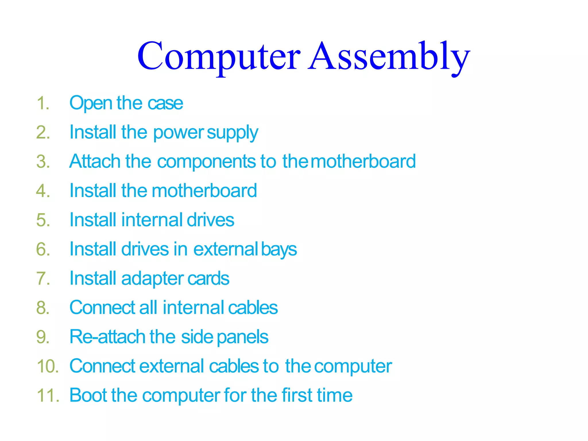
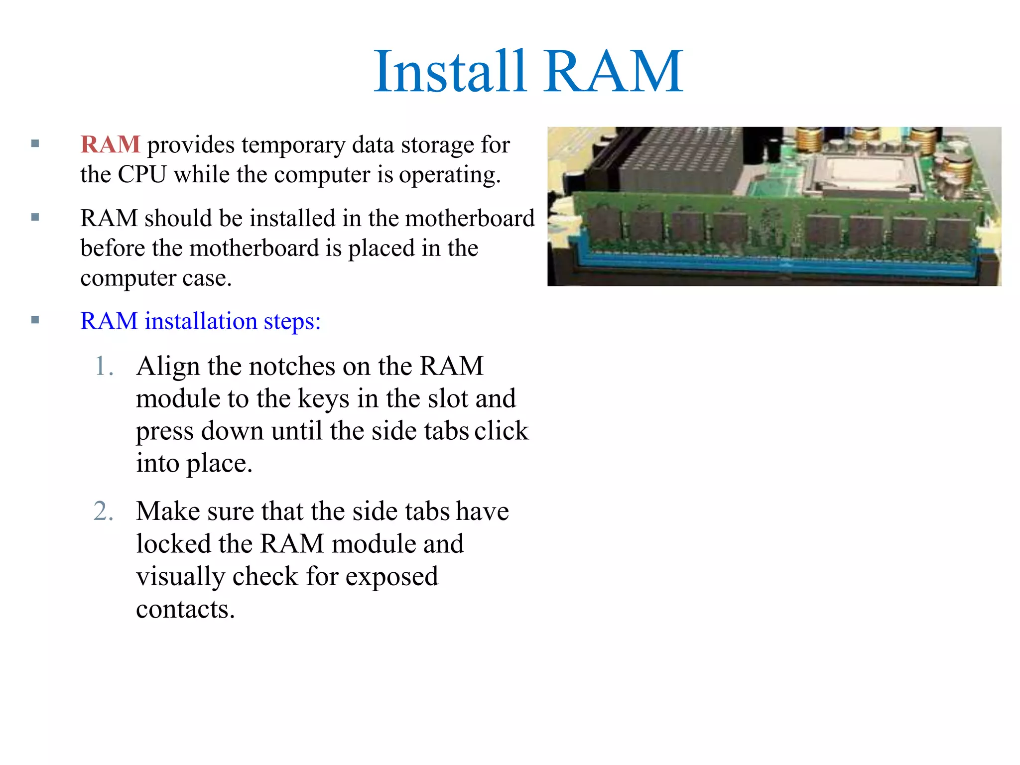
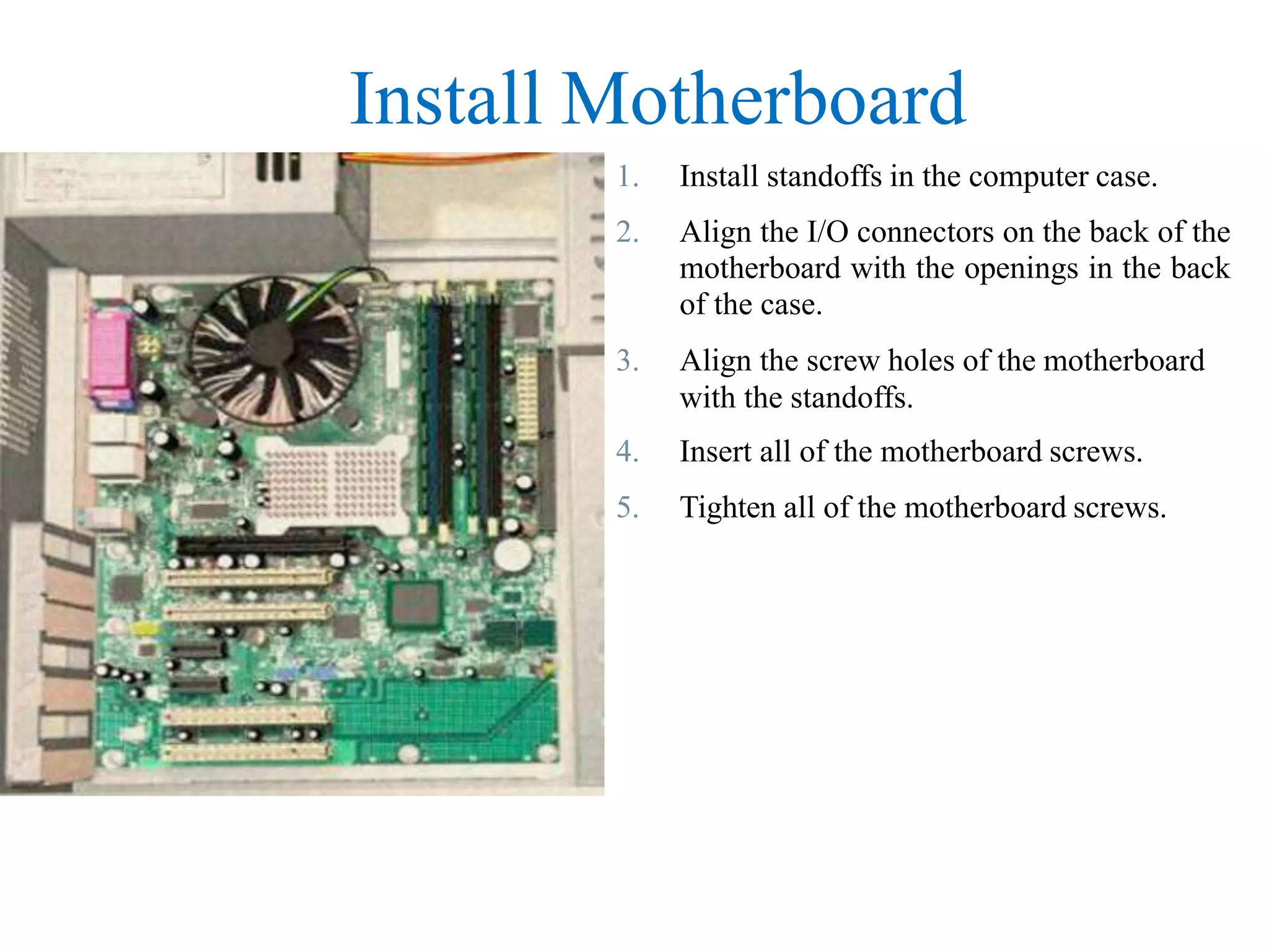
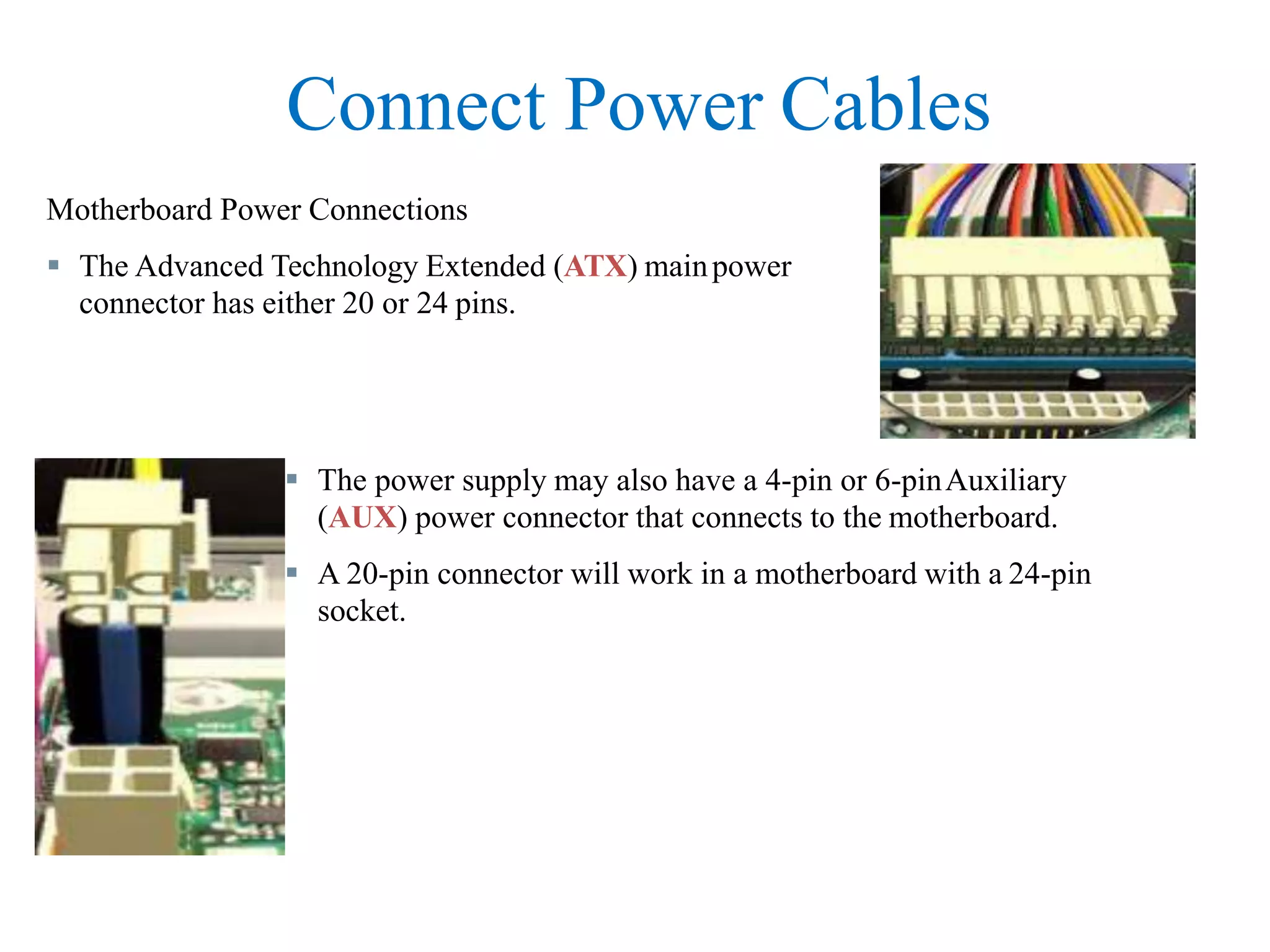
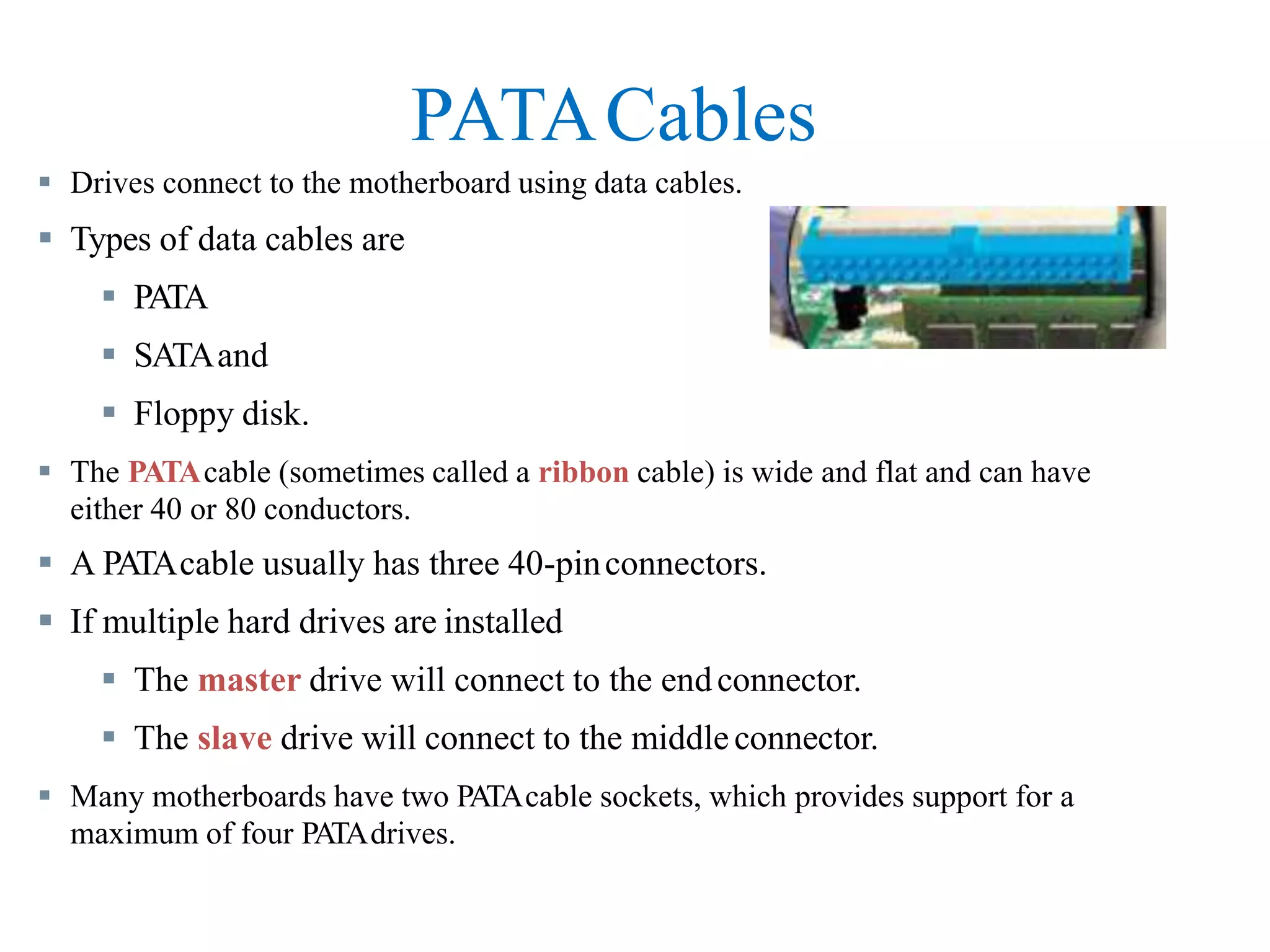
SlideShare a Scribd company logo
Computer Assembly/Disassembly
Computer Assembly
1. Open the case
2. Install the powersupply
3. Attach the components to themotherboard
4. Install the motherboard
5. Install internal drives
6. Install drives in externalbays
7. Install adapter cards
8. Connect all internal cables
9. Re-attach the sidepanels
10. Connect external cables to thecomputer
11. Boot the computer for the first time
Introduction
 Computer assembly is a large
part of a technician's job.
 Work in a logical, methodical
manner when working with
computer components
 Improve computer assembly
skills dramatically with
practice
Open the Case
 Prepare the workspace before opening the computer case:
 Adequate lighting
 Good ventilation
 Comfortable room temperature
 Workbench accessible from all sides
 Avoid cluttering workbench
 An antistatic mat on the table
 Small containers to hold screws and other small parts
 There are different methods for opening cases.
 To learn how, consult the user manual or manufacturer's website.
Install the Power Supply
Power supply installation steps include the
following:
1. Insert the power supply into the case
2. Align the holes in the power supply
with the holes in the case
3. Secure the power supply to the case
using the proper screws
Attach Components to the Motherboard
 As part of an upgrade or repair,
a technician may need
 to attach components to the
motherboard, and then
 install the motherboard.
CPU on Motherboard
 The CPU and motherboard are
sensitive to electrostatic discharge
 use a grounded antistatic mat
and
 wear an antistatic wrist strap.
 CAUTION:
 When handling a CPU, do not
touch the CPU contacts.
 The CPU is secured to the socket
on the motherboard with a locking
assembly.
Thermal Compound
 Thermal compound helps to keep the CPU
cool.
 To install a used CPU,
 clean the base of the heat sink with isopropyl
alcohol to remove the old thermal compound.
 Follow manufacturer’s recommendations
about applying the thermal compound.
Heat Sink/Fan Assembly
The Heat Sink/Fan Assembly is a two-part cooling device.
1. The heat sink draws heat away from
the CPU.
2. The fan moves the heat away from
the heat sink.
 The heat sink/fan assembly usually has
a 3-pin power connector.
Install CPU and Heat Sink/Fan Assembly
1. Align the CPU so that the Connection 1
indicator is lined up with Pin 1 on the CPU
socket.
2. Place the CPU gently into the socket.
3. Close the CPU load plate and secure it by
closing the load lever and moving it under the
load lever retention tab.
4. Apply a small amount of thermal compound to
the CPU and spread it evenly.
5. Line up the heat sink/fan assembly retainers to
the holes on the motherboard.
6. Place the heat sink/fan assembly onto the CPU
socket, being careful not to pinch the CPU fan
wires.
7. Tighten the heat sink/fan assembly retainers to
secure the assembly in place.
8. Connect the heat sink/fan assembly power
cable to the header on the motherboard.
Install RAM
 RAM provides temporary data storage for
the CPU while the computer is operating.
 RAM should be installed in the motherboard
before the motherboard is placed in the
computer case.
 RAM installation steps:
1. Align the notches on the RAM
module to the keys in the slot and
press down until the side tabs click
into place.
2. Make sure that the side tabs have
locked the RAM module and
visually check for exposed
contacts.
The Motherboard
 The motherboard is now ready to install in the computer
case.
 Plastic and metal standoffs are used to mount the
motherboard and to prevent it from touching the metal
portions of the case.
 Install only the standoffs that align with the holes in the
motherboard.
 Installing any additional standoffs may prevent the
motherboard from being seated properly in the computer
case.
Install Motherboard
1. Install standoffs in the computer case.
2. Align the I/O connectors on the back of the
motherboard with the openings in the back
of the case.
3. Align the screw holes of the motherboard
with the standoffs.
4. Insert all of the motherboard screws.
5. Tighten all of the motherboard screws.
Install Internal Drives
 Drives that are installed in internal bays are called internal drives.
 A hard disk drive (HDD) is an example of an internaldrive.
HDD installation steps:
1. Position the HDD so that it aligns with
the 3.5-inch drive bay.
2. Insert the HDD into the drive bay so
that the screw holes in the drive line up
with the screw holes in the case.
3. Secure the HDD to the case using the
proper screws.
Install Drives in External Bays
 Drives, such as optical drives (CD and
DVD) and floppy drives, are installed
in drive bays that are accessed from the
front of the case.
 Optical drives and floppy drives store
data on removable media.
 Drives in external bays allow access
to the media without opening the case.
Install Optical Drive
 Optical drive installation steps:
1. Position the optical drive to align with the 5.25 inch drivebay.
2. Insert the optical drive into the drive bay so that the opticaldrive
screw holes align with the screw holes in the case.
3. Secure the optical drive to the case using the properscrews.
 An optical drive is a storage device that reads and writes information to CDs or
DVDs.
Install Floppy Drive
 A floppy disk drive (FDD) is a storage device that reads and writes informationto
a floppy disk.
 FDD installation steps:
1. Position the FDD so that it aligns with the 3.5 inch drivebay.
2. Insert the FDD into the drive bay so that the FDD screw holes
align with the screw holes in the case.
3. Secure the FDD to the case using the properscrews.
Install Adapter Cards
 Adapter cards are installed to add functionality to a computer.
 Adapter cards must be compatible with the expansion slot.
 Some adapter cards:
• PCIe x1 NIC
• PCI Wireless NIC
• PCIe x16 video adapter card
Install the Network Interface Card (NIC)
 A NIC enables a computer to connect to a network.
 NICs use PCI and PCIe expansion slots on the motherboard.
 NIC installation steps:
1. Align the NIC to the appropriate slot on the
motherboard.
2. Press down gently on the NIC until the card is
seated.
3. Secure the NIC PC mounting bracket to the
case with the appropriate screw.
Install the Wireless NIC
 A wireless NIC enables acomputer
to connect to a wireless network.
 Some wireless NICs are installed
externally with a USB connector.
 Wireless NIC installation steps:
1. Align the wireless NIC to the appropriate expansion slot
on
the motherboard.
2. Press down gently on the wireless NIC until the card is
fully seated.
3. Secure the mounting bracket to the case with the
appropriate
screw.
Install the Video Adapter Card
 A video adapter card is the interface between a computer and a displaymonitor.
 An upgraded video adapter card can provide better graphic capabilities for
games and graphic programs.
 Video adapter card installation steps:
1. Align the video adapter card to
the appropriate expansion sloton
the motherboard.
2. Press down gently on the video
adapter card until the card is fully
seated.
3. Secure the video adapter card
PC mounting bracket to the case
with the appropriate screw.
Connect Internal Cables
 Power cables are used to distribute electricity from the
power supply to the motherboard and other components.
 Data cables transmit data between the motherboard and
storage devices, such as hard drives.
 Additional cables connect the buttons and link lights on
the front of the computer case to the motherboard.
Connect Power Cables
 The power supply may also have a 4-pin or 6-pinAuxiliary
(AUX) power connector that connects to the motherboard.
 A 20-pin connector will work in a motherboard with a 24-pin
socket.
Motherboard Power Connections
 The Advanced Technology Extended (ATX) mainpower
connector has either 20 or 24 pins.
Berg
Connect Power Cables
 SATAPower Connectors use a 15-pin connector to connect to hard disk drives,
optical drives, or any devices that have a SATApower socket.
 Molex Power Connectors are used by hard disk drives and optical drives that do
not have SATApower sockets.
 CAUTION: Do not use a Molex connector and a SATApower connector on the
same drive at the same time.
 4-pin Berg Power Connector supplies power to a floppy drive.
SA
T
A Molex
Power Connector Installation Steps
1. Plug the SATApower connector into the HDD.
2. Plug the Molex power connector into the optical drive.
3. Plug the 4-pin Berg power connector into the FDD.
4. Connect the 3-pin fan power connector into the appropriate fan header on the
motherboard, according to the motherboard manual.
5. Plug the additional cables from the case into the appropriate connectors
according to the motherboard manual.
PATACables
 Drives connect to the motherboard using data cables.
 Types of data cables are
 PATA
 SATAand
 Floppy disk.
 The PATAcable (sometimes called a ribbon cable) is wide and flat and can have
either 40 or 80 conductors.
 A PATAcable usually has three 40-pinconnectors.
 If multiple hard drives are installed
 The master drive will connect to the endconnector.
 The slave drive will connect to the middleconnector.
 Many motherboards have two PATAcable sockets, which provides support for a
maximum of four PATAdrives.
SATACables
 The SATAdata cable has a 7-pin connector.
 One end of the cable is connected to the
motherboard.
 The other end is connected to any drive that
has a SATAdata connector.
Floppy Drive Cables
 The floppy drive data cable has a 34-pin connector and it has a stripe to denote
the location of pin 1.
 One connector at the end of the cable connects to themotherboard.
 The other two connectors connect to drives.
 If multiple floppy drives are installed,
 the A: drive will connect to the endconnector.
 The B: drive will connect to the middle connector.
 Motherboards have one floppy drive controller which provides support for a
maximum of two floppy drives.
Install Data Cables
1. Plug the motherboard end of the PATAcable into the
motherboard socket.
2. Plug the connector at the far end of the PATAcable into the
optical drive.
3. Plug one end of the SATAcable into the motherboard
socket.
4. Plug the other end of the SATAcable into the HDD.
5. Plug the motherboard end of the FDD cable into the
motherboard socket.
6. Plug the connector at the far end of the FDD cable into the
floppy drive.
Re-attach Panels, Connect External Cables
 Now that all the internal components have been installed and
connected to the motherboard and power supply,
 The side panels are re-attached to the computer case.
 The next step is to connect the cables for all computer
peripherals and the power cable.
Re-attach Side Panels
 Most computer cases have two panels, one on each side.
 Once the cover is in place, make sure that it is secured at all
screw locations.
 Refer to the documentation or manufacturer’s website if you
are unsure about how to remove or replace your computer
case.
 CAUTION: Handle case parts
with care. Some computer case
covers have sharp or jagged
edges.
Connect External Cables
 After the case panels have been re-attached, connect the external cables to the back
of the computer.
 External cable connections include:
Monitor
Keyboard Power
Mouse
Ethernet
USB
 CAUTION: When attaching cables, never force a connection.
 NOTE: Plug in the power cable after you have connected all other cables.
Connect External Cables
1. Attach the monitor cable to the video port.
2. Secure the cable by tightening the screws on the
connector.
3. Plug the keyboard cable into the PS/2 keyboard port.
4. Plug the mouse cable into the PS/2 mouse port.
5. Plug the USB cable into a USB port.
6. Plug the network cable into the network port.
7. Connect the wireless antenna to the antenna connector.
8. Plug the power cable into the power supply.
Boot Computer for the First Time
 The BIOS is a set of instructions stored in a nonvolatile memory
chip.
 When the computer is booted, the basic input/output system
(BIOS) will perform a power-on self test (POST) to check on all
of the internal components.
 A special key or combination of keys on the keyboard is used to
enter the BIOS setup program.
 The BIOS setup program displays information about all of the
components in the computer.
Identify Beep Codes
 POST checks to see that all of the hardware in the computer
is operating correctly.
 If a device is malfunctioning, an error or a beep code alerts
the technician that there is a problem.
 Typically, a single beep denotes that the computer is
functioning properly.
 If there is a hardware problem, the computer may emit a
series of beeps.
 Each BIOS manufacturer uses different codes to indicate
hardware problems.
 Consult the motherboard documentation to view beep codes
for your computer.
BIOS Setup
 The BIOS contains a setup program used to configure
settings for hardware devices.
 The configuration data is saved to a special memory chip
called a complementary metal-oxide semiconductor
(CMOS).
 CMOS is maintained by the battery in the computer.
 If this battery dies, all BIOS setup configuration data will be
lost.
 Replace the battery and reconfigure the BIOS settings.
BIOS Configuration
• Technicians use the BIOS information to learn
about installed components:
• CPU – Manufacturer and speed
• RAM - Manufacturer and speed
• Hard Drive - Manufacturer, size, and type
• Optical Drive - manufacturer and type
• Technicians use BIOS to:
• Set Time and Date
• Disable Devices
• Set Boot Order
• Adjust Clock Speed
• Enable Virtualization
BIOS Setup Program
BIOS settings are configured in the BIOS setup program.
Summary
ComputerAssembly
Installation of all computer components
Connection of all cables
Description of BIOS
Description of POST
Computer Disassembly
1. Power off the system
2. Unplug power cables
3. Disconnect external cables from the computer
4. Detach the side panels /open the case
5. Disconnect all internal cables
6. Uninstall adapter cards
7. Uninstall drives from external bays
8. Uninstall internal drives
9. Uninstall the motherboard
10. Uninstall/detach the components from the motherboard
11. Uninstall the power supply
NB. Steps may be vary from computer model to computer model
Lab practice
• Identifying different maintenance tools
• Assembling and Disassembling a computer

More Related Content

Similar to ASSEMBLY-AND-DISASSEMBLY.pptx

Assemble a desktop pc
Assemble a desktop pcAssemble a desktop pc
Assemble a desktop pcRajat Gupta
 
Computer 10 Other Parts of the Internal System Unit
Computer 10 Other Parts of the Internal System UnitComputer 10 Other Parts of the Internal System Unit
Computer 10 Other Parts of the Internal System Unit
JessaBejer1
 
pc assembly 1111111pc assembly 1111111- Copy.pptx
pc assembly 1111111pc assembly 1111111- Copy.pptxpc assembly 1111111pc assembly 1111111- Copy.pptx
pc assembly 1111111pc assembly 1111111- Copy.pptx
CarloCimacio
 
2.3
2.32.3
Assembling the computer
Assembling the computerAssembling the computer
Assembling the computer
Santosh Kulkarni
 
Assembling.pptx
Assembling.pptxAssembling.pptx
Assembling.pptx
GauravSharmaIAHAP
 
Assembling a computer
Assembling a computerAssembling a computer
Assembling a computerNeeraj Dhiman
 
Steps to install motherboard
Steps to install motherboardSteps to install motherboard
Steps to install motherboard
dipaknandankar
 
Install computer system,devices and peripherals
Install computer system,devices and peripheralsInstall computer system,devices and peripherals
Install computer system,devices and peripherals
Raiza Janelle
 
ict 10 4 second q.pptx
ict 10 4 second q.pptxict 10 4 second q.pptx
ict 10 4 second q.pptx
TerrenceRamirez1
 
Assembling and disassembling pc. pdf
Assembling and disassembling pc. pdfAssembling and disassembling pc. pdf
Assembling and disassembling pc. pdf
JohnRebenRequinto1
 
ITE7_Chp2.pptx
ITE7_Chp2.pptxITE7_Chp2.pptx
ITE7_Chp2.pptx
MuhammadYasirKhan36
 
ITE v5.0 - Chapter 3
ITE v5.0 - Chapter 3ITE v5.0 - Chapter 3
ITE v5.0 - Chapter 3
Irsandi Hasan
 
Building a computer in virtual desktop.
Building a computer in virtual desktop.Building a computer in virtual desktop.
Building a computer in virtual desktop.
OriginalGSM
 
Building a computer virtual desktop computer components
Building a computer virtual desktop computer componentsBuilding a computer virtual desktop computer components
Building a computer virtual desktop computer components
OriginalGSM
 
pc-assembly (1).pptx
pc-assembly (1).pptxpc-assembly (1).pptx
pc-assembly (1).pptx
TerrenceRamirez1
 
Pc assembly
Pc assemblyPc assembly
Pc assembly
Mansoor Shar
 
Pc assembly
Pc assemblyPc assembly
Pc assembly
Ruchika Sinha
 

Similar to ASSEMBLY-AND-DISASSEMBLY.pptx (20)

Assemble a desktop pc
Assemble a desktop pcAssemble a desktop pc
Assemble a desktop pc
 
Computer 10 Other Parts of the Internal System Unit
Computer 10 Other Parts of the Internal System UnitComputer 10 Other Parts of the Internal System Unit
Computer 10 Other Parts of the Internal System Unit
 
pc assembly 1111111pc assembly 1111111- Copy.pptx
pc assembly 1111111pc assembly 1111111- Copy.pptxpc assembly 1111111pc assembly 1111111- Copy.pptx
pc assembly 1111111pc assembly 1111111- Copy.pptx
 
2.3
2.32.3
2.3
 
BuildingAComputer
BuildingAComputerBuildingAComputer
BuildingAComputer
 
ITE7_Chp2.pptx
ITE7_Chp2.pptxITE7_Chp2.pptx
ITE7_Chp2.pptx
 
Assembling the computer
Assembling the computerAssembling the computer
Assembling the computer
 
Assembling.pptx
Assembling.pptxAssembling.pptx
Assembling.pptx
 
Assembling a computer
Assembling a computerAssembling a computer
Assembling a computer
 
Steps to install motherboard
Steps to install motherboardSteps to install motherboard
Steps to install motherboard
 
Install computer system,devices and peripherals
Install computer system,devices and peripheralsInstall computer system,devices and peripherals
Install computer system,devices and peripherals
 
ict 10 4 second q.pptx
ict 10 4 second q.pptxict 10 4 second q.pptx
ict 10 4 second q.pptx
 
Assembling and disassembling pc. pdf
Assembling and disassembling pc. pdfAssembling and disassembling pc. pdf
Assembling and disassembling pc. pdf
 
ITE7_Chp2.pptx
ITE7_Chp2.pptxITE7_Chp2.pptx
ITE7_Chp2.pptx
 
ITE v5.0 - Chapter 3
ITE v5.0 - Chapter 3ITE v5.0 - Chapter 3
ITE v5.0 - Chapter 3
 
Building a computer in virtual desktop.
Building a computer in virtual desktop.Building a computer in virtual desktop.
Building a computer in virtual desktop.
 
Building a computer virtual desktop computer components
Building a computer virtual desktop computer componentsBuilding a computer virtual desktop computer components
Building a computer virtual desktop computer components
 
pc-assembly (1).pptx
pc-assembly (1).pptxpc-assembly (1).pptx
pc-assembly (1).pptx
 
Pc assembly
Pc assemblyPc assembly
Pc assembly
 
Pc assembly
Pc assemblyPc assembly
Pc assembly
 

Recently uploaded

JAVIER LASA-EXPERIENCIA digital 1986-2024.pdf
JAVIER LASA-EXPERIENCIA digital 1986-2024.pdfJAVIER LASA-EXPERIENCIA digital 1986-2024.pdf
JAVIER LASA-EXPERIENCIA digital 1986-2024.pdf
Javier Lasa
 
Multi-cluster Kubernetes Networking- Patterns, Projects and Guidelines
Multi-cluster Kubernetes Networking- Patterns, Projects and GuidelinesMulti-cluster Kubernetes Networking- Patterns, Projects and Guidelines
Multi-cluster Kubernetes Networking- Patterns, Projects and Guidelines
Sanjeev Rampal
 
guildmasters guide to ravnica Dungeons & Dragons 5...
guildmasters guide to ravnica Dungeons & Dragons 5...guildmasters guide to ravnica Dungeons & Dragons 5...
guildmasters guide to ravnica Dungeons & Dragons 5...
Rogerio Filho
 
Latest trends in computer networking.pptx
Latest trends in computer networking.pptxLatest trends in computer networking.pptx
Latest trends in computer networking.pptx
JungkooksNonexistent
 
The+Prospects+of+E-Commerce+in+China.pptx
The+Prospects+of+E-Commerce+in+China.pptxThe+Prospects+of+E-Commerce+in+China.pptx
The+Prospects+of+E-Commerce+in+China.pptx
laozhuseo02
 
Internet-Security-Safeguarding-Your-Digital-World (1).pptx
Internet-Security-Safeguarding-Your-Digital-World (1).pptxInternet-Security-Safeguarding-Your-Digital-World (1).pptx
Internet-Security-Safeguarding-Your-Digital-World (1).pptx
VivekSinghShekhawat2
 
This 7-second Brain Wave Ritual Attracts Money To You.!
This 7-second Brain Wave Ritual Attracts Money To You.!This 7-second Brain Wave Ritual Attracts Money To You.!
This 7-second Brain Wave Ritual Attracts Money To You.!
nirahealhty
 
Comptia N+ Standard Networking lesson guide
Comptia N+ Standard Networking lesson guideComptia N+ Standard Networking lesson guide
Comptia N+ Standard Networking lesson guide
GTProductions1
 
1.Wireless Communication System_Wireless communication is a broad term that i...
1.Wireless Communication System_Wireless communication is a broad term that i...1.Wireless Communication System_Wireless communication is a broad term that i...
1.Wireless Communication System_Wireless communication is a broad term that i...
JeyaPerumal1
 
原版仿制(uob毕业证书)英国伯明翰大学毕业证本科学历证书原版一模一样
原版仿制(uob毕业证书)英国伯明翰大学毕业证本科学历证书原版一模一样原版仿制(uob毕业证书)英国伯明翰大学毕业证本科学历证书原版一模一样
原版仿制(uob毕业证书)英国伯明翰大学毕业证本科学历证书原版一模一样
3ipehhoa
 
急速办(bedfordhire毕业证书)英国贝德福特大学毕业证成绩单原版一模一样
急速办(bedfordhire毕业证书)英国贝德福特大学毕业证成绩单原版一模一样急速办(bedfordhire毕业证书)英国贝德福特大学毕业证成绩单原版一模一样
急速办(bedfordhire毕业证书)英国贝德福特大学毕业证成绩单原版一模一样
3ipehhoa
 
BASIC C++ lecture NOTE C++ lecture 3.pptx
BASIC C++ lecture NOTE C++ lecture 3.pptxBASIC C++ lecture NOTE C++ lecture 3.pptx
BASIC C++ lecture NOTE C++ lecture 3.pptx
natyesu
 
APNIC Foundation, presented by Ellisha Heppner at the PNG DNS Forum 2024
APNIC Foundation, presented by Ellisha Heppner at the PNG DNS Forum 2024APNIC Foundation, presented by Ellisha Heppner at the PNG DNS Forum 2024
APNIC Foundation, presented by Ellisha Heppner at the PNG DNS Forum 2024
APNIC
 
一比一原版(CSU毕业证)加利福尼亚州立大学毕业证成绩单专业办理
一比一原版(CSU毕业证)加利福尼亚州立大学毕业证成绩单专业办理一比一原版(CSU毕业证)加利福尼亚州立大学毕业证成绩单专业办理
一比一原版(CSU毕业证)加利福尼亚州立大学毕业证成绩单专业办理
ufdana
 
1比1复刻(bath毕业证书)英国巴斯大学毕业证学位证原版一模一样
1比1复刻(bath毕业证书)英国巴斯大学毕业证学位证原版一模一样1比1复刻(bath毕业证书)英国巴斯大学毕业证学位证原版一模一样
1比1复刻(bath毕业证书)英国巴斯大学毕业证学位证原版一模一样
3ipehhoa
 
How to Use Contact Form 7 Like a Pro.pptx
How to Use Contact Form 7 Like a Pro.pptxHow to Use Contact Form 7 Like a Pro.pptx
How to Use Contact Form 7 Like a Pro.pptx
Gal Baras
 
一比一原版(LBS毕业证)伦敦商学院毕业证成绩单专业办理
一比一原版(LBS毕业证)伦敦商学院毕业证成绩单专业办理一比一原版(LBS毕业证)伦敦商学院毕业证成绩单专业办理
一比一原版(LBS毕业证)伦敦商学院毕业证成绩单专业办理
eutxy
 
一比一原版(SLU毕业证)圣路易斯大学毕业证成绩单专业办理
一比一原版(SLU毕业证)圣路易斯大学毕业证成绩单专业办理一比一原版(SLU毕业证)圣路易斯大学毕业证成绩单专业办理
一比一原版(SLU毕业证)圣路易斯大学毕业证成绩单专业办理
keoku
 
Bridging the Digital Gap Brad Spiegel Macon, GA Initiative.pptx
Bridging the Digital Gap Brad Spiegel Macon, GA Initiative.pptxBridging the Digital Gap Brad Spiegel Macon, GA Initiative.pptx
Bridging the Digital Gap Brad Spiegel Macon, GA Initiative.pptx
Brad Spiegel Macon GA
 
test test test test testtest test testtest test testtest test testtest test ...
test test  test test testtest test testtest test testtest test testtest test ...test test  test test testtest test testtest test testtest test testtest test ...
test test test test testtest test testtest test testtest test testtest test ...
Arif0071
 

Recently uploaded (20)

JAVIER LASA-EXPERIENCIA digital 1986-2024.pdf
JAVIER LASA-EXPERIENCIA digital 1986-2024.pdfJAVIER LASA-EXPERIENCIA digital 1986-2024.pdf
JAVIER LASA-EXPERIENCIA digital 1986-2024.pdf
 
Multi-cluster Kubernetes Networking- Patterns, Projects and Guidelines
Multi-cluster Kubernetes Networking- Patterns, Projects and GuidelinesMulti-cluster Kubernetes Networking- Patterns, Projects and Guidelines
Multi-cluster Kubernetes Networking- Patterns, Projects and Guidelines
 
guildmasters guide to ravnica Dungeons & Dragons 5...
guildmasters guide to ravnica Dungeons & Dragons 5...guildmasters guide to ravnica Dungeons & Dragons 5...
guildmasters guide to ravnica Dungeons & Dragons 5...
 
Latest trends in computer networking.pptx
Latest trends in computer networking.pptxLatest trends in computer networking.pptx
Latest trends in computer networking.pptx
 
The+Prospects+of+E-Commerce+in+China.pptx
The+Prospects+of+E-Commerce+in+China.pptxThe+Prospects+of+E-Commerce+in+China.pptx
The+Prospects+of+E-Commerce+in+China.pptx
 
Internet-Security-Safeguarding-Your-Digital-World (1).pptx
Internet-Security-Safeguarding-Your-Digital-World (1).pptxInternet-Security-Safeguarding-Your-Digital-World (1).pptx
Internet-Security-Safeguarding-Your-Digital-World (1).pptx
 
This 7-second Brain Wave Ritual Attracts Money To You.!
This 7-second Brain Wave Ritual Attracts Money To You.!This 7-second Brain Wave Ritual Attracts Money To You.!
This 7-second Brain Wave Ritual Attracts Money To You.!
 
Comptia N+ Standard Networking lesson guide
Comptia N+ Standard Networking lesson guideComptia N+ Standard Networking lesson guide
Comptia N+ Standard Networking lesson guide
 
1.Wireless Communication System_Wireless communication is a broad term that i...
1.Wireless Communication System_Wireless communication is a broad term that i...1.Wireless Communication System_Wireless communication is a broad term that i...
1.Wireless Communication System_Wireless communication is a broad term that i...
 
原版仿制(uob毕业证书)英国伯明翰大学毕业证本科学历证书原版一模一样
原版仿制(uob毕业证书)英国伯明翰大学毕业证本科学历证书原版一模一样原版仿制(uob毕业证书)英国伯明翰大学毕业证本科学历证书原版一模一样
原版仿制(uob毕业证书)英国伯明翰大学毕业证本科学历证书原版一模一样
 
急速办(bedfordhire毕业证书)英国贝德福特大学毕业证成绩单原版一模一样
急速办(bedfordhire毕业证书)英国贝德福特大学毕业证成绩单原版一模一样急速办(bedfordhire毕业证书)英国贝德福特大学毕业证成绩单原版一模一样
急速办(bedfordhire毕业证书)英国贝德福特大学毕业证成绩单原版一模一样
 
BASIC C++ lecture NOTE C++ lecture 3.pptx
BASIC C++ lecture NOTE C++ lecture 3.pptxBASIC C++ lecture NOTE C++ lecture 3.pptx
BASIC C++ lecture NOTE C++ lecture 3.pptx
 
APNIC Foundation, presented by Ellisha Heppner at the PNG DNS Forum 2024
APNIC Foundation, presented by Ellisha Heppner at the PNG DNS Forum 2024APNIC Foundation, presented by Ellisha Heppner at the PNG DNS Forum 2024
APNIC Foundation, presented by Ellisha Heppner at the PNG DNS Forum 2024
 
一比一原版(CSU毕业证)加利福尼亚州立大学毕业证成绩单专业办理
一比一原版(CSU毕业证)加利福尼亚州立大学毕业证成绩单专业办理一比一原版(CSU毕业证)加利福尼亚州立大学毕业证成绩单专业办理
一比一原版(CSU毕业证)加利福尼亚州立大学毕业证成绩单专业办理
 
1比1复刻(bath毕业证书)英国巴斯大学毕业证学位证原版一模一样
1比1复刻(bath毕业证书)英国巴斯大学毕业证学位证原版一模一样1比1复刻(bath毕业证书)英国巴斯大学毕业证学位证原版一模一样
1比1复刻(bath毕业证书)英国巴斯大学毕业证学位证原版一模一样
 
How to Use Contact Form 7 Like a Pro.pptx
How to Use Contact Form 7 Like a Pro.pptxHow to Use Contact Form 7 Like a Pro.pptx
How to Use Contact Form 7 Like a Pro.pptx
 
一比一原版(LBS毕业证)伦敦商学院毕业证成绩单专业办理
一比一原版(LBS毕业证)伦敦商学院毕业证成绩单专业办理一比一原版(LBS毕业证)伦敦商学院毕业证成绩单专业办理
一比一原版(LBS毕业证)伦敦商学院毕业证成绩单专业办理
 
一比一原版(SLU毕业证)圣路易斯大学毕业证成绩单专业办理
一比一原版(SLU毕业证)圣路易斯大学毕业证成绩单专业办理一比一原版(SLU毕业证)圣路易斯大学毕业证成绩单专业办理
一比一原版(SLU毕业证)圣路易斯大学毕业证成绩单专业办理
 
Bridging the Digital Gap Brad Spiegel Macon, GA Initiative.pptx
Bridging the Digital Gap Brad Spiegel Macon, GA Initiative.pptxBridging the Digital Gap Brad Spiegel Macon, GA Initiative.pptx
Bridging the Digital Gap Brad Spiegel Macon, GA Initiative.pptx
 
test test test test testtest test testtest test testtest test testtest test ...
test test  test test testtest test testtest test testtest test testtest test ...test test  test test testtest test testtest test testtest test testtest test ...
test test test test testtest test testtest test testtest test testtest test ...
 

ASSEMBLY-AND-DISASSEMBLY.pptx

  • 2. Computer Assembly 1. Open the case 2. Install the powersupply 3. Attach the components to themotherboard 4. Install the motherboard 5. Install internal drives 6. Install drives in externalbays 7. Install adapter cards 8. Connect all internal cables 9. Re-attach the sidepanels 10. Connect external cables to thecomputer 11. Boot the computer for the first time
  • 3. Introduction  Computer assembly is a large part of a technician's job.  Work in a logical, methodical manner when working with computer components  Improve computer assembly skills dramatically with practice
  • 4. Open the Case  Prepare the workspace before opening the computer case:  Adequate lighting  Good ventilation  Comfortable room temperature  Workbench accessible from all sides  Avoid cluttering workbench  An antistatic mat on the table  Small containers to hold screws and other small parts  There are different methods for opening cases.  To learn how, consult the user manual or manufacturer's website.
  • 5. Install the Power Supply Power supply installation steps include the following: 1. Insert the power supply into the case 2. Align the holes in the power supply with the holes in the case 3. Secure the power supply to the case using the proper screws
  • 6. Attach Components to the Motherboard  As part of an upgrade or repair, a technician may need  to attach components to the motherboard, and then  install the motherboard.
  • 7. CPU on Motherboard  The CPU and motherboard are sensitive to electrostatic discharge  use a grounded antistatic mat and  wear an antistatic wrist strap.  CAUTION:  When handling a CPU, do not touch the CPU contacts.  The CPU is secured to the socket on the motherboard with a locking assembly.
  • 8. Thermal Compound  Thermal compound helps to keep the CPU cool.  To install a used CPU,  clean the base of the heat sink with isopropyl alcohol to remove the old thermal compound.  Follow manufacturer’s recommendations about applying the thermal compound.
  • 9. Heat Sink/Fan Assembly The Heat Sink/Fan Assembly is a two-part cooling device. 1. The heat sink draws heat away from the CPU. 2. The fan moves the heat away from the heat sink.  The heat sink/fan assembly usually has a 3-pin power connector.
  • 10. Install CPU and Heat Sink/Fan Assembly 1. Align the CPU so that the Connection 1 indicator is lined up with Pin 1 on the CPU socket. 2. Place the CPU gently into the socket. 3. Close the CPU load plate and secure it by closing the load lever and moving it under the load lever retention tab. 4. Apply a small amount of thermal compound to the CPU and spread it evenly. 5. Line up the heat sink/fan assembly retainers to the holes on the motherboard. 6. Place the heat sink/fan assembly onto the CPU socket, being careful not to pinch the CPU fan wires. 7. Tighten the heat sink/fan assembly retainers to secure the assembly in place. 8. Connect the heat sink/fan assembly power cable to the header on the motherboard.
  • 11. Install RAM  RAM provides temporary data storage for the CPU while the computer is operating.  RAM should be installed in the motherboard before the motherboard is placed in the computer case.  RAM installation steps: 1. Align the notches on the RAM module to the keys in the slot and press down until the side tabs click into place. 2. Make sure that the side tabs have locked the RAM module and visually check for exposed contacts.
  • 12. The Motherboard  The motherboard is now ready to install in the computer case.  Plastic and metal standoffs are used to mount the motherboard and to prevent it from touching the metal portions of the case.  Install only the standoffs that align with the holes in the motherboard.  Installing any additional standoffs may prevent the motherboard from being seated properly in the computer case.
  • 13. Install Motherboard 1. Install standoffs in the computer case. 2. Align the I/O connectors on the back of the motherboard with the openings in the back of the case. 3. Align the screw holes of the motherboard with the standoffs. 4. Insert all of the motherboard screws. 5. Tighten all of the motherboard screws.
  • 14. Install Internal Drives  Drives that are installed in internal bays are called internal drives.  A hard disk drive (HDD) is an example of an internaldrive. HDD installation steps: 1. Position the HDD so that it aligns with the 3.5-inch drive bay. 2. Insert the HDD into the drive bay so that the screw holes in the drive line up with the screw holes in the case. 3. Secure the HDD to the case using the proper screws.
  • 15. Install Drives in External Bays  Drives, such as optical drives (CD and DVD) and floppy drives, are installed in drive bays that are accessed from the front of the case.  Optical drives and floppy drives store data on removable media.  Drives in external bays allow access to the media without opening the case.
  • 16. Install Optical Drive  Optical drive installation steps: 1. Position the optical drive to align with the 5.25 inch drivebay. 2. Insert the optical drive into the drive bay so that the opticaldrive screw holes align with the screw holes in the case. 3. Secure the optical drive to the case using the properscrews.  An optical drive is a storage device that reads and writes information to CDs or DVDs.
  • 17. Install Floppy Drive  A floppy disk drive (FDD) is a storage device that reads and writes informationto a floppy disk.  FDD installation steps: 1. Position the FDD so that it aligns with the 3.5 inch drivebay. 2. Insert the FDD into the drive bay so that the FDD screw holes align with the screw holes in the case. 3. Secure the FDD to the case using the properscrews.
  • 18. Install Adapter Cards  Adapter cards are installed to add functionality to a computer.  Adapter cards must be compatible with the expansion slot.  Some adapter cards: • PCIe x1 NIC • PCI Wireless NIC • PCIe x16 video adapter card
  • 19. Install the Network Interface Card (NIC)  A NIC enables a computer to connect to a network.  NICs use PCI and PCIe expansion slots on the motherboard.  NIC installation steps: 1. Align the NIC to the appropriate slot on the motherboard. 2. Press down gently on the NIC until the card is seated. 3. Secure the NIC PC mounting bracket to the case with the appropriate screw.
  • 20. Install the Wireless NIC  A wireless NIC enables acomputer to connect to a wireless network.  Some wireless NICs are installed externally with a USB connector.  Wireless NIC installation steps: 1. Align the wireless NIC to the appropriate expansion slot on the motherboard. 2. Press down gently on the wireless NIC until the card is fully seated. 3. Secure the mounting bracket to the case with the appropriate screw.
  • 21. Install the Video Adapter Card  A video adapter card is the interface between a computer and a displaymonitor.  An upgraded video adapter card can provide better graphic capabilities for games and graphic programs.  Video adapter card installation steps: 1. Align the video adapter card to the appropriate expansion sloton the motherboard. 2. Press down gently on the video adapter card until the card is fully seated. 3. Secure the video adapter card PC mounting bracket to the case with the appropriate screw.
  • 22. Connect Internal Cables  Power cables are used to distribute electricity from the power supply to the motherboard and other components.  Data cables transmit data between the motherboard and storage devices, such as hard drives.  Additional cables connect the buttons and link lights on the front of the computer case to the motherboard.
  • 23. Connect Power Cables  The power supply may also have a 4-pin or 6-pinAuxiliary (AUX) power connector that connects to the motherboard.  A 20-pin connector will work in a motherboard with a 24-pin socket. Motherboard Power Connections  The Advanced Technology Extended (ATX) mainpower connector has either 20 or 24 pins.
  • 24. Berg Connect Power Cables  SATAPower Connectors use a 15-pin connector to connect to hard disk drives, optical drives, or any devices that have a SATApower socket.  Molex Power Connectors are used by hard disk drives and optical drives that do not have SATApower sockets.  CAUTION: Do not use a Molex connector and a SATApower connector on the same drive at the same time.  4-pin Berg Power Connector supplies power to a floppy drive. SA T A Molex
  • 25. Power Connector Installation Steps 1. Plug the SATApower connector into the HDD. 2. Plug the Molex power connector into the optical drive. 3. Plug the 4-pin Berg power connector into the FDD. 4. Connect the 3-pin fan power connector into the appropriate fan header on the motherboard, according to the motherboard manual. 5. Plug the additional cables from the case into the appropriate connectors according to the motherboard manual.
  • 26. PATACables  Drives connect to the motherboard using data cables.  Types of data cables are  PATA  SATAand  Floppy disk.  The PATAcable (sometimes called a ribbon cable) is wide and flat and can have either 40 or 80 conductors.  A PATAcable usually has three 40-pinconnectors.  If multiple hard drives are installed  The master drive will connect to the endconnector.  The slave drive will connect to the middleconnector.  Many motherboards have two PATAcable sockets, which provides support for a maximum of four PATAdrives.
  • 27. SATACables  The SATAdata cable has a 7-pin connector.  One end of the cable is connected to the motherboard.  The other end is connected to any drive that has a SATAdata connector.
  • 28. Floppy Drive Cables  The floppy drive data cable has a 34-pin connector and it has a stripe to denote the location of pin 1.  One connector at the end of the cable connects to themotherboard.  The other two connectors connect to drives.  If multiple floppy drives are installed,  the A: drive will connect to the endconnector.  The B: drive will connect to the middle connector.  Motherboards have one floppy drive controller which provides support for a maximum of two floppy drives.
  • 29. Install Data Cables 1. Plug the motherboard end of the PATAcable into the motherboard socket. 2. Plug the connector at the far end of the PATAcable into the optical drive. 3. Plug one end of the SATAcable into the motherboard socket. 4. Plug the other end of the SATAcable into the HDD. 5. Plug the motherboard end of the FDD cable into the motherboard socket. 6. Plug the connector at the far end of the FDD cable into the floppy drive.
  • 30. Re-attach Panels, Connect External Cables  Now that all the internal components have been installed and connected to the motherboard and power supply,  The side panels are re-attached to the computer case.  The next step is to connect the cables for all computer peripherals and the power cable.
  • 31. Re-attach Side Panels  Most computer cases have two panels, one on each side.  Once the cover is in place, make sure that it is secured at all screw locations.  Refer to the documentation or manufacturer’s website if you are unsure about how to remove or replace your computer case.  CAUTION: Handle case parts with care. Some computer case covers have sharp or jagged edges.
  • 32. Connect External Cables  After the case panels have been re-attached, connect the external cables to the back of the computer.  External cable connections include: Monitor Keyboard Power Mouse Ethernet USB  CAUTION: When attaching cables, never force a connection.  NOTE: Plug in the power cable after you have connected all other cables.
  • 33. Connect External Cables 1. Attach the monitor cable to the video port. 2. Secure the cable by tightening the screws on the connector. 3. Plug the keyboard cable into the PS/2 keyboard port. 4. Plug the mouse cable into the PS/2 mouse port. 5. Plug the USB cable into a USB port. 6. Plug the network cable into the network port. 7. Connect the wireless antenna to the antenna connector. 8. Plug the power cable into the power supply.
  • 34. Boot Computer for the First Time  The BIOS is a set of instructions stored in a nonvolatile memory chip.  When the computer is booted, the basic input/output system (BIOS) will perform a power-on self test (POST) to check on all of the internal components.  A special key or combination of keys on the keyboard is used to enter the BIOS setup program.  The BIOS setup program displays information about all of the components in the computer.
  • 35. Identify Beep Codes  POST checks to see that all of the hardware in the computer is operating correctly.  If a device is malfunctioning, an error or a beep code alerts the technician that there is a problem.  Typically, a single beep denotes that the computer is functioning properly.  If there is a hardware problem, the computer may emit a series of beeps.  Each BIOS manufacturer uses different codes to indicate hardware problems.  Consult the motherboard documentation to view beep codes for your computer.
  • 36. BIOS Setup  The BIOS contains a setup program used to configure settings for hardware devices.  The configuration data is saved to a special memory chip called a complementary metal-oxide semiconductor (CMOS).  CMOS is maintained by the battery in the computer.  If this battery dies, all BIOS setup configuration data will be lost.  Replace the battery and reconfigure the BIOS settings.
  • 37. BIOS Configuration • Technicians use the BIOS information to learn about installed components: • CPU – Manufacturer and speed • RAM - Manufacturer and speed • Hard Drive - Manufacturer, size, and type • Optical Drive - manufacturer and type • Technicians use BIOS to: • Set Time and Date • Disable Devices • Set Boot Order • Adjust Clock Speed • Enable Virtualization
  • 38. BIOS Setup Program BIOS settings are configured in the BIOS setup program.
  • 39. Summary ComputerAssembly Installation of all computer components Connection of all cables Description of BIOS Description of POST
  • 40. Computer Disassembly 1. Power off the system 2. Unplug power cables 3. Disconnect external cables from the computer 4. Detach the side panels /open the case 5. Disconnect all internal cables 6. Uninstall adapter cards 7. Uninstall drives from external bays 8. Uninstall internal drives 9. Uninstall the motherboard 10. Uninstall/detach the components from the motherboard 11. Uninstall the power supply NB. Steps may be vary from computer model to computer model
  • 41. Lab practice • Identifying different maintenance tools • Assembling and Disassembling a computer