Downloaded 60 times


![PROCESSING UNITS
It comprises of Raspberry pi which is a processor on chip. The processing unit acts like an intermediate between the sensors and
cloud. All the sensors are wirelessly connected to the processing unit. A single raspberry pi unit comprises of 26 GPIO pins i.e. 26
different sensors can be connected to it. However we can increase this number by attaching a multiplexer (MUX) to it. It is
essential that the ground of raspberry pi and sensors must be connected in order to transfer data using the GPIO pins. There is a
python script running on the chip that checks the status of various GPIO pins and updates this information onto the cloud. Data
collected from various sensors is sent to the raspberry pi through the esp8266 chip. The raspberry pi then transmits this data to
the IBM MQTT Server through MQTT protocol over a channel. MQTT[15] (Message Queue Telemetry Transport) Protocol is a
publish-subscribe based "light weight" messaging protocol that is used on top of the TCP/IP protocol. It is designed to establish
connections across remote locations where limited amount of data needs to be transferred or in cases of low bandwidth
availability.](https://image.slidesharecdn.com/smartparkingsystem-181107153030/75/Smart-parking-system-using-IOT-10-2048.jpg)
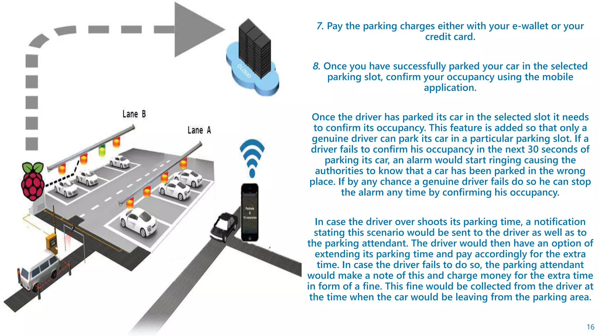


This document presents an IoT-based smart parking system that aims to improve urban parking facilities by integrating cloud technology. It outlines the hardware and software requirements, including sensors, processing units like Raspberry Pi, and a mobile application for user interaction. The system offers real-time information on parking slot availability, allows users to book slots, and automates counting of occupied and available spaces to enhance the overall parking experience.


![Coded Agents – with UiPath SDK + LangGraph [Virtual Hands-on Workshop]](https://cdn.slidesharecdn.com/ss_thumbnails/codedagentsdeck-251215155422-5497c599-thumbnail.jpg?width=640&height=640&fit=bounds)


