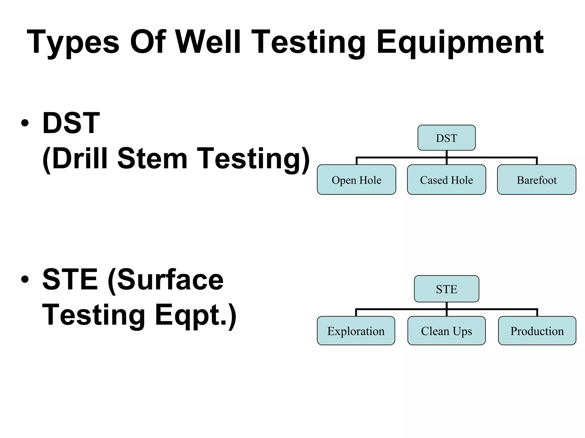
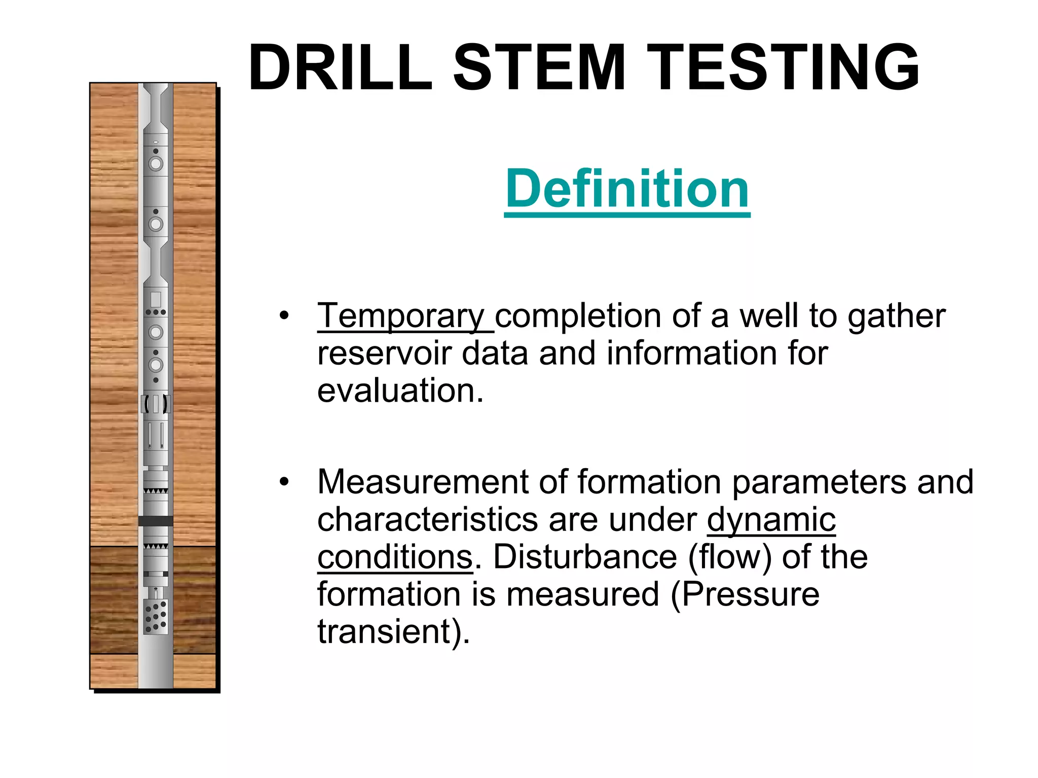
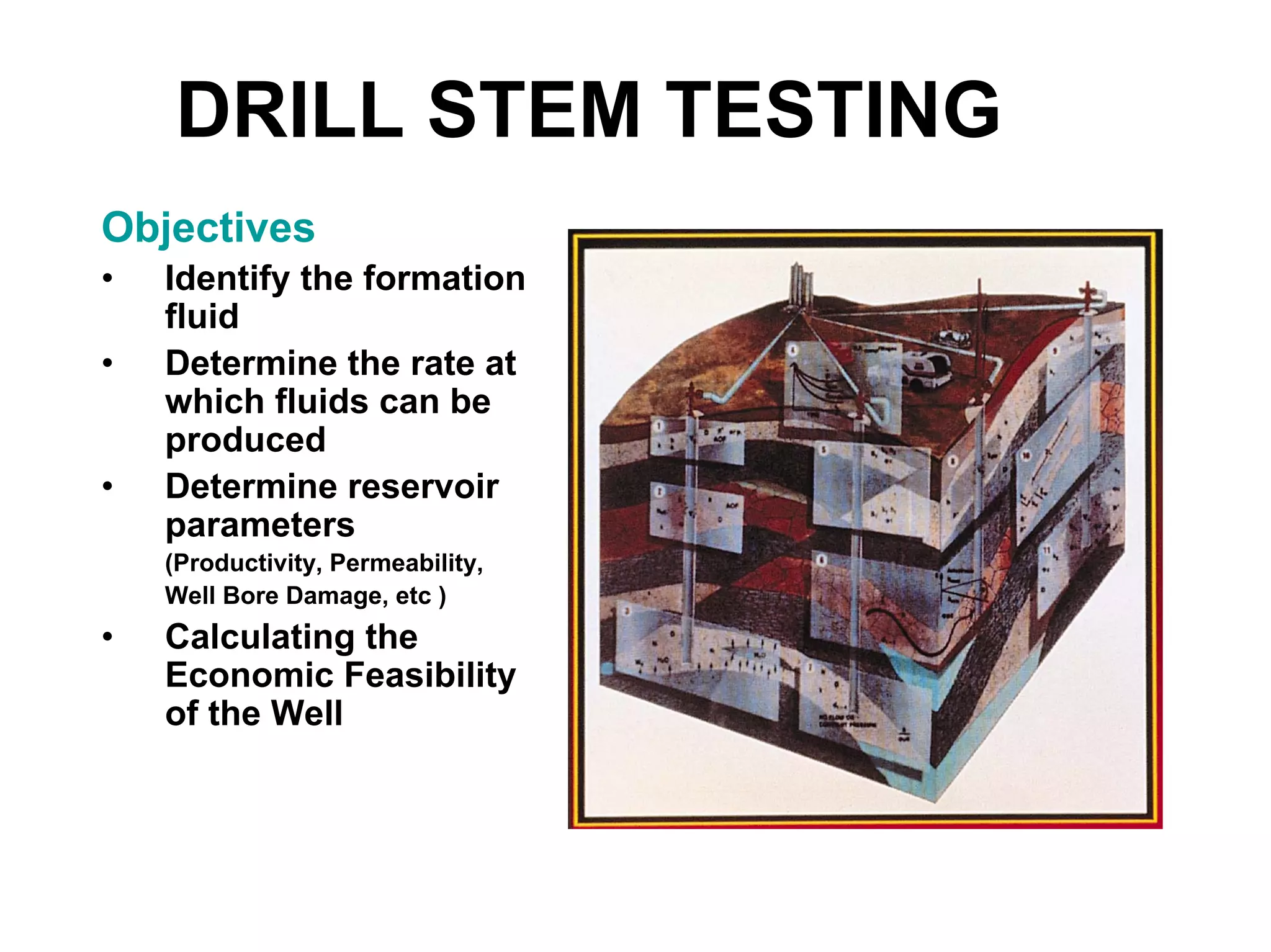
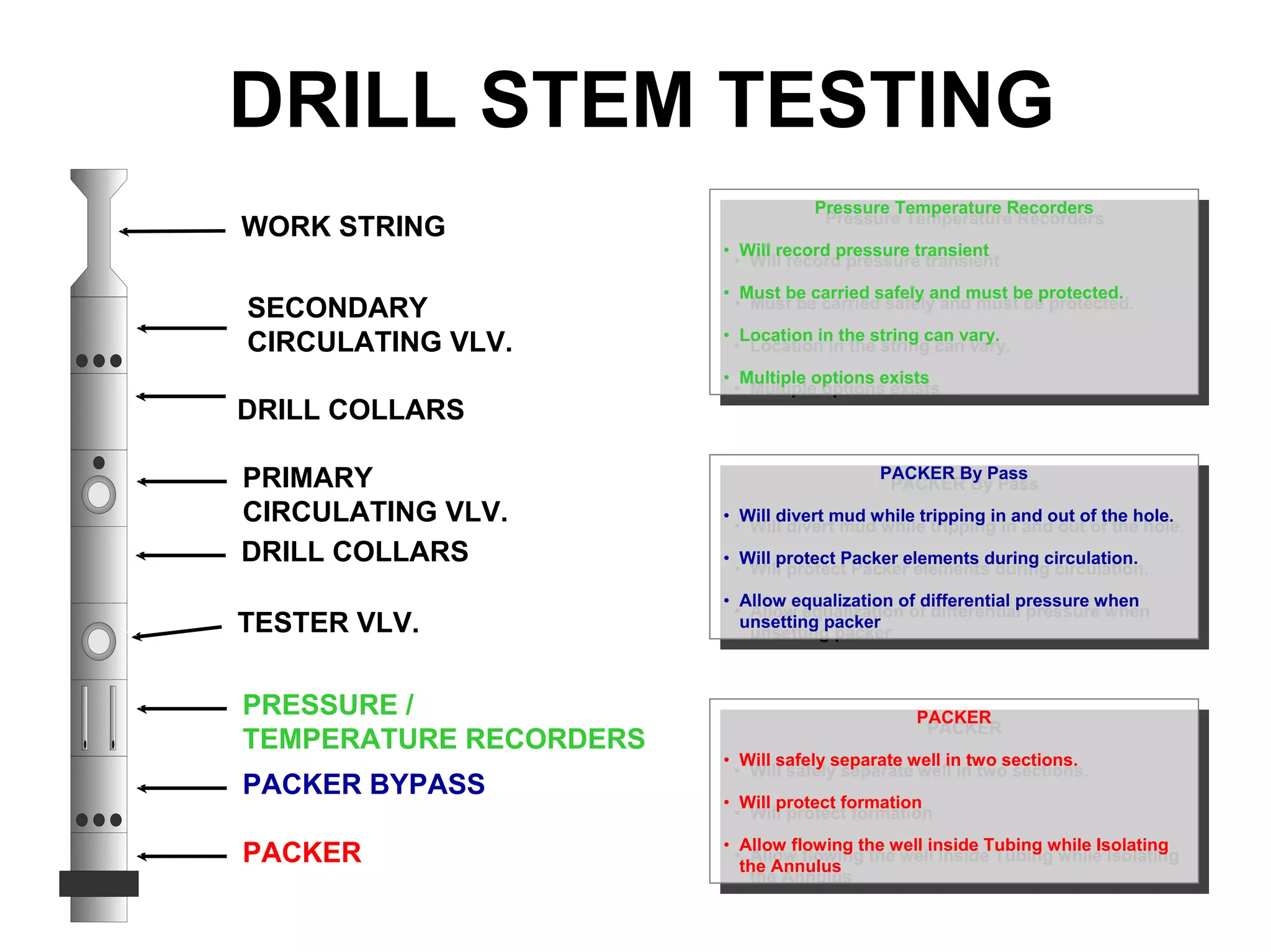
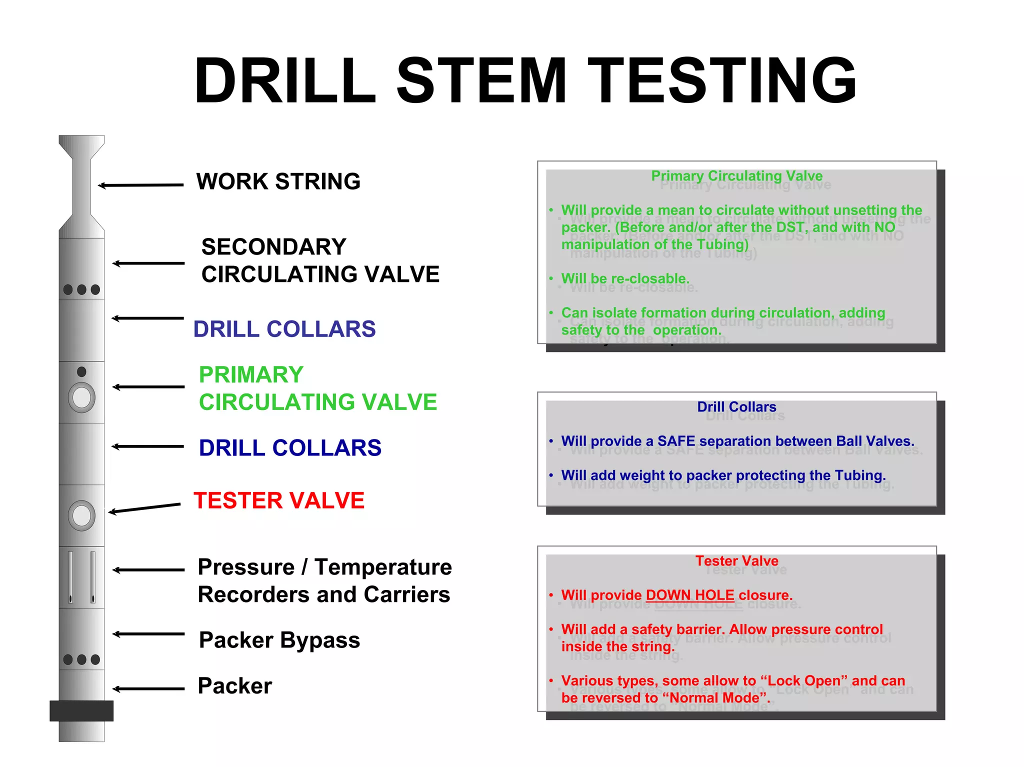
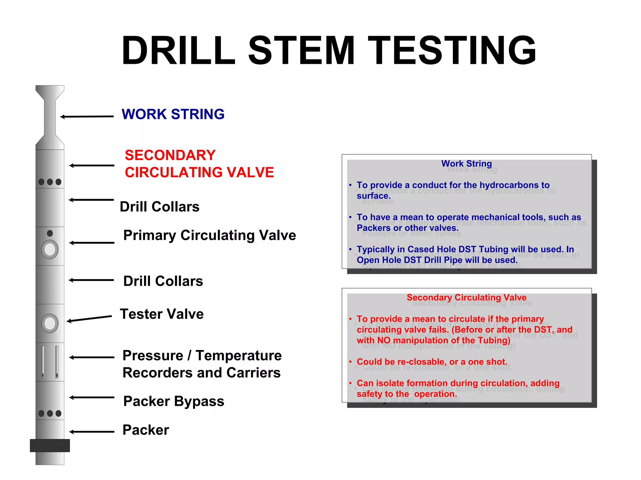
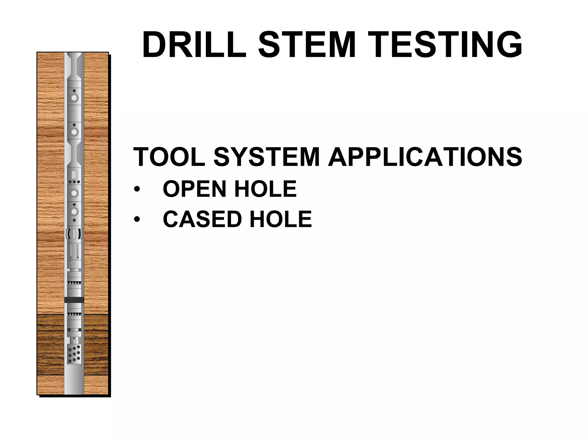
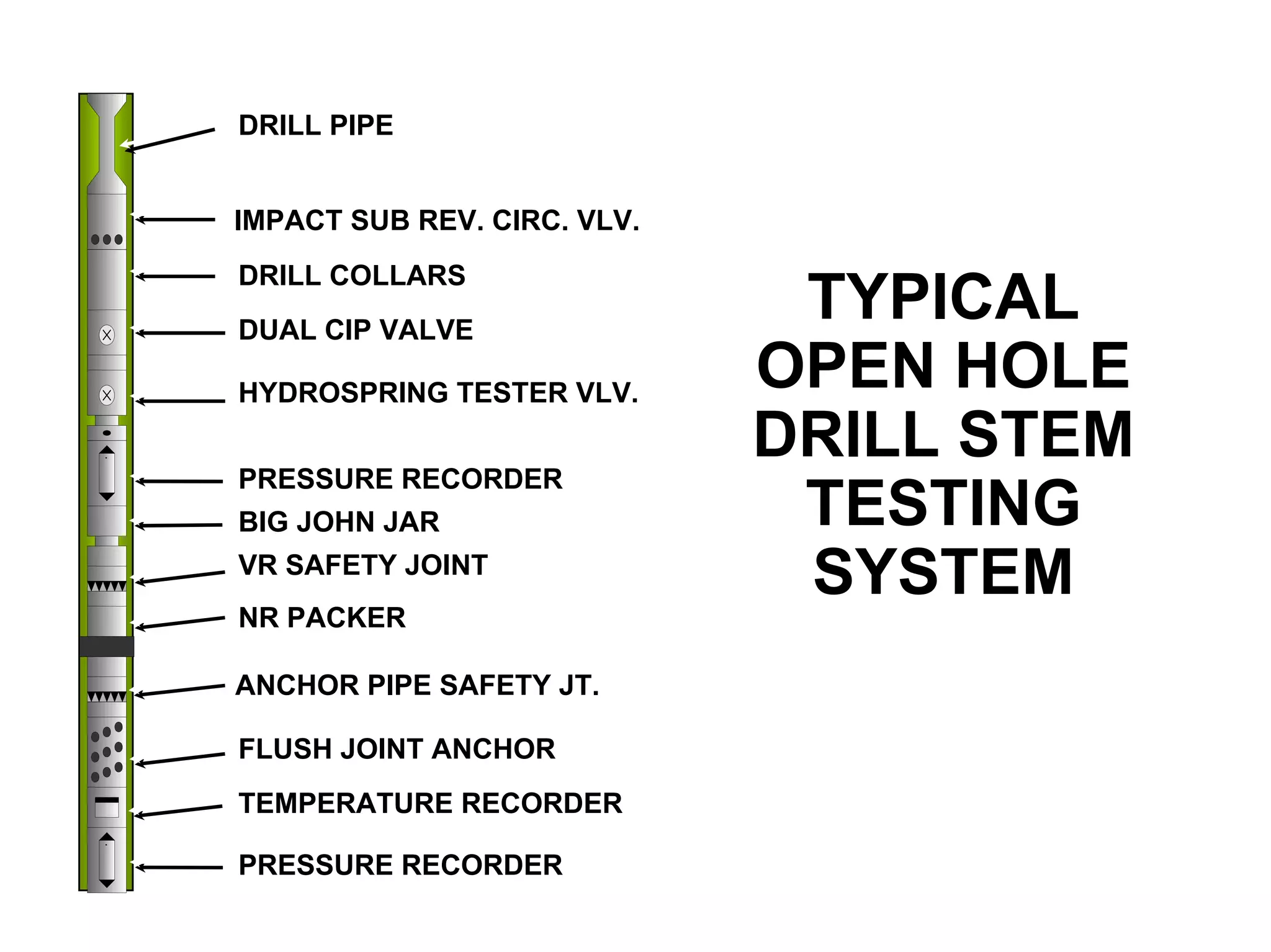
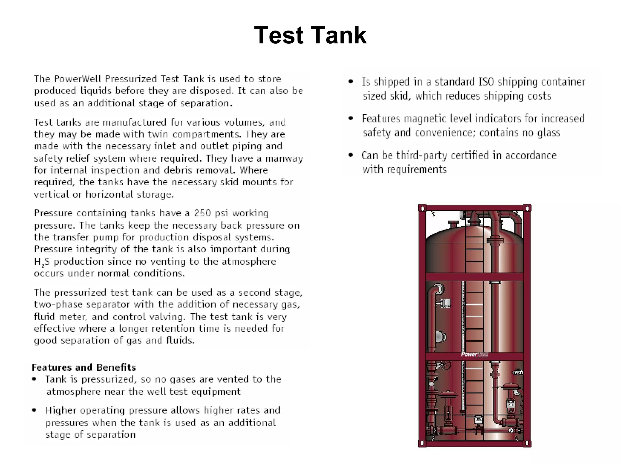
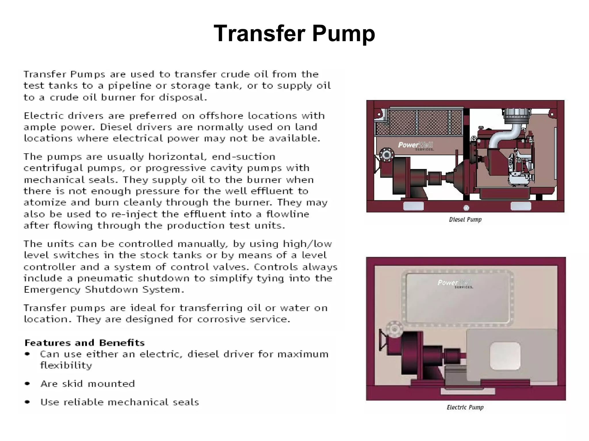
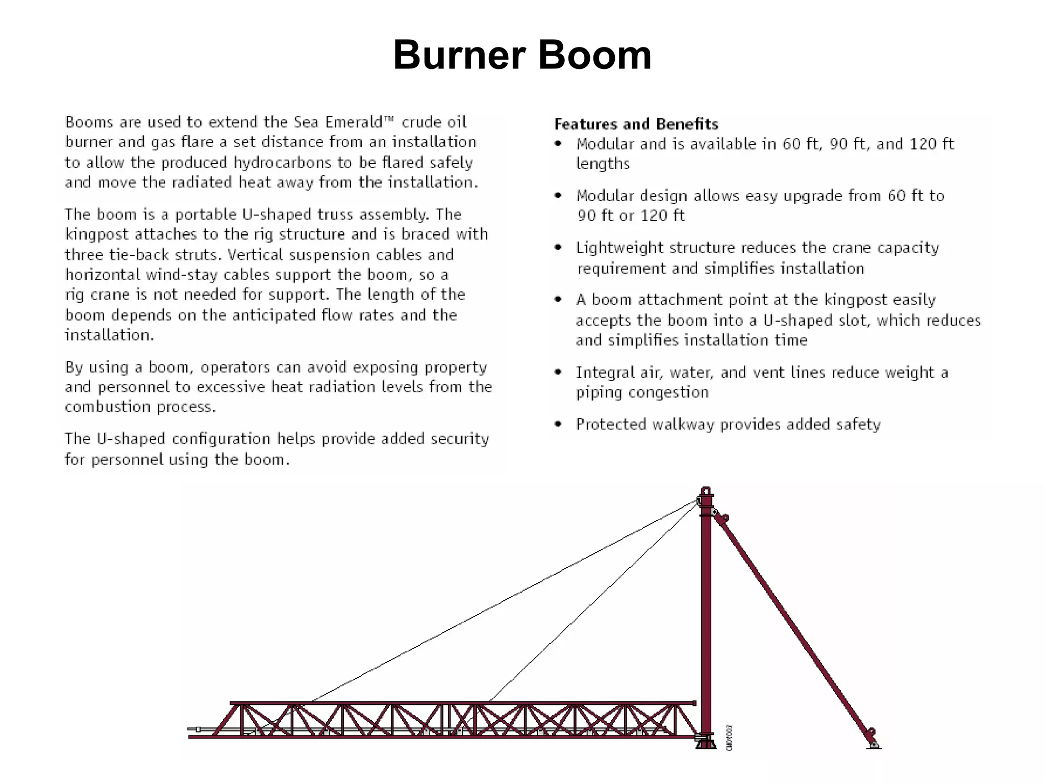
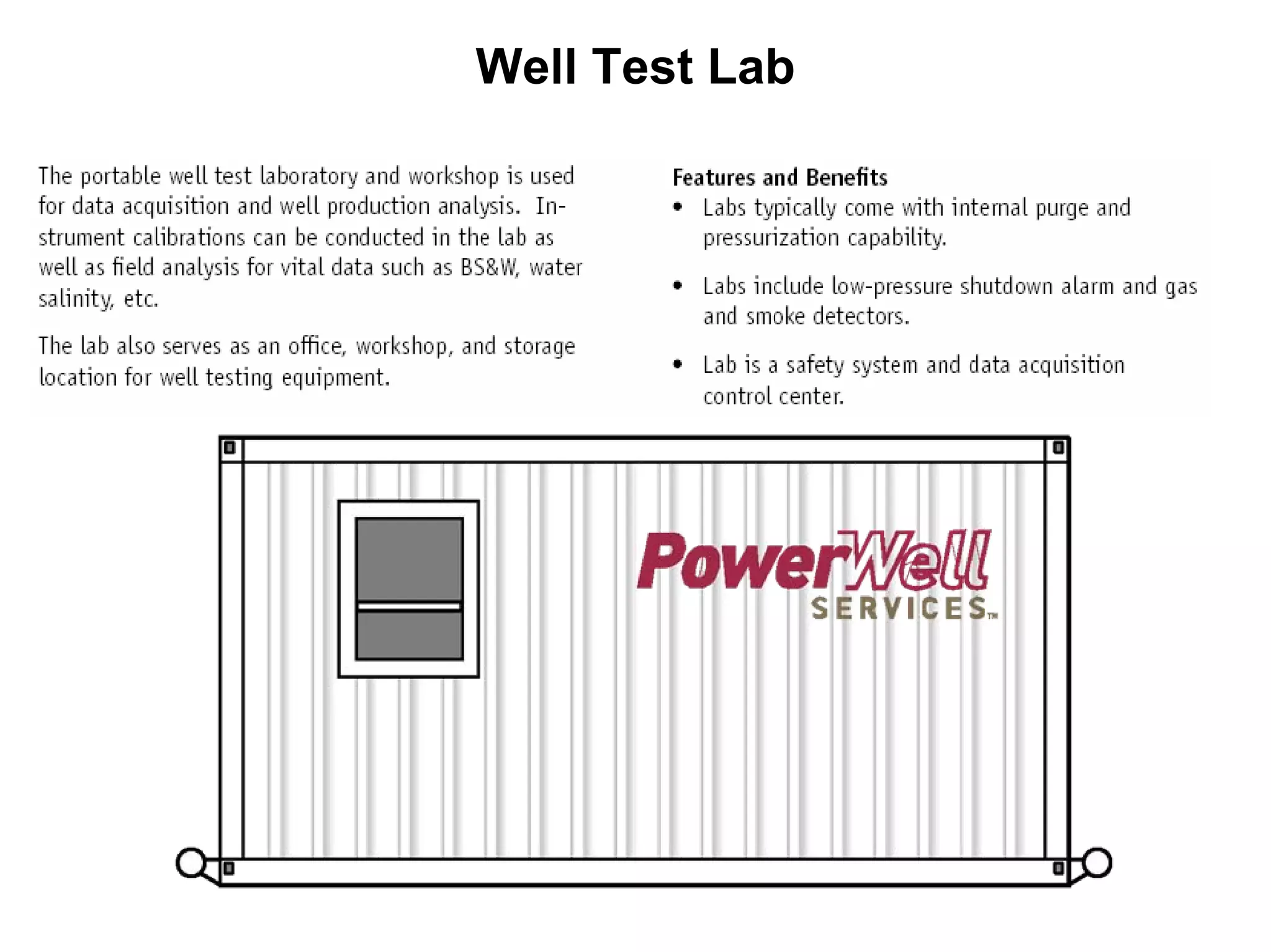
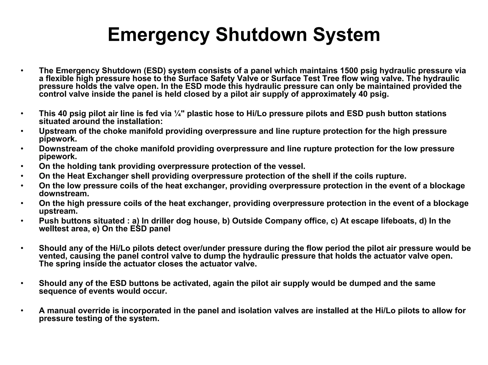
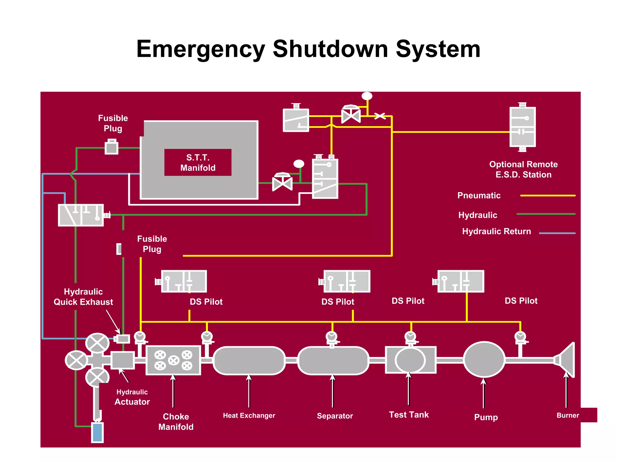
By
R. Harry Eddyarso
PT. SARIPARI PERTIWI ABADI
“KMI Goes to Campus Program”
Komunitas Migas Indonesia – Universitas Trisakti
25 November 2006
WE DO APPRECIATE HALLIBURTON AND POWER
WELL SERVICE GROUPS FOR PROVIDING THE WELL
TESTING PRESENTATION MATERIALS FOR LESSON
LEARNED SHARING AND EDUCATIONAL PURPOSES
…….
STATEMENT of APPRECIATION
Finding The Reservoir : Seismic Survey
Making Access to The Reservoir : Drilling
Optimizing The Reservoir : Testing
Evaluating The Reservoir : Logging
Producing The Reservoir : Completion
SEISMIC ALONG WELL PATH
3D DATA
Depth Structure Map
Top B-29A2 Base B-29A2
c.i =25’
Types Of Well Testing Equipment
• DST
(Drill Stem Testing)
DST
Open Hole Cased Hole Barefoot
• STE (Surface
Testing Eqpt.)
STE
Exploration Clean Ups Production
Guide to Better Service and Correct
Sizing of Equipment
Guide to Better Service and Correct
Sizing of Equipment
1. What is the estimated highest pressure at
the wellhead ?.
2. What is the lowest pressure at wellhead ?.
3. What are the expected maximum and
minimum effluent rates ?. Gas/Oil/Water ?.
4. Is the effluent sweet or does it contain
corrosives ?. If it does contain corrosives,
what are the expected highest concentrations of
H2S (This will also include CO2 amounts).
Guide to Better Service and Correct
Sizing of Equipment (Continued)
Guide to Better Service and Correct
Sizing of Equipment (Continued)
5. What is the expected A.P.I. of liquid hydrocarbon
and the specific gravity of gas ?.
6. What is the customer’s requirement for disposal
or storing of liquid hydrocarbon and H2O ?.
7. Are there any special requirements such as
governing bodies’ special rules or regulations,
i.e., maximum weight restrictions, etc. ?.
DRILL STEM TESTING
Definition
• Temporary completion of a well to gather
reservoir data and information for
evaluation.
• Measurement of formation parameters and
characteristics are under dynamic
conditions. Disturbance (flow) of the
formation is measured (Pressure
transient).
Objectives
• Identify the formation
fluid
• Determine the rate at
which fluids can be
produced
• Determine reservoir
parameters
(Productivity, Permeability,
Well Bore Damage, etc )
• Calculating the
Economic Feasibility
of the Well
DRILL STEM TESTING
SECONDARY
CIRCULATING VLV.
DRILL COLLARS
PRIMARY
CIRCULATING VLV.
TESTER VLV.
WORK STRING
PRESSURE /
TEMPERATURE RECORDERS
PACKER BYPASS
PACKER
DRILL COLLARS
DRILL STEM TESTING
PACKER
• Will safely separate well in two sections.
• Will protect formation
• Allow flowing the well inside Tubing while Isolating
the Annulus
PACKER
• Will safely separate well in two sections.
• Will protect formation
• Allow flowing the well inside Tubing while Isolating
the Annulus
PACKER By Pass
• Will divert mud while tripping in and out of the hole.
• Will protect Packer elements during circulation.
• Allow equalization of differential pressure when
unsetting packer
PACKER By Pass
• Will divert mud while tripping in and out of the hole.
• Will protect Packer elements during circulation.
• Allow equalization of differential pressure when
unsetting packer
Pressure Temperature Recorders
• Will record pressure transient
• Must be carried safely and must be protected.
• Location in the string can vary.
• Multiple options exists
Pressure Temperature Recorders
• Will record pressure transient
• Must be carried safely and must be protected.
• Location in the string can vary.
• Multiple options exists
SECONDARY
CIRCULATING VALVE
DRILL COLLARS
PRIMARY
CIRCULATING VALVE
TESTER VALVE
WORK STRING
Pressure / Temperature
Recorders and Carriers
Packer Bypass
Packer
DRILL COLLARS
DRILL STEM TESTING
Tester Valve
• Will provide DOWN HOLE closure.
• Will add a safety barrier. Allow pressure control
inside the string.
• Various types, some allow to “Lock Open” and can
be reversed to “Normal Mode”.
Tester Valve
• Will provide DOWN HOLE closure.
• Will add a safety barrier. Allow pressure control
inside the string.
• Various types, some allow to “Lock Open” and can
be reversed to “Normal Mode”.
Drill Collars
• Will provide a SAFE separation between Ball Valves.
• Will add weight to packer protecting the Tubing.
Drill Collars
• Will provide a SAFE separation between Ball Valves.
• Will add weight to packer protecting the Tubing.
Primary Circulating Valve
• Will provide a mean to circulate without unsetting the
packer. (Before and/or after the DST, and with NO
manipulation of the Tubing)
• Will be re-closable.
• Can isolate formation during circulation, adding
safety to the operation.
Primary Circulating Valve
• Will provide a mean to circulate without unsetting the
packer. (Before and/or after the DST, and with NO
manipulation of the Tubing)
• Will be re-closable.
• Can isolate formation during circulation, adding
safety to the operation.
SECONDARY
CIRCULATING VALVE
Drill Collars
Primary Circulating Valve
Tester Valve
WORK STRING
Pressure / Temperature
Recorders and Carriers
Packer Bypass
Packer
Drill Collars
DRILL STEM TESTING
Secondary Circulating Valve
• To provide a mean to circulate if the primary
circulating valve fails. (Before or after the DST, and
with NO manipulation of the Tubing)
• Could be re-closable, or a one shot.
• Can isolate formation during circulation, adding
safety to the operation.
Secondary Circulating Valve
• To provide a mean to circulate if the primary
circulating valve fails. (Before or after the DST, and
with NO manipulation of the Tubing)
• Could be re-closable, or a one shot.
• Can isolate formation during circulation, adding
safety to the operation.
Work String
• To provide a conduct for the hydrocarbons to
surface.
• To have a mean to operate mechanical tools, such as
Packers or other valves.
• Typically in Cased Hole DST Tubing will be used. In
Open Hole DST Drill Pipe will be used.
Work String
• To provide a conduct for the hydrocarbons to
surface.
• To have a mean to operate mechanical tools, such as
Packers or other valves.
• Typically in Cased Hole DST Tubing will be used. In
Open Hole DST Drill Pipe will be used.
TOOL SYSTEM APPLICATIONS
• OPEN HOLE
• CASED HOLE
DRILL STEM TESTING
TYPICAL
OPEN HOLE
DRILL STEM
TESTING
SYSTEM
IMPACT SUB REV. CIRC. VLV.
DRILL PIPE
DRILL COLLARS
DUAL CIP VALVE
HYDROSPRING TESTER VLV.
PRESSURE RECORDER
VR SAFETY JOINT
ANCHOR PIPE SAFETY JT.
TEMPERATURE RECORDER
NR PACKER
BIG JOHN JAR
FLUSH JOINT ANCHOR
PRESSURE RECORDER
TYPICAL
CASED HOLE
DRILL STEM
TESTING
SYSTEM
RD SAFETY CIRCULATING VLV.
PREMIUM THREADED TUBING
DRILL COLLARS
EXPRESS CIRCULATING VLV.
SURFACE READOUT SYSTEM
SELECT TESTER VLV.
MPV VALVE
PRESSURE / TEMPERATURE REC.
CHAMP IV PACKER
VERTICAL SHOCK ABSORBER
TIME DELAY FIRING HEAD
R/A TAG SUB
BIG JOHN JAR
RTTS SAFETY JOINT
WORK STRING
RADIAL SHOCK ABSORBER
VANN GUNS
BELOW PKR. HYD. SAFETY JOINT
Surface Well Test Package
Surface Test Tree
Data Header
Choke Manifold
Steam Heat Exchanger
Indirect Fired Heater
Separator
Test Tank
Transfer Pump
Burner Boom
Burner Head
Air Inlet
Oil Inlet
Igniter Connections
Nozzle
Gas
Jets
Pilot
Chemical Injection Pump
Well Test Lab
Air Compressor
SCAN (Surface Computerized Acquisition Network)
– PowerWell Services SCAN combines the most up-to date electronic hardware
and data gathering software for unbeatable performance during well test
operations.
– Present equipment consists of Computer and peripherals connected to
transducers and transmitters measuring pressure, temperature, and flow rates.
Data Acquisition
0
1000
2000
3000
4000
5000
6000
7000
8000
9000
10000
11000
12000
13000
14000
15000
16000
10/2712:00:00
10/2800:00:00
10/2812:00:00
10/2900:00:00
10/2912:00:00
10/3000:00:00
10/3012:00:00
10/3100:00:00
10/3112:00:00
11/0100:00:00
11/0112:00:00
11/0200:00:00
11/0212:00:00
11/0300:00:00
11/0312:00:00
11/0400:00:00
11/0412:00:00
11/0500:00:00
11/0512:00:00
11/0600:00:00
Pressure(psi)
Time (mm/dd hh:mm:ss)
60
80
100
120
140
160
180
200
220
240
260
Temperature(°F)
Pressure Inflection Point Temperature
Pressure up
tubing to fire
the guns
Shut in at the choke
manifold and cycle
the OMNI to spot
diesel to lower the
hydrostatic head
Pre-stimulation flow
period for formation
cleanup.
Acidising the formation by
bullheading from surface
Post-Stimulation
flowback and cleanup
Steady flow on
a small choke
Pressure buildup
Second flow period
for sample catching
Pressure & Temperature History Plot for Marrat Object II
Reporting Formats
The Software Gives The Operator The Ability To Create Custom Report Formats
And Save Them For Later Use
Emergency Shutdown System
• The Emergency Shutdown (ESD) system consists of a panel which maintains 1500 psig hydraulic pressure via
a flexible high pressure hose to the Surface Safety Valve or Surface Test Tree flow wing valve. The hydraulic
pressure holds the valve open. In the ESD mode this hydraulic pressure can only be maintained provided the
control valve inside the panel is held closed by a pilot air supply of approximately 40 psig.
• This 40 psig pilot air line is fed via ¼" plastic hose to Hi/Lo pressure pilots and ESD push button stations
situated around the installation:
• Upstream of the choke manifold providing overpressure and line rupture protection for the high pressure
pipework.
• Downstream of the choke manifold providing overpressure and line rupture protection for the low pressure
pipework.
• On the holding tank providing overpressure protection of the vessel.
• On the Heat Exchanger shell providing overpressure protection of the shell if the coils rupture.
• On the low pressure coils of the heat exchanger, providing overpressure protection in the event of a blockage
downstream.
• On the high pressure coils of the heat exchanger, providing overpressure protection in the event of a blockage
upstream.
• Push buttons situated : a) In driller dog house, b) Outside Company office, c) At escape lifeboats, d) In the
welltest area, e) On the ESD panel
• Should any of the Hi/Lo pilots detect over/under pressure during the flow period the pilot air pressure would be
vented, causing the panel control valve to dump the hydraulic pressure that holds the actuator valve open.
The spring inside the actuator closes the actuator valve.
• Should any of the ESD buttons be activated, again the pilot air supply would be dumped and the same
sequence of events would occur.
• A manual override is incorporated in the panel and isolation valves are installed at the Hi/Lo pilots to allow for
pressure testing of the system.
Emergency Shutdown System
Fusible
Plug
S.T.T.
Manifold Optional Remote
E.S.D. Station
Pneumatic
Hydraulic
Hydraulic Return
Hydraulic
Quick Exhaust
Fusible
Plug
DS Pilot DS Pilot DS Pilot DS Pilot
Hydraulic
Actuator
Choke
Manifold
Heat Exchanger Separator Test Tank Pump Burner
05 well testing   trisakti 25 nov 2007

05 well testing trisakti 25 nov 2007

  • 1.
    By R. Harry Eddyarso PT.SARIPARI PERTIWI ABADI “KMI Goes to Campus Program” Komunitas Migas Indonesia – Universitas Trisakti 25 November 2006
  • 2.
    WE DO APPRECIATEHALLIBURTON AND POWER WELL SERVICE GROUPS FOR PROVIDING THE WELL TESTING PRESENTATION MATERIALS FOR LESSON LEARNED SHARING AND EDUCATIONAL PURPOSES ……. STATEMENT of APPRECIATION
  • 3.
    Finding The Reservoir: Seismic Survey Making Access to The Reservoir : Drilling Optimizing The Reservoir : Testing Evaluating The Reservoir : Logging Producing The Reservoir : Completion
  • 4.
    SEISMIC ALONG WELLPATH 3D DATA
  • 5.
    Depth Structure Map TopB-29A2 Base B-29A2 c.i =25’
  • 6.
    Types Of WellTesting Equipment • DST (Drill Stem Testing) DST Open Hole Cased Hole Barefoot • STE (Surface Testing Eqpt.) STE Exploration Clean Ups Production
  • 7.
    Guide to BetterService and Correct Sizing of Equipment Guide to Better Service and Correct Sizing of Equipment 1. What is the estimated highest pressure at the wellhead ?. 2. What is the lowest pressure at wellhead ?. 3. What are the expected maximum and minimum effluent rates ?. Gas/Oil/Water ?. 4. Is the effluent sweet or does it contain corrosives ?. If it does contain corrosives, what are the expected highest concentrations of H2S (This will also include CO2 amounts).
  • 8.
    Guide to BetterService and Correct Sizing of Equipment (Continued) Guide to Better Service and Correct Sizing of Equipment (Continued) 5. What is the expected A.P.I. of liquid hydrocarbon and the specific gravity of gas ?. 6. What is the customer’s requirement for disposal or storing of liquid hydrocarbon and H2O ?. 7. Are there any special requirements such as governing bodies’ special rules or regulations, i.e., maximum weight restrictions, etc. ?.
  • 10.
    DRILL STEM TESTING Definition •Temporary completion of a well to gather reservoir data and information for evaluation. • Measurement of formation parameters and characteristics are under dynamic conditions. Disturbance (flow) of the formation is measured (Pressure transient).
  • 11.
    Objectives • Identify theformation fluid • Determine the rate at which fluids can be produced • Determine reservoir parameters (Productivity, Permeability, Well Bore Damage, etc ) • Calculating the Economic Feasibility of the Well DRILL STEM TESTING
  • 12.
    SECONDARY CIRCULATING VLV. DRILL COLLARS PRIMARY CIRCULATINGVLV. TESTER VLV. WORK STRING PRESSURE / TEMPERATURE RECORDERS PACKER BYPASS PACKER DRILL COLLARS DRILL STEM TESTING PACKER • Will safely separate well in two sections. • Will protect formation • Allow flowing the well inside Tubing while Isolating the Annulus PACKER • Will safely separate well in two sections. • Will protect formation • Allow flowing the well inside Tubing while Isolating the Annulus PACKER By Pass • Will divert mud while tripping in and out of the hole. • Will protect Packer elements during circulation. • Allow equalization of differential pressure when unsetting packer PACKER By Pass • Will divert mud while tripping in and out of the hole. • Will protect Packer elements during circulation. • Allow equalization of differential pressure when unsetting packer Pressure Temperature Recorders • Will record pressure transient • Must be carried safely and must be protected. • Location in the string can vary. • Multiple options exists Pressure Temperature Recorders • Will record pressure transient • Must be carried safely and must be protected. • Location in the string can vary. • Multiple options exists
  • 13.
    SECONDARY CIRCULATING VALVE DRILL COLLARS PRIMARY CIRCULATINGVALVE TESTER VALVE WORK STRING Pressure / Temperature Recorders and Carriers Packer Bypass Packer DRILL COLLARS DRILL STEM TESTING Tester Valve • Will provide DOWN HOLE closure. • Will add a safety barrier. Allow pressure control inside the string. • Various types, some allow to “Lock Open” and can be reversed to “Normal Mode”. Tester Valve • Will provide DOWN HOLE closure. • Will add a safety barrier. Allow pressure control inside the string. • Various types, some allow to “Lock Open” and can be reversed to “Normal Mode”. Drill Collars • Will provide a SAFE separation between Ball Valves. • Will add weight to packer protecting the Tubing. Drill Collars • Will provide a SAFE separation between Ball Valves. • Will add weight to packer protecting the Tubing. Primary Circulating Valve • Will provide a mean to circulate without unsetting the packer. (Before and/or after the DST, and with NO manipulation of the Tubing) • Will be re-closable. • Can isolate formation during circulation, adding safety to the operation. Primary Circulating Valve • Will provide a mean to circulate without unsetting the packer. (Before and/or after the DST, and with NO manipulation of the Tubing) • Will be re-closable. • Can isolate formation during circulation, adding safety to the operation.
  • 14.
    SECONDARY CIRCULATING VALVE Drill Collars PrimaryCirculating Valve Tester Valve WORK STRING Pressure / Temperature Recorders and Carriers Packer Bypass Packer Drill Collars DRILL STEM TESTING Secondary Circulating Valve • To provide a mean to circulate if the primary circulating valve fails. (Before or after the DST, and with NO manipulation of the Tubing) • Could be re-closable, or a one shot. • Can isolate formation during circulation, adding safety to the operation. Secondary Circulating Valve • To provide a mean to circulate if the primary circulating valve fails. (Before or after the DST, and with NO manipulation of the Tubing) • Could be re-closable, or a one shot. • Can isolate formation during circulation, adding safety to the operation. Work String • To provide a conduct for the hydrocarbons to surface. • To have a mean to operate mechanical tools, such as Packers or other valves. • Typically in Cased Hole DST Tubing will be used. In Open Hole DST Drill Pipe will be used. Work String • To provide a conduct for the hydrocarbons to surface. • To have a mean to operate mechanical tools, such as Packers or other valves. • Typically in Cased Hole DST Tubing will be used. In Open Hole DST Drill Pipe will be used.
  • 15.
    TOOL SYSTEM APPLICATIONS •OPEN HOLE • CASED HOLE DRILL STEM TESTING
  • 16.
    TYPICAL OPEN HOLE DRILL STEM TESTING SYSTEM IMPACTSUB REV. CIRC. VLV. DRILL PIPE DRILL COLLARS DUAL CIP VALVE HYDROSPRING TESTER VLV. PRESSURE RECORDER VR SAFETY JOINT ANCHOR PIPE SAFETY JT. TEMPERATURE RECORDER NR PACKER BIG JOHN JAR FLUSH JOINT ANCHOR PRESSURE RECORDER
  • 17.
    TYPICAL CASED HOLE DRILL STEM TESTING SYSTEM RDSAFETY CIRCULATING VLV. PREMIUM THREADED TUBING DRILL COLLARS EXPRESS CIRCULATING VLV. SURFACE READOUT SYSTEM SELECT TESTER VLV. MPV VALVE PRESSURE / TEMPERATURE REC. CHAMP IV PACKER VERTICAL SHOCK ABSORBER TIME DELAY FIRING HEAD R/A TAG SUB BIG JOHN JAR RTTS SAFETY JOINT WORK STRING RADIAL SHOCK ABSORBER VANN GUNS BELOW PKR. HYD. SAFETY JOINT
  • 19.
  • 20.
  • 21.
  • 22.
  • 23.
  • 24.
  • 25.
  • 26.
  • 27.
  • 28.
  • 29.
    Burner Head Air Inlet OilInlet Igniter Connections Nozzle Gas Jets Pilot
  • 30.
  • 31.
  • 33.
  • 34.
    SCAN (Surface ComputerizedAcquisition Network) – PowerWell Services SCAN combines the most up-to date electronic hardware and data gathering software for unbeatable performance during well test operations. – Present equipment consists of Computer and peripherals connected to transducers and transmitters measuring pressure, temperature, and flow rates.
  • 35.
  • 36.
    0 1000 2000 3000 4000 5000 6000 7000 8000 9000 10000 11000 12000 13000 14000 15000 16000 10/2712:00:00 10/2800:00:00 10/2812:00:00 10/2900:00:00 10/2912:00:00 10/3000:00:00 10/3012:00:00 10/3100:00:00 10/3112:00:00 11/0100:00:00 11/0112:00:00 11/0200:00:00 11/0212:00:00 11/0300:00:00 11/0312:00:00 11/0400:00:00 11/0412:00:00 11/0500:00:00 11/0512:00:00 11/0600:00:00 Pressure(psi) Time (mm/dd hh:mm:ss) 60 80 100 120 140 160 180 200 220 240 260 Temperature(°F) PressureInflection Point Temperature Pressure up tubing to fire the guns Shut in at the choke manifold and cycle the OMNI to spot diesel to lower the hydrostatic head Pre-stimulation flow period for formation cleanup. Acidising the formation by bullheading from surface Post-Stimulation flowback and cleanup Steady flow on a small choke Pressure buildup Second flow period for sample catching Pressure & Temperature History Plot for Marrat Object II
  • 37.
    Reporting Formats The SoftwareGives The Operator The Ability To Create Custom Report Formats And Save Them For Later Use
  • 38.
    Emergency Shutdown System •The Emergency Shutdown (ESD) system consists of a panel which maintains 1500 psig hydraulic pressure via a flexible high pressure hose to the Surface Safety Valve or Surface Test Tree flow wing valve. The hydraulic pressure holds the valve open. In the ESD mode this hydraulic pressure can only be maintained provided the control valve inside the panel is held closed by a pilot air supply of approximately 40 psig. • This 40 psig pilot air line is fed via ¼" plastic hose to Hi/Lo pressure pilots and ESD push button stations situated around the installation: • Upstream of the choke manifold providing overpressure and line rupture protection for the high pressure pipework. • Downstream of the choke manifold providing overpressure and line rupture protection for the low pressure pipework. • On the holding tank providing overpressure protection of the vessel. • On the Heat Exchanger shell providing overpressure protection of the shell if the coils rupture. • On the low pressure coils of the heat exchanger, providing overpressure protection in the event of a blockage downstream. • On the high pressure coils of the heat exchanger, providing overpressure protection in the event of a blockage upstream. • Push buttons situated : a) In driller dog house, b) Outside Company office, c) At escape lifeboats, d) In the welltest area, e) On the ESD panel • Should any of the Hi/Lo pilots detect over/under pressure during the flow period the pilot air pressure would be vented, causing the panel control valve to dump the hydraulic pressure that holds the actuator valve open. The spring inside the actuator closes the actuator valve. • Should any of the ESD buttons be activated, again the pilot air supply would be dumped and the same sequence of events would occur. • A manual override is incorporated in the panel and isolation valves are installed at the Hi/Lo pilots to allow for pressure testing of the system.
  • 39.
    Emergency Shutdown System Fusible Plug S.T.T. ManifoldOptional Remote E.S.D. Station Pneumatic Hydraulic Hydraulic Return Hydraulic Quick Exhaust Fusible Plug DS Pilot DS Pilot DS Pilot DS Pilot Hydraulic Actuator Choke Manifold Heat Exchanger Separator Test Tank Pump Burner