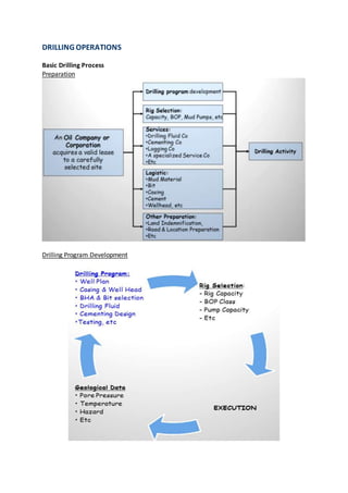
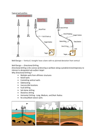
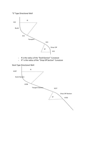
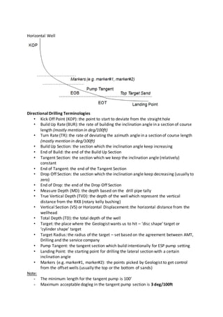
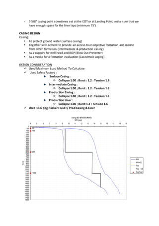
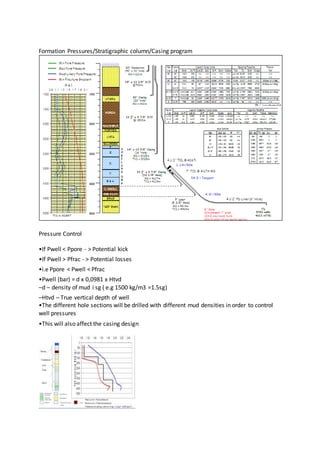
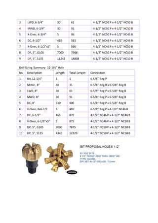
DRILLING OPERATIONS
Basic Drilling Process
Preparation
Drilling Program Development
Typical well profiles
Well Design --- Vertical / straight: have a bore with no planned deviation from vertical
Well Design --- Directional Drilling
Directional drilling is the science of directing a wellbore along a predetermined trajectory to
intersect a designated sub-surface target
Why Directional Drilling ?
 Multiple wells from offshore structures
 Relief wells
 Controlling vertical wells
 Sidetracking
 Inaccessible locations
 Fault drilling
 Salt dome drilling
 Shoreline drilling
 Horizontal Drilling - Long, Medium, and Short Radius
 Re-entry/Multi-lateral wells
Directional Well Types
“J” Type Directional Well (Build and Hold Type)
R
KOP
TVD1
TVD2
VS1
VS2
MD2Inc
Target
TD
“S” Type Directional Well
- R is the radius of the “Build Section” Curvature
- R” is the radius of the “Drop Off Section” Curvature
Slant Type Directional Well
R
KO
P
Build
Section
EO
B
R”
Tangent
Section
Drop Off
Section
EO
T
EO
D
R
KOP
Build Section
EOB
R”
Tangent Section
Drop Off Section
EOT
EOD
Horizontal Well
Directional Drilling Terminologies
• Kick Off Point (KOP): the point to start to deviate from the straight hole
• Build Up Rate (BUR): the rate of building the inclination angle in a section of course
length (mostly mention in deg/100ft)
• Turn Rate (TR): the rate of deviating the azimuth angle in a section of course length
(mostly mention in deg/100ft)
• Build Up Section: the section which the inclination angle keep increasing
• End of Build: the end of the Build Up Section
• Tangent Section: the section which we keep the inclination angle (relatively)
constant
• End of Tangent: the end of the Tangent Section
• Drop Off Section: the section which the inclination angle keep decreasing (usually to
zero)
• End of Drop: the end of the Drop Off Section
• Measure Depth (MD): the depth based on the drill pipe tally
• True Vertical Depth (TVD): the depth of the well which represent the vertical
distance from the RKB (rotary kelly bushing)
• Vertical Section (VS) or Horizontal Displacement: the horizontal distance from the
wellhead
• Total Depth (TD): the total depth of the well
• Target: the place where the Geologist wants us to hit – ‘disc shape’ target or
‘cylinder shape’ target
• Target Radius: the radius of the target – set based on the agreement between AMT,
Drilling and the service company
• Pump Tangent: the tangent section which build intentionally for ESP pump setting
• Landing Point: the starting point for drilling the lateral section with a certain
inclination angle
• Markers (e.g. marker#1, marker#2): the points picked by Geologist to get control
from the offset wells (usually the top or the bottom of sands)
Note:
- The minimum length for the tangent pump is 100’
- Maximum acceptable dogleg in the tangent pump section is 3 deg/100ft
- 9 5/8” casing point sometimes set at the EOT or at Landing Point, make sure that we
have enough space for the liner laps (minimum 75’)
CASING DESIGN
Casing:
• To protect ground water (surface casing)
• Together with cement to provide an access to an objective formation and isolate
from other formation (intermediate & production casing)
• As a support for well head and BOP (Blow Out Preventer)
• As a media for a formation evaluation (Cased Hole Loging)
DESIGN CONSIDERATION
 Used Maximum Load Method To Calculate
 Used Safety Factors :
Surface Casing :
 Collapse 1.00 : Burst : 1.2 : Tension 1.6
Intermediate Casing :
 Collapse 1.00 ; Burst : 1.2 : Tension 1.6
Production Casing :
 Collapse 1.00 ; Burst : 1.2 : Tension 1.6
Production Liner :
 Collapse 1.00 ; Burst 1.2 ; Tension 1.6
 Used 13.6 ppg Packer Fluid F/ Prod Casing & Liner
Casing Seat Selection (Refine)
350
1000
6200
11400
0
500
1000
1500
2000
2500
3000
3500
4000
4500
5000
5500
6000
6500
7000
7500
8000
8500
9000
9500
10000
10500
11000
11500
12000
12500
13000
13500
14000
14500
15000
15500
16000
16500
17000
17500
18000
4 5 6 7 8 9 10 11 12 13 14 15 16 17 18 19
MW (ppg)
TVD
MW
MW+0.2
Frac
Frac - 0.5
Csg Seat
CASING SELECTION & SETTING DEPTH
Casing Size Grade & Connection Setting Depth
Surface 18 5/8” K55 - 87.5 #, BTC 1000 ft
Intermediate 13 3/8” K55 - 68 # BTC 6200 ft
Production 9 7/8” Q 125 - 62.8 # LTC 11400 ft (12220 ft MD)
Liner 7 5/8” Q 125 – 42.8 # LTC 14496 ft (18807 ft MD)
Formation Pressures/Stratigraphic column/Casing program
Pressure Control
•If Pwell < Ppore - > Potential kick
•If Pwell > Pfrac - > Potential losses
•i.e Ppore < Pwell < Pfrac
•Pwell (bar) = d x 0,0981 x Htvd
–d – density of mud i sg ( e.g 1500 kg/m3 =1.5sg)
–Htvd – True vertical depth of well
•The different hole sections will be drilled with different mud densities in order to control
well pressures
•This will also affect the casing design
LINER CASING
5.- DIÁMETER MEAN THROW CALIPER AND VOLUME CEMENT
TOPE LAV S/DP 90.27
8341 8.500
30.00
TOPE LAV S/DP 7.927
9315
-66.77 FECTO
TOPE ESP S/DP -60.27 FECTO
10248
V7 6.- VOLUME THEORICS AND REAL TAIL SLURRY
11414 TOPE CEM C/DP
11620 TOPE CEM S/DP V1= 2.0 BLS V3= 90.3 BLS V5= 21.7 BLS
V2= 0.1 BLS V4= 4.7 BLS VD= 485.7 BLS
V2R= 0.1 BLS V3R= 30.0 BLS
TOPE COLGADOR V6= 280.7 BLS V7= 205.0 BLS
11920
a.- VOLUME SLURRY BY CALIPER W/O EXCESS:
V4 V4
58 BLS
b.- PERCENT AND VOLUME SLURRY BY EXCESS:
ZAP. 9-5/8"
12220
c.- VOLUME SLURRY BY CALIPER W/EXCESS:
V6
61 BLS
d.- PRE-FLOW:
130.0 BLS
e.- QUANTITY SACKS MEAN SLURRY:
V3 V3 1.44 (FT^3/SXS)
228 (SXS)
240 (SXS)
LANDING C.
18757 f.-VOLUME DISPLACEMENT:
485.7 BLS
V1
ZAP.7"
18806
V2 NUMB OD ID LONG TOP / MD
412 5.000 4.276 12,785.00 -878
MD 1 7.879 4.572 6.00 11907
1 7.883 7.349 6.33 11913
1 7.375 6.413 0.45 11926
1 8.125 5.999 6.85 11920
1 7.635 4.893 0.70 11926
152 5.500 4.892 6,830.00 11927
1 6.050 4.899 0.93 18757
1 5.500 4.892 45.00 18758
1 5.629 2.000 3.00 18803
18806
18807
3.0
THEORIC VOLUME
REAL VOLUME BY CALIPER
61
PERCENT EXCESS (+) DEFECT (-) THROW CALIPER (%) =
VOLUME EXCESS (+) DEFECT (-) THROW CALIPER (BLS) =V7
V6 V6
V9 V9
HOLE DEPTH
SHOE DEPTH
SHOE 7-5/8"
LINER 7-5/8"
X/O
MECHANICS HANGER
QUANTITY SACKS CEMENT W/O EXCESS PERCENT =
VOLUME PRE-FLOW =
VOLUME EXCESS (BLS) =
VD = V6 + V7
QUANTITY SACKS CEMENT W/EXCESS PERCENT =
NEW VOLUME SLURRY W / EXCESS =
VL = V1+V2R+V3R+V4+V5
LANDING COLLAR 7-5/8"
LINER 7-5/8"
TIE BACK
DP 5" S-135 19,5 PPF
18807
SETTING TOOL
X/O
SCHEDULE LINER 7-5/8"
DESCRIPTION
RENDIMIENTO =
PERCENT EXCESS (%) = 10.0
VOLUME DISPLACEMENT
VOLUME TAIL SLURRY (BLS) =
V5 V5
V8 V8
DIAMETER THEORIC HOLE (IN)=
VOLUME REAL ANNULAR FROM CÁLIPER HOLE-LINER 7-5/8" (BLS)=
DIAMETER REAL HOLE FROM CÁLIPER (INCH) =
VOLUME THEORIC. ANNULAR HOLE-LINER 7-5/8" (BLS) =
V7
Wellhead Selection
• Wellhead & Tree Selection
– Based on API Specification 6A
– Offset Well: OCS-G-1241 #26
• PSL Level: PSL-3
• API Pressure Rating: 15,000 psi
– MASP plus 20% = 11,000psi
• API Temperature Class: U
– 80oF to 240oF
• Material Class: General Service
Tree & Wellhead Equipment
• Tree
– Size: 3.5”
– Type: Single
– MSP: 15,000 psi
– Tubing Hanger for 3.5” NUE Tubing
• Wellhead
– 18 5/8” Csg Head: 2000 psi
– 13 3/8” Csg Spool: 5000 psi
– 9 7/8” Tbg Spool: 15,000 psi w/ 3.5” Tbg Hng
– 7 5/8” Liner Hanger: 15,000 psi
Bottom Hole Assembly
• Drill Pipe, Heavy Weight Drill Pipe, Dill Collar, Bit
• To transfer rotation from surface to the bit
• To provide sufficient weight for drilling
• To transfer drilling fluid from surface to bottom (hydraulic)
Objectives
• Minimize failure
• Use current tubular inventory
• Achieve directional target
• Maximum stress < Yield stress
• Retard fatigue
• Resist H2S
General Well Plan
Hole Size MD TVD Angle Max WOB
22” 1000 1000 0 25k
17-1/2” 6200 6200 0 35k
12-1/4” 12220 11400 62 45k
8-1/2” 18807 14496 62 25k
Process
Drill String Summary: 8-1/2” Hole
No Description Length Total Length Connection
1 Bit, 8-1/2” 1 1 4-1/2” Reg P
2 Motor, 6-3/4” 30 31 4-1/2” Reg B x 4-1/2” NC50 B
3 LWD, 6-3/4” 30 61 4-1/2” NC50 P x 4-1/2” NC50 B
4 MWD, 6-3/4” 30 91 4-1/2” NC50 P x 4-1/2” NC50 B
5 X-Over, 6-3/4” 5 96 4-1/2” NC50 P x 4-1/2” NC46 B
6 DC, 6-1/2” 465 561 4-1/2” NC46 P x 4-1/2” NC46 B
7 X-Over, 6-1/2”x5” 5 566 4-1/2” NC46 P x 4-1/2” NC50 B
8 DP, 5”, G105 7000 7566 4-1/2” NC50 P x 4-1/2” NC50 B
9 DP, 5”, S135 11242 18808 4-1/2” NC50 P x 4-1/2” NC50 B
Drill String Summary: 12-1/4” Hole
No Description Length Total Length Connection
1 Bit, 12-1/4” 1 1 6-5/8” Reg P
2 Motor, 8” 30 31 6-5/8” Reg B x 6-5/8” Reg B
3 LWD, 8” 30 61 6-5/8” Reg P x 6-5/8” Reg B
4 MWD, 8” 30 91 6-5/8” Reg P x 6-5/8” Reg B
5 DC, 8” 310 400 6-5/8” Reg P x 6-5/8” Reg B
6 X-Over, 8x6-1/2 5 405 6-5/8” Reg P x 4-1/2” NC46 B
7 DC, 6-1/2” 465 870 4-1/2” NC46 P x 4-1/2” NC46 B
8 X-Over, 6-1/2”x5” 5 875 4-1/2” NC46 P x 4-1/2” NC50 B
9 DP, 5”, G105 7000 7875 4-1/2” NC50 P x 4-1/2” NC50 B
10 DP, 5”, S135 4345 12220 4-1/2” NC50 P x 4-1/2” NC50 B
Drill Pipe Sizes
3-1/2”, 4”, 4-1/2”, 5”, 5-1/2” and 6-5/8”
Heavy Weight Drill pipe (Heviwates or HWDP)
Hevi-Wate Drill Pipe (HWDP) is a thick-walled pipe that looks just like the DP but
weighs a lot more. The internal diameter is smaller. It is used for many reasons:
• Keeps the transition zone out of the drill pipe
• Used in high-angled or horizontal wells instead of drill collars
• Keep tension on the drill pipe while drilling.
HWDP can be recognised by the oversized centre and the amount of hard banding that is on
the tool joints HWDP can be ordered in two ranges: Range 2 and Range 3 Sizes are the same
as those of drill pipes (3-1/2” to 6-5/8”)
Drill Collars (DC’s)
• Heavy, stiff steel tubulars (much heavier than DP & HWDP)
• Used at the bottom of a BHA to provide weight on bit and rigidity
• The primary function is to provide sufficient WOB (Weight on bit)
• The DC’s also ensures that the DP is kept in tension to prevent buckling.
• DC can be slick (flush) or spiral
Stabilizers
• Center/ stabilize the drillstring components in the drilled hole
• Reduce the are of contact of the components with the borehole
• Stabilizers are used with any type of drilling assembly
• Stabs are used to control hole deviation
• If correctly used, stabs may improve hole quality, rate of penetration and prevent many
undesirable drilling issues, including stuck pipe, hole spiraling and harmful vibration
Drilling Fluid Design
• To provide hydrostatic pressure for a well control
• To transfer cutting from bottom to surface
• As a lubrication for the bit
• As a formation evaluation and survey media
Mud Weight Schedule
Rig Selection
Rig Equipment and Its Component System
1. HOISTING SYSTEM: Support the rotating systemin “drilling a well” by providing the
appropriate equipment and working areas needed for lifting, lowering and
suspending the tremendous weights required by the rotating system
2. ROTATING SYSTEM: Rotate the drill string and makes the bit drills a sub surface hole,
called a “well bore”, until it penetrates a potentially productive formation below.
3. CIRCULATING SYSTEM: Support the rotating system by providing the equipment,
material and working areas to prepare, maintain and revise the “lifeblood” of the
circulating system and the rotary drilling operation.
4. POWER SYSTEM: Generate and distributes the primary power required to operate
almost all other component systems and their sub-components in a modern rotary
drilling complex.
5. BLOW OUT PREVENTION SYSTEM: Help to control one of the major problem that
may be encountered when drilling a well – a “kick”, which may develop into “blow
out”
It must be understood that there are many manufactures and different types of drilling rig,
however they are designed to do a job. That job is to drill holes in the ground, not find oil.
This hoisting system starts at the dead line anchored point and finishes at the drawworks.
The wire line used is threaded up and over the crown block, back down and to the travelling
block, back up to the crown block, then down to the drawworks that has a rotating drum
and is the winch that pull or runs the pipe to or from the hole.
The drawworks main drum stores the excess used line as the string is raised or lowered.
Hoisting/ Lifting system: To raise & lower the drillstring into the well. Starts at the deadline
anchor point and ends at the drawworks
The rotary table is the driving force behind any drilling operation. Up until recently the
rotary was fixed at the rig floor and it is the component that drives the drillstring. Now day
modem rig have power sub "Top Drive" that have incorporated the rotary into them.
But there are still more rigs running rotary's than top power subs, as many of to-days hole
are drilled with down hole motors the rotary still plays an important part. Because it is a
tried and tested method very few drilling contractors are prepared to remove it from the rig
Equipment list and keep it as a stand by even if the rig has a power sub.
The rotary table itself is a very simple design and has changed little over the years. Some
rotary's can be driven from the main drawworks by changing the drive sprocket and
incorporating a chain.
Rotary System: Provides the rotation “RPM’s” (via a rotary table or top drive) to turn the
entire drillstring and drill bit
Circulating system: Delivers the hydraulic power (HHP) req’d to pump/ move the drilling
fluid from surface tanks (pits), through the drillstring/ bit and back up to the surface.
Blowout Preventors (BOP’s)
Blowout Preventors (BOP’s) and Blowout Preventors Equipment (BOPE) are installed on the
well to control invading formation fluid should the primary well control fail.
The primary well control being the drilling fluid in the wellbore. BOP’s and the subject of
well control is a is a course within its own right and can not be cover in this short time,
However this introduction will help you understand its value
Well Logging
Logging refers to performing tests during or after the drilling process to allow geologists and
drill operators to monitor the progress of the well drilling and to gain a clearer picture of
subsurface formations.
There are many different types of logging, in fact; over 100 different logging tests can be
performed, but essentially they consist of a variety of tests that illuminate the true
composition and characteristics of the different layers of rock that the well passes through.
Logging is also essential during the drilling process. Monitoring logs can ensure that the
correct drilling equipment is used and that drilling is not continued if unfavourable
conditions develop.
It is beyond the scope of this course to get into detail concerning the various types of
logging tests that can be performed.
Various types of tests include standard, electric, acoustic, radioactivity, density, induction,
caliper, directional and nuclear logging, to name but a few.
Two of the most prolific and often performed tests include standard logging and electric
logging. Standard logging consists of examining and recording the physical aspects of a well.
For example, the drill cuttings (rock that is displaced by the drilling of the well) are all
examined and recorded, allowing geologists to physically examine the subsurface rock.
Also, core samples are taken, which consists of lifting a sample of underground rock intact
to the surface, allowing the various layers of rock, and their thickness, to be examined.
These cuttings and cores are often examined using powerful microscopes, which can
magnify the rock up to 2000 times.
This allows the geologist to examine the porosity and fluid content of the subsurface rock,
and to gain a better understanding of the earth in which the well is being drilled.
Electric logging consists of lowering a device used to measure the electric resistance of the
rock layers in the 'down hole' portion of the well.
This is done by running an electric current through the rock formation and measuring the
resistance that it encounters along its way.
This gives geologists an idea of the fluid content and characteristics. A newer version of
electric logging, called induction electric logging, provides much the same types of readings
but is more easily performed and provides data that is more easily interpreted.
Open Hole Logging (Example in XYZ)
Cased Hole Logging (Example in XYZ)
DRILLING WELL OPERATION DESCRIPTION (Example in XYZ)
DRILLING WELL OPERATION MONITORING (Example in XYZ)
References
From many sources (Dari berbagai Sumber)
11 Nov 20xx Day 5
Continue rolling crane from KME base camp to XJ-450 rig
site. N/U BOP 11-5/8" X 5 K & relate, fungtion test BOPS
"OK". Press test annular, pipe rams and blind rams to 1000 psi
each for 5 minutes "OK". RIH W/8-1/2 PDC BIT TO TAC
SHOE (132). Drill out shoe and CMT to 134 M. /134 M to
175 M."
12 Nov 20xx Day 6
Continue drill out formation with 8-1/2" PDC + BHA from
175 m to 222 m (WOB/RPM/SPP/GPM/Last ROP/ROP
Ave.= 1- klbs/58/480 psi/404 GPM/10.2 mph/19.6 mph).
Founded mud loss 12 bbls/mnt @ interval 220 m - 222 m with
lithologi: coal. Circulate while mixing mud in active tank.
/RPM/SPP/GPM/Last ROP/ROP Ave.= 1-5 klbs/58/500
psi/448 GPM/47,20 mph/17.9 mph). Stop drilling formation
due to founded loss total @ interval 374 m - 378 m. total mud
loss = 280 bbls. Continue drill out formation with 8-1/2" PDC
+ BHA from 222 m to 378. Stop drilling formation due to
founded loss total @ interval 374 m - 378 m. total mud loss =
280 bbls. Last lithologi: sandstone (80%), Claystone(20%).
POOH 8-1/2" PDC + BHA from 378 m to 250 m while
mixing mud to active tank. Mixing mud to active tank.
13 Nov 20xx Day 7
Continue mixing mud to active tank. RIH Back 8-1/2" PDC
+BHA from 250 m to 378 m. Circulate (GPM: 444, SPP: 400
psi). Blind drill with 8-1/2" PDC + BHA from 378 m to 380
m. founded loss totally. Total mud loss: 390 bbls. POOH 8-
1/2" PDC + BHA FROM 378 M TO 318 M while mixing mud
to active tank. wait on water for fill active tank and mixing
mud. circulate f/check annulus and still founded loss. pull out
bit 8-1/2" PDC + BHA from 318 m to 125 m (casing shoe)
while mixing mud + LCM to active tank. Break circulate
(GPM: 444, SPP: 400 psi). At shoe no loss (OK). run back
from 132 m (casing shoe) to 241 m (6 stand). Break circulate
(GPM: 444, SPP: 400 psi). Good return. run back from 241 m
to 378 m (botton). drill out formation f/378 to 436 m
(WOB/RPM/MFI/SPP/Last ROP/ROP Ave = 1-9 klbs/40-
60/430 GPM/480 psi/25,76 mph/25,21 mph). Founded partial
loss 2 - 4 bpm.

Drilling operations

  • 1.
    DRILLING OPERATIONS Basic DrillingProcess Preparation Drilling Program Development
  • 2.
    Typical well profiles WellDesign --- Vertical / straight: have a bore with no planned deviation from vertical Well Design --- Directional Drilling Directional drilling is the science of directing a wellbore along a predetermined trajectory to intersect a designated sub-surface target Why Directional Drilling ?  Multiple wells from offshore structures  Relief wells  Controlling vertical wells  Sidetracking  Inaccessible locations  Fault drilling  Salt dome drilling  Shoreline drilling  Horizontal Drilling - Long, Medium, and Short Radius  Re-entry/Multi-lateral wells
  • 3.
    Directional Well Types “J”Type Directional Well (Build and Hold Type) R KOP TVD1 TVD2 VS1 VS2 MD2Inc Target TD
  • 4.
    “S” Type DirectionalWell - R is the radius of the “Build Section” Curvature - R” is the radius of the “Drop Off Section” Curvature Slant Type Directional Well R KO P Build Section EO B R” Tangent Section Drop Off Section EO T EO D R KOP Build Section EOB R” Tangent Section Drop Off Section EOT EOD
  • 5.
    Horizontal Well Directional DrillingTerminologies • Kick Off Point (KOP): the point to start to deviate from the straight hole • Build Up Rate (BUR): the rate of building the inclination angle in a section of course length (mostly mention in deg/100ft) • Turn Rate (TR): the rate of deviating the azimuth angle in a section of course length (mostly mention in deg/100ft) • Build Up Section: the section which the inclination angle keep increasing • End of Build: the end of the Build Up Section • Tangent Section: the section which we keep the inclination angle (relatively) constant • End of Tangent: the end of the Tangent Section • Drop Off Section: the section which the inclination angle keep decreasing (usually to zero) • End of Drop: the end of the Drop Off Section • Measure Depth (MD): the depth based on the drill pipe tally • True Vertical Depth (TVD): the depth of the well which represent the vertical distance from the RKB (rotary kelly bushing) • Vertical Section (VS) or Horizontal Displacement: the horizontal distance from the wellhead • Total Depth (TD): the total depth of the well • Target: the place where the Geologist wants us to hit – ‘disc shape’ target or ‘cylinder shape’ target • Target Radius: the radius of the target – set based on the agreement between AMT, Drilling and the service company • Pump Tangent: the tangent section which build intentionally for ESP pump setting • Landing Point: the starting point for drilling the lateral section with a certain inclination angle • Markers (e.g. marker#1, marker#2): the points picked by Geologist to get control from the offset wells (usually the top or the bottom of sands) Note: - The minimum length for the tangent pump is 100’ - Maximum acceptable dogleg in the tangent pump section is 3 deg/100ft
  • 6.
    - 9 5/8”casing point sometimes set at the EOT or at Landing Point, make sure that we have enough space for the liner laps (minimum 75’) CASING DESIGN Casing: • To protect ground water (surface casing) • Together with cement to provide an access to an objective formation and isolate from other formation (intermediate & production casing) • As a support for well head and BOP (Blow Out Preventer) • As a media for a formation evaluation (Cased Hole Loging) DESIGN CONSIDERATION  Used Maximum Load Method To Calculate  Used Safety Factors : Surface Casing :  Collapse 1.00 : Burst : 1.2 : Tension 1.6 Intermediate Casing :  Collapse 1.00 ; Burst : 1.2 : Tension 1.6 Production Casing :  Collapse 1.00 ; Burst : 1.2 : Tension 1.6 Production Liner :  Collapse 1.00 ; Burst 1.2 ; Tension 1.6  Used 13.6 ppg Packer Fluid F/ Prod Casing & Liner Casing Seat Selection (Refine) 350 1000 6200 11400 0 500 1000 1500 2000 2500 3000 3500 4000 4500 5000 5500 6000 6500 7000 7500 8000 8500 9000 9500 10000 10500 11000 11500 12000 12500 13000 13500 14000 14500 15000 15500 16000 16500 17000 17500 18000 4 5 6 7 8 9 10 11 12 13 14 15 16 17 18 19 MW (ppg) TVD MW MW+0.2 Frac Frac - 0.5 Csg Seat
  • 7.
    CASING SELECTION &SETTING DEPTH Casing Size Grade & Connection Setting Depth Surface 18 5/8” K55 - 87.5 #, BTC 1000 ft Intermediate 13 3/8” K55 - 68 # BTC 6200 ft Production 9 7/8” Q 125 - 62.8 # LTC 11400 ft (12220 ft MD) Liner 7 5/8” Q 125 – 42.8 # LTC 14496 ft (18807 ft MD)
  • 8.
    Formation Pressures/Stratigraphic column/Casingprogram Pressure Control •If Pwell < Ppore - > Potential kick •If Pwell > Pfrac - > Potential losses •i.e Ppore < Pwell < Pfrac •Pwell (bar) = d x 0,0981 x Htvd –d – density of mud i sg ( e.g 1500 kg/m3 =1.5sg) –Htvd – True vertical depth of well •The different hole sections will be drilled with different mud densities in order to control well pressures •This will also affect the casing design
  • 9.
    LINER CASING 5.- DIÁMETERMEAN THROW CALIPER AND VOLUME CEMENT TOPE LAV S/DP 90.27 8341 8.500 30.00 TOPE LAV S/DP 7.927 9315 -66.77 FECTO TOPE ESP S/DP -60.27 FECTO 10248 V7 6.- VOLUME THEORICS AND REAL TAIL SLURRY 11414 TOPE CEM C/DP 11620 TOPE CEM S/DP V1= 2.0 BLS V3= 90.3 BLS V5= 21.7 BLS V2= 0.1 BLS V4= 4.7 BLS VD= 485.7 BLS V2R= 0.1 BLS V3R= 30.0 BLS TOPE COLGADOR V6= 280.7 BLS V7= 205.0 BLS 11920 a.- VOLUME SLURRY BY CALIPER W/O EXCESS: V4 V4 58 BLS b.- PERCENT AND VOLUME SLURRY BY EXCESS: ZAP. 9-5/8" 12220 c.- VOLUME SLURRY BY CALIPER W/EXCESS: V6 61 BLS d.- PRE-FLOW: 130.0 BLS e.- QUANTITY SACKS MEAN SLURRY: V3 V3 1.44 (FT^3/SXS) 228 (SXS) 240 (SXS) LANDING C. 18757 f.-VOLUME DISPLACEMENT: 485.7 BLS V1 ZAP.7" 18806 V2 NUMB OD ID LONG TOP / MD 412 5.000 4.276 12,785.00 -878 MD 1 7.879 4.572 6.00 11907 1 7.883 7.349 6.33 11913 1 7.375 6.413 0.45 11926 1 8.125 5.999 6.85 11920 1 7.635 4.893 0.70 11926 152 5.500 4.892 6,830.00 11927 1 6.050 4.899 0.93 18757 1 5.500 4.892 45.00 18758 1 5.629 2.000 3.00 18803 18806 18807 3.0 THEORIC VOLUME REAL VOLUME BY CALIPER 61 PERCENT EXCESS (+) DEFECT (-) THROW CALIPER (%) = VOLUME EXCESS (+) DEFECT (-) THROW CALIPER (BLS) =V7 V6 V6 V9 V9 HOLE DEPTH SHOE DEPTH SHOE 7-5/8" LINER 7-5/8" X/O MECHANICS HANGER QUANTITY SACKS CEMENT W/O EXCESS PERCENT = VOLUME PRE-FLOW = VOLUME EXCESS (BLS) = VD = V6 + V7 QUANTITY SACKS CEMENT W/EXCESS PERCENT = NEW VOLUME SLURRY W / EXCESS = VL = V1+V2R+V3R+V4+V5 LANDING COLLAR 7-5/8" LINER 7-5/8" TIE BACK DP 5" S-135 19,5 PPF 18807 SETTING TOOL X/O SCHEDULE LINER 7-5/8" DESCRIPTION RENDIMIENTO = PERCENT EXCESS (%) = 10.0 VOLUME DISPLACEMENT VOLUME TAIL SLURRY (BLS) = V5 V5 V8 V8 DIAMETER THEORIC HOLE (IN)= VOLUME REAL ANNULAR FROM CÁLIPER HOLE-LINER 7-5/8" (BLS)= DIAMETER REAL HOLE FROM CÁLIPER (INCH) = VOLUME THEORIC. ANNULAR HOLE-LINER 7-5/8" (BLS) = V7
  • 10.
    Wellhead Selection • Wellhead& Tree Selection – Based on API Specification 6A – Offset Well: OCS-G-1241 #26 • PSL Level: PSL-3 • API Pressure Rating: 15,000 psi – MASP plus 20% = 11,000psi • API Temperature Class: U – 80oF to 240oF • Material Class: General Service Tree & Wellhead Equipment • Tree – Size: 3.5” – Type: Single – MSP: 15,000 psi – Tubing Hanger for 3.5” NUE Tubing • Wellhead – 18 5/8” Csg Head: 2000 psi – 13 3/8” Csg Spool: 5000 psi – 9 7/8” Tbg Spool: 15,000 psi w/ 3.5” Tbg Hng – 7 5/8” Liner Hanger: 15,000 psi
  • 11.
    Bottom Hole Assembly •Drill Pipe, Heavy Weight Drill Pipe, Dill Collar, Bit • To transfer rotation from surface to the bit • To provide sufficient weight for drilling • To transfer drilling fluid from surface to bottom (hydraulic) Objectives • Minimize failure • Use current tubular inventory • Achieve directional target • Maximum stress < Yield stress • Retard fatigue • Resist H2S General Well Plan Hole Size MD TVD Angle Max WOB 22” 1000 1000 0 25k 17-1/2” 6200 6200 0 35k 12-1/4” 12220 11400 62 45k 8-1/2” 18807 14496 62 25k Process Drill String Summary: 8-1/2” Hole No Description Length Total Length Connection 1 Bit, 8-1/2” 1 1 4-1/2” Reg P 2 Motor, 6-3/4” 30 31 4-1/2” Reg B x 4-1/2” NC50 B
  • 12.
    3 LWD, 6-3/4”30 61 4-1/2” NC50 P x 4-1/2” NC50 B 4 MWD, 6-3/4” 30 91 4-1/2” NC50 P x 4-1/2” NC50 B 5 X-Over, 6-3/4” 5 96 4-1/2” NC50 P x 4-1/2” NC46 B 6 DC, 6-1/2” 465 561 4-1/2” NC46 P x 4-1/2” NC46 B 7 X-Over, 6-1/2”x5” 5 566 4-1/2” NC46 P x 4-1/2” NC50 B 8 DP, 5”, G105 7000 7566 4-1/2” NC50 P x 4-1/2” NC50 B 9 DP, 5”, S135 11242 18808 4-1/2” NC50 P x 4-1/2” NC50 B Drill String Summary: 12-1/4” Hole No Description Length Total Length Connection 1 Bit, 12-1/4” 1 1 6-5/8” Reg P 2 Motor, 8” 30 31 6-5/8” Reg B x 6-5/8” Reg B 3 LWD, 8” 30 61 6-5/8” Reg P x 6-5/8” Reg B 4 MWD, 8” 30 91 6-5/8” Reg P x 6-5/8” Reg B 5 DC, 8” 310 400 6-5/8” Reg P x 6-5/8” Reg B 6 X-Over, 8x6-1/2 5 405 6-5/8” Reg P x 4-1/2” NC46 B 7 DC, 6-1/2” 465 870 4-1/2” NC46 P x 4-1/2” NC46 B 8 X-Over, 6-1/2”x5” 5 875 4-1/2” NC46 P x 4-1/2” NC50 B 9 DP, 5”, G105 7000 7875 4-1/2” NC50 P x 4-1/2” NC50 B 10 DP, 5”, S135 4345 12220 4-1/2” NC50 P x 4-1/2” NC50 B
  • 13.
    Drill Pipe Sizes 3-1/2”,4”, 4-1/2”, 5”, 5-1/2” and 6-5/8” Heavy Weight Drill pipe (Heviwates or HWDP) Hevi-Wate Drill Pipe (HWDP) is a thick-walled pipe that looks just like the DP but weighs a lot more. The internal diameter is smaller. It is used for many reasons: • Keeps the transition zone out of the drill pipe • Used in high-angled or horizontal wells instead of drill collars • Keep tension on the drill pipe while drilling.
  • 14.
    HWDP can berecognised by the oversized centre and the amount of hard banding that is on the tool joints HWDP can be ordered in two ranges: Range 2 and Range 3 Sizes are the same as those of drill pipes (3-1/2” to 6-5/8”) Drill Collars (DC’s) • Heavy, stiff steel tubulars (much heavier than DP & HWDP) • Used at the bottom of a BHA to provide weight on bit and rigidity • The primary function is to provide sufficient WOB (Weight on bit) • The DC’s also ensures that the DP is kept in tension to prevent buckling. • DC can be slick (flush) or spiral Stabilizers • Center/ stabilize the drillstring components in the drilled hole • Reduce the are of contact of the components with the borehole • Stabilizers are used with any type of drilling assembly • Stabs are used to control hole deviation • If correctly used, stabs may improve hole quality, rate of penetration and prevent many undesirable drilling issues, including stuck pipe, hole spiraling and harmful vibration
  • 15.
    Drilling Fluid Design •To provide hydrostatic pressure for a well control • To transfer cutting from bottom to surface • As a lubrication for the bit • As a formation evaluation and survey media Mud Weight Schedule
  • 17.
    Rig Selection Rig Equipmentand Its Component System Rig Equipment and Its Component System 1. HOISTING SYSTEM: Support the rotating systemin “drilling a well” by providing the appropriate equipment and working areas needed for lifting, lowering and suspending the tremendous weights required by the rotating system 2. ROTATING SYSTEM: Rotate the drill string and makes the bit drills a sub surface hole, called a “well bore”, until it penetrates a potentially productive formation below. 3. CIRCULATING SYSTEM: Support the rotating system by providing the equipment, material and working areas to prepare, maintain and revise the “lifeblood” of the circulating system and the rotary drilling operation. 4. POWER SYSTEM: Generate and distributes the primary power required to operate almost all other component systems and their sub-components in a modern rotary drilling complex. 5. BLOW OUT PREVENTION SYSTEM: Help to control one of the major problem that may be encountered when drilling a well – a “kick”, which may develop into “blow out”
  • 18.
    It must beunderstood that there are many manufactures and different types of drilling rig, however they are designed to do a job. That job is to drill holes in the ground, not find oil. This hoisting system starts at the dead line anchored point and finishes at the drawworks. The wire line used is threaded up and over the crown block, back down and to the travelling block, back up to the crown block, then down to the drawworks that has a rotating drum and is the winch that pull or runs the pipe to or from the hole.
  • 19.
    The drawworks maindrum stores the excess used line as the string is raised or lowered. Hoisting/ Lifting system: To raise & lower the drillstring into the well. Starts at the deadline anchor point and ends at the drawworks The rotary table is the driving force behind any drilling operation. Up until recently the rotary was fixed at the rig floor and it is the component that drives the drillstring. Now day modem rig have power sub "Top Drive" that have incorporated the rotary into them. But there are still more rigs running rotary's than top power subs, as many of to-days hole are drilled with down hole motors the rotary still plays an important part. Because it is a tried and tested method very few drilling contractors are prepared to remove it from the rig Equipment list and keep it as a stand by even if the rig has a power sub. The rotary table itself is a very simple design and has changed little over the years. Some rotary's can be driven from the main drawworks by changing the drive sprocket and incorporating a chain.
  • 20.
    Rotary System: Providesthe rotation “RPM’s” (via a rotary table or top drive) to turn the entire drillstring and drill bit
  • 21.
    Circulating system: Deliversthe hydraulic power (HHP) req’d to pump/ move the drilling fluid from surface tanks (pits), through the drillstring/ bit and back up to the surface. Blowout Preventors (BOP’s) Blowout Preventors (BOP’s) and Blowout Preventors Equipment (BOPE) are installed on the well to control invading formation fluid should the primary well control fail.
  • 22.
    The primary wellcontrol being the drilling fluid in the wellbore. BOP’s and the subject of well control is a is a course within its own right and can not be cover in this short time, However this introduction will help you understand its value Well Logging Logging refers to performing tests during or after the drilling process to allow geologists and drill operators to monitor the progress of the well drilling and to gain a clearer picture of subsurface formations. There are many different types of logging, in fact; over 100 different logging tests can be performed, but essentially they consist of a variety of tests that illuminate the true composition and characteristics of the different layers of rock that the well passes through. Logging is also essential during the drilling process. Monitoring logs can ensure that the correct drilling equipment is used and that drilling is not continued if unfavourable conditions develop. It is beyond the scope of this course to get into detail concerning the various types of logging tests that can be performed. Various types of tests include standard, electric, acoustic, radioactivity, density, induction, caliper, directional and nuclear logging, to name but a few. Two of the most prolific and often performed tests include standard logging and electric logging. Standard logging consists of examining and recording the physical aspects of a well. For example, the drill cuttings (rock that is displaced by the drilling of the well) are all examined and recorded, allowing geologists to physically examine the subsurface rock. Also, core samples are taken, which consists of lifting a sample of underground rock intact to the surface, allowing the various layers of rock, and their thickness, to be examined. These cuttings and cores are often examined using powerful microscopes, which can magnify the rock up to 2000 times. This allows the geologist to examine the porosity and fluid content of the subsurface rock, and to gain a better understanding of the earth in which the well is being drilled. Electric logging consists of lowering a device used to measure the electric resistance of the rock layers in the 'down hole' portion of the well. This is done by running an electric current through the rock formation and measuring the resistance that it encounters along its way. This gives geologists an idea of the fluid content and characteristics. A newer version of electric logging, called induction electric logging, provides much the same types of readings but is more easily performed and provides data that is more easily interpreted.
  • 23.
    Open Hole Logging(Example in XYZ) Cased Hole Logging (Example in XYZ)
  • 24.
    DRILLING WELL OPERATIONDESCRIPTION (Example in XYZ) DRILLING WELL OPERATION MONITORING (Example in XYZ) References From many sources (Dari berbagai Sumber) 11 Nov 20xx Day 5 Continue rolling crane from KME base camp to XJ-450 rig site. N/U BOP 11-5/8" X 5 K & relate, fungtion test BOPS "OK". Press test annular, pipe rams and blind rams to 1000 psi each for 5 minutes "OK". RIH W/8-1/2 PDC BIT TO TAC SHOE (132). Drill out shoe and CMT to 134 M. /134 M to 175 M." 12 Nov 20xx Day 6 Continue drill out formation with 8-1/2" PDC + BHA from 175 m to 222 m (WOB/RPM/SPP/GPM/Last ROP/ROP Ave.= 1- klbs/58/480 psi/404 GPM/10.2 mph/19.6 mph). Founded mud loss 12 bbls/mnt @ interval 220 m - 222 m with lithologi: coal. Circulate while mixing mud in active tank. /RPM/SPP/GPM/Last ROP/ROP Ave.= 1-5 klbs/58/500 psi/448 GPM/47,20 mph/17.9 mph). Stop drilling formation due to founded loss total @ interval 374 m - 378 m. total mud loss = 280 bbls. Continue drill out formation with 8-1/2" PDC + BHA from 222 m to 378. Stop drilling formation due to founded loss total @ interval 374 m - 378 m. total mud loss = 280 bbls. Last lithologi: sandstone (80%), Claystone(20%). POOH 8-1/2" PDC + BHA from 378 m to 250 m while mixing mud to active tank. Mixing mud to active tank. 13 Nov 20xx Day 7 Continue mixing mud to active tank. RIH Back 8-1/2" PDC +BHA from 250 m to 378 m. Circulate (GPM: 444, SPP: 400 psi). Blind drill with 8-1/2" PDC + BHA from 378 m to 380 m. founded loss totally. Total mud loss: 390 bbls. POOH 8- 1/2" PDC + BHA FROM 378 M TO 318 M while mixing mud to active tank. wait on water for fill active tank and mixing mud. circulate f/check annulus and still founded loss. pull out bit 8-1/2" PDC + BHA from 318 m to 125 m (casing shoe) while mixing mud + LCM to active tank. Break circulate (GPM: 444, SPP: 400 psi). At shoe no loss (OK). run back from 132 m (casing shoe) to 241 m (6 stand). Break circulate (GPM: 444, SPP: 400 psi). Good return. run back from 241 m to 378 m (botton). drill out formation f/378 to 436 m (WOB/RPM/MFI/SPP/Last ROP/ROP Ave = 1-9 klbs/40- 60/430 GPM/480 psi/25,76 mph/25,21 mph). Founded partial loss 2 - 4 bpm.