Downloaded 75 times

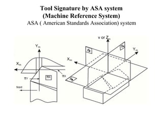
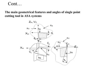
![• πR= Reference plane; plane perpendicular to the velocity vector
• πX= Machine longitudinal plane; plane perpendicular to πRand
taken in the direction of assumed longitudinal feed
• πY= Machine Transverse plane; plane perpendicular to both πR and
πX[This plane is taken in the direction of assumed cross feed]
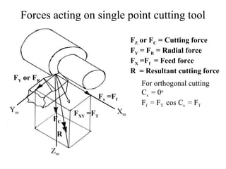
• The axes Xm, Ymand Zmare in the direction of longitudinal feed,
cross feed and cutting velocity (vector) respectively.
Cont…](https://image.slidesharecdn.com/merchantcirclediagram-171218062940/85/Merchant-circle-diagram-6-320.jpg)
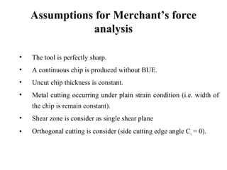
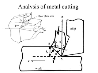
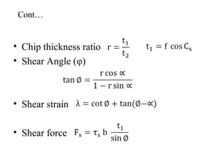
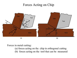
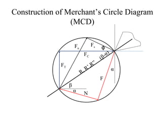
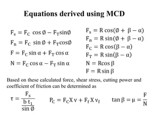


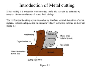
This document provides an overview of mechanics of machining and Merchant's circle diagram (MCD). It introduces metal cutting, tool geometry, assumptions for force analysis, and forces acting on single point cutting tools. Key points include shear plane analysis using rake and shear angles, assumptions of orthogonal cutting and constant chip thickness. Construction of the MCD is described to relate cutting, thrust and feed forces. The MCD allows calculation of shear stress, power and friction coefficient, enabling selection of machine parameters and tool/workpiece design.