Demonstration of Anti Lock Braking System mechanism.
•Download as DOCX, PDF•
0 likes•151 views

Demonstration of Anti Lock Braking System mechanism.

Recommended
More Related Content
What's hot
What's hot (20)
Similar to Demonstration of Anti Lock Braking System mechanism.
Similar to Demonstration of Anti Lock Braking System mechanism. (20)
More from Salman Jailani
More from Salman Jailani (20)
Recently uploaded
Recently uploaded (20)
Demonstration of Anti Lock Braking System mechanism.
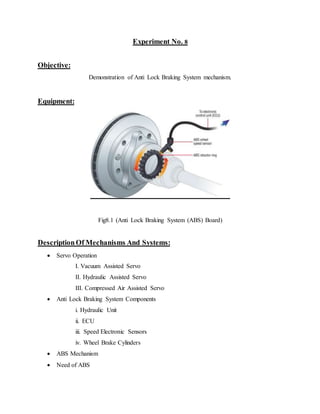
- 1. Experiment No. 8 Objective: Demonstration of Anti Lock Braking System mechanism. Equipment: Fig8.1 (Anti Lock Braking System (ABS) Board) DescriptionOf Mechanisms And Systems: Servo Operation I. Vacuum Assisted Servo II. Hydraulic Assisted Servo III. Compressed Air Assisted Servo Anti Lock Braking System Components i. Hydraulic Unit ii. ECU iii. Speed Electronic Sensors iv. Wheel Brake Cylinders ABS Mechanism Need of ABS
- 2. Difference Between Normal, Power Assisted and ABS Procedure: As the brake pedal depressed it closes the atmospheric valve in servo cylinder and suction valve is opened. A partial vacuum is produced on the one side of the piston while atmosphereexerts pressure on the opposite side. As pressure in the vacuum compartmentbget lower, atmospheric pressure forces the piston along the bore of the cylinder in the direction of vacuum port against the tension of the spring. Piston in servo compartment operate master piston in the fluid filled master cylinder that forces the fluid through the outlet valve and pipe lines to the power pistons which further force the pressurized fluid to wheel cylinders. Speed sensors are available with every wheel that send the signals about wheel skidding to the engine control unit that finally