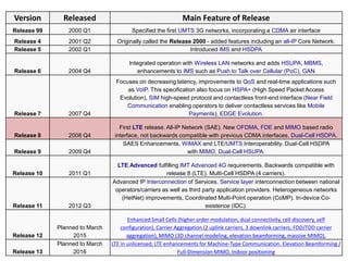
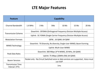
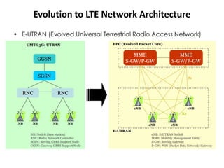
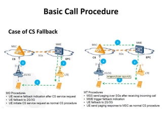
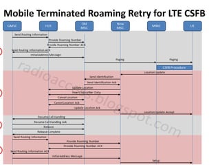
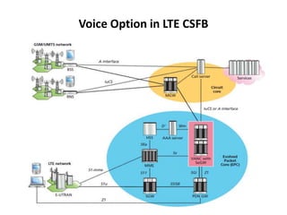
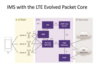
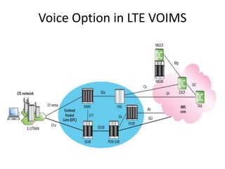
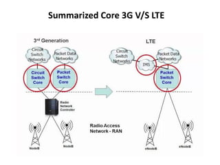
Long Term Evolution (LTE)
Neerav Adhikari
What is LTE ?
• Definition: LTE (Long Term Evolution) is a wireless broadband technology
designed to support roaming Internet access via cell phones and handheld
devices.
• Developed by 3GPP, LTE, Long Term Evolution is the successor to 3G UMTS
and HSPA providing much higher data download speeds and setting the
foundations for LTE Advanced.
• In its first forms it was a 3G or as some would call it a 3.99G technology,
but with further additions the technology fulfilled the requirements for a
4G standard. In this form it was referred to as LTE Advanced.
• There has been a rapid increase in the use of data carried by cellular
services, and this increase will only become larger in what has been
termed the "data explosion". To meet this requirement new technology is
introduced.
• Because LTE offers significant improvements over older cellular
communication standards, some refer to it as a 4G (fourth generation)
technology along with WiMax.
What is LTE cont…
• LTE can theoretically support downloads at 300 Megabits per second
(Mbps) or more based on experimental trials.
• The actual network bandwidth available to an individual LTE subscriber
sharing the service provider's network with other customers is
significantly less.
• LTE is an all IP based network, supporting both IPv4 and IPv6.
• Deployed worldwide and installations are increasing.
• All implementations must meet baseline requirements
◦ Increased Speed
◦ Multiple Antennas (i.e., MIMO)
◦ IP-based network
◦ New air interface: OFDMA (Orthogonal Frequency-Division Multiple Access)
• LTE is always evolving and 3GPP often drops new “releases”
• Originally there was also no basic provision for voice, although Voice over
LTE, VoLTE was added was chosen by GSMA as the standard for this.
• In the interim, techniques including circuit switched fallback(CSFB) or
VoIMS are expected to be used.
Where the Standards of LTE come from ??
• International Telecommunication Union(ITU-T)
– United Nation agency for Information and Telecommunication.
– It has 3 major activates Standardization, Development and Radio
Communication.
– It plays key role in global management of all spectrum.
– How ever there are region stranded bodies in different countries as
well.
What is IMT 2000
• International Mobile Telecommunications-2000 (IMT-2000) is the term used by the
International Telecommunications Union (ITU) for a set of globally harmonized
standards for third generation (3G) mobile telecoms services and equipment.
• 3G services are designed to offer broadband cellular access at speeds of 2Mbps,
which will allow mobile multimedia services to become possible.
• The 3rd Generation Partnership Project (3GPP) unites Seven telecommunications
standard development organizations (ARIB, ATIS, CCSA, ETSI, TSDSI, TTA, TTC),
known as “Organizational Partners” and provides their members with a stable
environment to produce the Reports and Specifications that define 3GPP
technologies.
Where Does LTE Fit In
Market Penetration of LTE (end of 2015)
Version Released Main Feature of Release
Release 99 2000 Q1 Specified the first UMTS 3G networks, incorporating a CDMA air interface
Release 4 2001 Q2 Originally called the Release 2000 - added features including an all-IP Core Network.
Release 5 2002 Q1 Introduced IMS and HSDPA
Release 6 2004 Q4
Integrated operation with Wireless LAN networks and adds HSUPA, MBMS,
enhancements to IMS such as Push to Talk over Cellular (PoC), GAN
Release 7 2007 Q4
Focuses on decreasing latency, improvements to QoS and real-time applications such
as VoIP. This specification also focus on HSPA+ (High Speed Packet Access
Evolution), SIM high-speed protocol and contactless front-end interface (Near Field
Communication enabling operators to deliver contactless services like Mobile
Payments), EDGE Evolution.
Release 8 2008 Q4
First LTE release. All-IP Network (SAE). New OFDMA, FDE and MIMO based radio
interface, not backwards compatible with previous CDMA interfaces. Dual-Cell HSDPA.
Release 9 2009 Q4
SAES Enhancements, WiMAX and LTE/UMTS Interoperability. Dual-Cell HSDPA
with MIMO, Dual-Cell HSUPA.
Release 10 2011 Q1
LTE Advanced fulfilling IMT Advanced 4G requirements. Backwards compatible with
release 8 (LTE). Multi-Cell HSDPA (4 carriers).
Release 11 2012 Q3
Advanced IP Interconnection of Services. Service layer interconnection between national
operators/carriers as well as third party application providers. Heterogeneous networks
(HetNet) improvements, Coordinated Multi-Point operation (CoMP). In-device Co-
existence (IDC).
Release 12
Planned to March
2015
Enhanced Small Cells (higher order modulation, dual connectivity, cell discovery, self
configuration), Carrier Aggregation (2 uplink carriers, 3 downlink carriers, FDD/TDD carrier
aggregation), MIMO (3D channel modeling, elevation beamforming, massive MIMO),
Release 13
Planned to March
2016
LTE in unlicensed, LTE enhancements for Machine-Type Communication. Elevation Beamforming /
Full-Dimension MIMO, Indoor positioning
LTE Major Features
Feature Capability
Channel Bandwidth 1.4 MHz 3 Mz 5Mz 10 Mz 15 Mz 20 Mz
Transmission Scheme
Downlink : OFDMA (Orthogonal Frequency Division Multiple Access)
Uplink : SC-FDMA (Single Carrier Frequency Division Multiple Access)
Modulation Formats QPSK , 16 QAM, 64 QAM
MIMO Technology
Downlink : TX Diversity, Rx diversity, Single-User MIMO, Beam Forming
Uplink: Multi-User MIMO
Peak Data Rates
Downlink: 300 Mbps (4*4 MIMO, 20 MHz, 64 QAM)
Uplink: 75 Mbps (20MHz BW, 64 QAM)
Bearer Services
Packet only - No Circuit Switched voice or data services are supported , Voice must
use VoIP
Transmission Time
Interval (TTI)
1ms
LTE, LTE Advance and IMT (International Mobile
Telecommunications-Advanced) Requirements
Main LTE technologies
• LTE has introduced a number of new technologies when compared to the
previous cellular systems.
• LTE is able to operate more efficiently with respect to the use of spectrum,
and also to provide the much higher data rates that are being required.
• Main LTE technologies used in LTE are:
– OFDM (Orthogonal Frequency Division Multiplex)
– MIMO (Multiple Input Multiple Output)
– SAE (System Architecture Evolution)
Main LTE technologies cont…
• OFDM (Orthogonal Frequency Division Multiplex)
– To overcome the effect of multi path fading problem available in
UMTS, LTE uses Orthogonal Frequency Division Multiplexing (OFDM)
for the downlink
– OFDM is a form of multicarrier modulation. An OFDM signal consists
of a number of closely spaced modulated carriers.
– OFDM technology has been incorporated into LTE because it enables
high data bandwidths to be transmitted efficiently while still providing
a high degree of resilience to reflections and interference.
– OFDM has many advantages including its robustness to multipath
fading and interference.
– OFDM is also a modulation format that is very suitable for carrying
high data rates - one of the key requirements for LTE.
Single Modulated OFDM Sub-Carrier
• Carrier Space creates
orthogonality.
• Phase Noise, timing
decrease orthogonally.
Use of OFDMA
• A scheme used to provide a multiple access capability for applications such as
cellular telecommunications when using OFDM technologies.
• LTE uses the form of OFDM call OFDMA .
• In OFDMA each subcarrier are modulated with different data symbol and last
for relatively longer duration .
• It’s a more advance form of OFDM where the sub-carriers are allocated
different user over time and Frequency.
• Its provides the frequency diversity to slow data rate cases where user might
face problem of narrow band fading.
• Typically the channel pattern per user will frequency hop after each or every
few symbol, which will provide the immunity to the fading versace static
deferment.
SC-FDMA
• In order to reduce the peak to average
power ratio and the efficiency of power
amplifier and save battery life LTE uses
different access mode for uplink i.e SC-
FDMA.
• In SC-FDMA all the subcarriers are
modulated with same data symbol which
lasts for relatively short period of time.
– Eg. As shown in green color data
symbol is modulated with all sub-
carrier for relatively short period of
time.
Multi Antenna Techniques
• The over all goal is to increase the coverage and physical layer capacity.
• Multi Antenna is used because of these three Application
– Path Diversity
• Where one radiated path may be the subject of fading or loss and
another may not.
• Diversity can be introduce in either in transmitter or receiver or both
simultaneously.
– Beam Steering
• Beam steering is about changing the direction of the main lobe of
a radiation pattern so they are directed at the reciver.
• It may be accomplished by switching the antenna elements or by
changing the relative phases of the RF signals driving the elements.
– Spatial Multiplexing
• Separating the Antennas in Space to enable the Spatial Multiplexing.
• The Spatial Multiplexing allows simultaneous transmission of more
than one stream of data in both time and frequency.
Multi Antenna Techniques Cont…
• I and O refers to the into the channel
and out of the channel.
• Single Antenna in the Transmitter and
Single Antenna in the Receiver.
– i.e Single Input Single Output (SISO)
• It is the most basic channel radio
access mode.
• SIMO is the Receive diversity i.e One
transmitter and two or more than to
receiver.
• Eg. The two antennas are used in WiFi
Router to increase the peak data rate.
Multi Antenna Techniques Cont…
• Its an technique in which two antennas
are used at the transmitter end and only
one receive antenna is antenna.
Multi Antenna Techniques Cont…
• MIMO
– Multiple Input Multiple Output can
increase spectral efficiency and
channel capacity.
– Two different data streams that are
show by two different colors are
sent at the same time frequency.
– Two different data stream are
received at two different antenna,
they are then decoded and user
data is retrieved.
– SIMO + MISO ≠ MIMI , as SIMO and
MISO uses only single data stream
but MIMO used two or more then
two data stream.
Evolution to LTE Network Architecture
LTE Network Architecture Cont…
• eNodeB
– eNode B is the RAN node that is responsible for radio transmission to and
reception from UEs in one or more cells.
– The eNode B is connected to Evolved Packet Core(EPC) nodes by means of an
S1 interface. The eNode B may also be connected to its neighbor eNodeBs by
means of the X2 interface.
– As you know, there is no Radio network controller (RNC) in LTE. The
functionality of eNodeB is much enhanced in LTE and it handles the tasks
which were handled by the RNC in the 3G network.
• The following functions are handled by eNode B.
– eNode B controls the radio resources of its own cells.
– The eNode B is responsible for controlling the mobility for terminals in active
state.
– The ciphering of user plane data over the radio interface is terminated in the
eNode B.
– The eNode B handles the physical layer such as, Tx diversity, beamforming
processing, and OFDM modulation. The eNode B also handles power control.
LTE Network Architecture Cont…
• Serving Gateway (S-GW)
– SGW deals with User Plane in LTE ntework.
– It routes and forwards user data packets, while also acting as
the mobility anchor for the user plane during inter-eNB
handovers.
– It manages and stores UE contexts, e.g. parameters of the IP
bearer service, network internal routing information.
– It also performs replication of the user traffic in case of lawful
interception
– Accounting for inter-operator charging.
LTE Network Architecture Cont…
• Mobility Management Entity (MME)
– The MME is responsible for control plane(Signalling) in LTE
network.
– It is responsible for idle mode UE tracking and paging procedure
including retransmissions.
– It is involved in the bearer activation/deactivation process and is
also responsible for choosing the SGW for a UE at the initial
attach and at time of intra-LTE handover involving Core
Network (CN) node relocation.
– It is responsible for authenticating the user (by interacting with
the HSS).
– Lawful interception of signaling is also supported by the MME.
LTE Network Architecture Cont…
• Packet Gateway (P-GW)
– Packet Gateway (PGW) provides connectivity to the UE to external
packet data networks by being the point of exit and entry of traffic for
the UE.
– A UE may have simultaneous connectivity with more than one PGW
for accessing multiple Packet Data Networks.
– It performs policy enforcement, packet filtering for each user, charging
support, lawful Interception and packet screening.
– Another key role of the PDN GW is to act as the anchor for mobility
between 3GPP and non-3GPP technologies such as WiMAX and 3GPP2
(CDMA 1X and EvDO).
LTE Network Architecture Cont…
• HSS and AAA
– Like HLR in 2G/3G HSS is responsible for storing all the subscriber
information.
– The MME communicates with HSS for Aunthetication which inturn
communicates with AAA server for Authenticatinon,Authorization and
Accunting of UE in the LTE network.
Voice Deployment Options of LTE
• Circuit Switched Fall Back (CS Fallback)
– CS fallback supports voice services for LTE by reusing the
GSM/UMTS network
– Mobile devices, normally Latch on the LTE network for data
services, are forced to fall back to the legacy network when
subscribers want to use CS services, such as voice
– CS fallback-enabled device must register on both the LTE and
GSM/UMTS networks
– Terminals used for CS fallback must be able access the LTE as
well as the GSM/UMTS networks.
SGs Associated Location Update
 MME find CSFB VMSC number
according to TA-LAI-MSC mapping
 After successful SGs location
update, VMSC get ready for later
CSFB procedure
SGs Associated Location Update
Cont…
Basic Call Procedure
Case of CS Fallback
Mobile Terminated Roaming in LTE for
CSFB
 Typically occurs on the borders of Location Areas (LA) and
Tracking Areas (TA) or MSC Border
 In order to avoid MT call failures, operators must implement
either
 MTRR (Mobile Terminating Roaming Retry) or
 MTRF (Mobile Terminating Roaming Forwarding)
Mobile Terminated Roaming Forwarding for CSFB
Mobile Terminated Roaming Retry for LTE CSFB
Voice Option in LTE CSFB
– Digitized voice-band audio transmitted as IP packets and
demodulated into voice-band audio
– GSM/UMTS CS service continuity is implemented with the
aid of IMS Centralized Services (ICS) and SRVCC
– VoIMS-enabled UEs, whether using the LTE or UMTS PS
access networks, always register on the IMS network and
receive all data and voice services from IMS
– When a mobile device originates or terminates a voice
session on the IMS network using LTE or UMTS PS access,
the session is set up according the standard originating or
terminating IMS procedure
Voice Over IP Multimedia Subsystem
(VoIMS)
IMS with the LTE Evolved Packet Core
VOIMS
• User Entity (UE)
– UE in IMS contains a Universal Integrated Circuit Card
(UICC) and a Session Initiation Protocol User Agent (SIP
UA).
– SIP Protocol is used for voice service in Pure IMS Network (
not CS Network).
• Policy and Charging Rules Function (PCRF)
– The PCRF provides real-time determination of what types
of traffic are allowed under what conditions, and also
determines how to charge for this traffic use(for billing
purposes).
– If a user attempts to launch a VoLTE call (and is authorized
to do so), the PCRF will initiate the setup of the dedicated
bearer.
Voice Option in LTE VOIMS
Summarized Core 3G V/S LTE
LTE Frequency Band
E-UTRA Duplex- ƒ
Common
name
Uplink (UL)
Downlink
(DL) Duplex Channel
Band Mode (MHz) BS receive BS transmit spacing bandwidths
UE transmit
(MHz)
UE receive
(MHz) (MHz) (MHz)
1 FDD 2100 IMT 1920 – 1980 2110 – 2170 190 5, 10, 15, 20
2 FDD 1900
PCS blocks
A-F 1850 – 1910 1930 – 1990 80
1.4, 3, 5, 10,
15, 20
3 FDD 1800 DCS 1710 – 1785 1805 – 1880 95
1.4, 3, 5, 10,
15, 20
4 FDD 1700
AWS blocks
A-F (AWS-1) 1710 – 1755 2110 – 2155 400
1.4, 3, 5, 10,
15, 20
5 FDD 850 CLR 824 – 849 869 – 894 45 1.4, 3, 5, 10
6 FDD 850
Japan UMTS
800 (obsolet
e) 830 – 840 875 – 885 45 5, 10
7 FDD 2600 IMT-E 2500 – 2570 2620 – 2690 120 5, 10, 15, 20
8 FDD 900 E-GSM 880 – 915 925 – 960 45 1.4, 3, 5, 10
What after 4G ?
Evolution of Wireless Communication Standards
Quick Comparison Chart
Evolution towards 5G
• 5G is still “undefined”
• Expected to be a combination of various elements
towards a more efficient, fast, converged network
• Spectral efficiency significantly enhanced compared
to 4G
• Signalling efficiency enhanced
• 1 gigabit per second simultaneously to many
workers on the same office floor
• Latency reduced significantly compared to LTE
Some of 5G Components
Massive MIMO
Higher order modulation (e.g., 256QAM)
Flexible spectrum usage (in bands up to order
of 100GHz)
Multi-hop/Relays
Device to Device
Reference
• http://radioaccess.blogspot.com/2013/01/mo
bile-terminated-roaming-forwarding.html
• https://en.wikipedia.org/wiki/LTE_(telecomm
unication)
LTE Basic

LTE Basic

  • 1.
    Long Term Evolution(LTE) Neerav Adhikari
  • 2.
    What is LTE? • Definition: LTE (Long Term Evolution) is a wireless broadband technology designed to support roaming Internet access via cell phones and handheld devices. • Developed by 3GPP, LTE, Long Term Evolution is the successor to 3G UMTS and HSPA providing much higher data download speeds and setting the foundations for LTE Advanced. • In its first forms it was a 3G or as some would call it a 3.99G technology, but with further additions the technology fulfilled the requirements for a 4G standard. In this form it was referred to as LTE Advanced. • There has been a rapid increase in the use of data carried by cellular services, and this increase will only become larger in what has been termed the "data explosion". To meet this requirement new technology is introduced. • Because LTE offers significant improvements over older cellular communication standards, some refer to it as a 4G (fourth generation) technology along with WiMax.
  • 3.
    What is LTEcont… • LTE can theoretically support downloads at 300 Megabits per second (Mbps) or more based on experimental trials. • The actual network bandwidth available to an individual LTE subscriber sharing the service provider's network with other customers is significantly less. • LTE is an all IP based network, supporting both IPv4 and IPv6. • Deployed worldwide and installations are increasing. • All implementations must meet baseline requirements ◦ Increased Speed ◦ Multiple Antennas (i.e., MIMO) ◦ IP-based network ◦ New air interface: OFDMA (Orthogonal Frequency-Division Multiple Access) • LTE is always evolving and 3GPP often drops new “releases” • Originally there was also no basic provision for voice, although Voice over LTE, VoLTE was added was chosen by GSMA as the standard for this. • In the interim, techniques including circuit switched fallback(CSFB) or VoIMS are expected to be used.
  • 4.
    Where the Standardsof LTE come from ?? • International Telecommunication Union(ITU-T) – United Nation agency for Information and Telecommunication. – It has 3 major activates Standardization, Development and Radio Communication. – It plays key role in global management of all spectrum. – How ever there are region stranded bodies in different countries as well.
  • 5.
    What is IMT2000 • International Mobile Telecommunications-2000 (IMT-2000) is the term used by the International Telecommunications Union (ITU) for a set of globally harmonized standards for third generation (3G) mobile telecoms services and equipment. • 3G services are designed to offer broadband cellular access at speeds of 2Mbps, which will allow mobile multimedia services to become possible. • The 3rd Generation Partnership Project (3GPP) unites Seven telecommunications standard development organizations (ARIB, ATIS, CCSA, ETSI, TSDSI, TTA, TTC), known as “Organizational Partners” and provides their members with a stable environment to produce the Reports and Specifications that define 3GPP technologies.
  • 6.
  • 7.
    Market Penetration ofLTE (end of 2015)
  • 8.
    Version Released MainFeature of Release Release 99 2000 Q1 Specified the first UMTS 3G networks, incorporating a CDMA air interface Release 4 2001 Q2 Originally called the Release 2000 - added features including an all-IP Core Network. Release 5 2002 Q1 Introduced IMS and HSDPA Release 6 2004 Q4 Integrated operation with Wireless LAN networks and adds HSUPA, MBMS, enhancements to IMS such as Push to Talk over Cellular (PoC), GAN Release 7 2007 Q4 Focuses on decreasing latency, improvements to QoS and real-time applications such as VoIP. This specification also focus on HSPA+ (High Speed Packet Access Evolution), SIM high-speed protocol and contactless front-end interface (Near Field Communication enabling operators to deliver contactless services like Mobile Payments), EDGE Evolution. Release 8 2008 Q4 First LTE release. All-IP Network (SAE). New OFDMA, FDE and MIMO based radio interface, not backwards compatible with previous CDMA interfaces. Dual-Cell HSDPA. Release 9 2009 Q4 SAES Enhancements, WiMAX and LTE/UMTS Interoperability. Dual-Cell HSDPA with MIMO, Dual-Cell HSUPA. Release 10 2011 Q1 LTE Advanced fulfilling IMT Advanced 4G requirements. Backwards compatible with release 8 (LTE). Multi-Cell HSDPA (4 carriers). Release 11 2012 Q3 Advanced IP Interconnection of Services. Service layer interconnection between national operators/carriers as well as third party application providers. Heterogeneous networks (HetNet) improvements, Coordinated Multi-Point operation (CoMP). In-device Co- existence (IDC). Release 12 Planned to March 2015 Enhanced Small Cells (higher order modulation, dual connectivity, cell discovery, self configuration), Carrier Aggregation (2 uplink carriers, 3 downlink carriers, FDD/TDD carrier aggregation), MIMO (3D channel modeling, elevation beamforming, massive MIMO), Release 13 Planned to March 2016 LTE in unlicensed, LTE enhancements for Machine-Type Communication. Elevation Beamforming / Full-Dimension MIMO, Indoor positioning
  • 9.
    LTE Major Features FeatureCapability Channel Bandwidth 1.4 MHz 3 Mz 5Mz 10 Mz 15 Mz 20 Mz Transmission Scheme Downlink : OFDMA (Orthogonal Frequency Division Multiple Access) Uplink : SC-FDMA (Single Carrier Frequency Division Multiple Access) Modulation Formats QPSK , 16 QAM, 64 QAM MIMO Technology Downlink : TX Diversity, Rx diversity, Single-User MIMO, Beam Forming Uplink: Multi-User MIMO Peak Data Rates Downlink: 300 Mbps (4*4 MIMO, 20 MHz, 64 QAM) Uplink: 75 Mbps (20MHz BW, 64 QAM) Bearer Services Packet only - No Circuit Switched voice or data services are supported , Voice must use VoIP Transmission Time Interval (TTI) 1ms
  • 10.
    LTE, LTE Advanceand IMT (International Mobile Telecommunications-Advanced) Requirements
  • 11.
    Main LTE technologies •LTE has introduced a number of new technologies when compared to the previous cellular systems. • LTE is able to operate more efficiently with respect to the use of spectrum, and also to provide the much higher data rates that are being required. • Main LTE technologies used in LTE are: – OFDM (Orthogonal Frequency Division Multiplex) – MIMO (Multiple Input Multiple Output) – SAE (System Architecture Evolution)
  • 12.
    Main LTE technologiescont… • OFDM (Orthogonal Frequency Division Multiplex) – To overcome the effect of multi path fading problem available in UMTS, LTE uses Orthogonal Frequency Division Multiplexing (OFDM) for the downlink – OFDM is a form of multicarrier modulation. An OFDM signal consists of a number of closely spaced modulated carriers. – OFDM technology has been incorporated into LTE because it enables high data bandwidths to be transmitted efficiently while still providing a high degree of resilience to reflections and interference. – OFDM has many advantages including its robustness to multipath fading and interference. – OFDM is also a modulation format that is very suitable for carrying high data rates - one of the key requirements for LTE.
  • 13.
    Single Modulated OFDMSub-Carrier • Carrier Space creates orthogonality. • Phase Noise, timing decrease orthogonally.
  • 14.
    Use of OFDMA •A scheme used to provide a multiple access capability for applications such as cellular telecommunications when using OFDM technologies. • LTE uses the form of OFDM call OFDMA . • In OFDMA each subcarrier are modulated with different data symbol and last for relatively longer duration . • It’s a more advance form of OFDM where the sub-carriers are allocated different user over time and Frequency. • Its provides the frequency diversity to slow data rate cases where user might face problem of narrow band fading. • Typically the channel pattern per user will frequency hop after each or every few symbol, which will provide the immunity to the fading versace static deferment.
  • 15.
    SC-FDMA • In orderto reduce the peak to average power ratio and the efficiency of power amplifier and save battery life LTE uses different access mode for uplink i.e SC- FDMA. • In SC-FDMA all the subcarriers are modulated with same data symbol which lasts for relatively short period of time. – Eg. As shown in green color data symbol is modulated with all sub- carrier for relatively short period of time.
  • 16.
    Multi Antenna Techniques •The over all goal is to increase the coverage and physical layer capacity. • Multi Antenna is used because of these three Application – Path Diversity • Where one radiated path may be the subject of fading or loss and another may not. • Diversity can be introduce in either in transmitter or receiver or both simultaneously. – Beam Steering • Beam steering is about changing the direction of the main lobe of a radiation pattern so they are directed at the reciver. • It may be accomplished by switching the antenna elements or by changing the relative phases of the RF signals driving the elements. – Spatial Multiplexing • Separating the Antennas in Space to enable the Spatial Multiplexing. • The Spatial Multiplexing allows simultaneous transmission of more than one stream of data in both time and frequency.
  • 17.
    Multi Antenna TechniquesCont… • I and O refers to the into the channel and out of the channel. • Single Antenna in the Transmitter and Single Antenna in the Receiver. – i.e Single Input Single Output (SISO) • It is the most basic channel radio access mode. • SIMO is the Receive diversity i.e One transmitter and two or more than to receiver. • Eg. The two antennas are used in WiFi Router to increase the peak data rate.
  • 18.
    Multi Antenna TechniquesCont… • Its an technique in which two antennas are used at the transmitter end and only one receive antenna is antenna.
  • 19.
    Multi Antenna TechniquesCont… • MIMO – Multiple Input Multiple Output can increase spectral efficiency and channel capacity. – Two different data streams that are show by two different colors are sent at the same time frequency. – Two different data stream are received at two different antenna, they are then decoded and user data is retrieved. – SIMO + MISO ≠ MIMI , as SIMO and MISO uses only single data stream but MIMO used two or more then two data stream.
  • 21.
    Evolution to LTENetwork Architecture
  • 22.
    LTE Network ArchitectureCont… • eNodeB – eNode B is the RAN node that is responsible for radio transmission to and reception from UEs in one or more cells. – The eNode B is connected to Evolved Packet Core(EPC) nodes by means of an S1 interface. The eNode B may also be connected to its neighbor eNodeBs by means of the X2 interface. – As you know, there is no Radio network controller (RNC) in LTE. The functionality of eNodeB is much enhanced in LTE and it handles the tasks which were handled by the RNC in the 3G network. • The following functions are handled by eNode B. – eNode B controls the radio resources of its own cells. – The eNode B is responsible for controlling the mobility for terminals in active state. – The ciphering of user plane data over the radio interface is terminated in the eNode B. – The eNode B handles the physical layer such as, Tx diversity, beamforming processing, and OFDM modulation. The eNode B also handles power control.
  • 23.
    LTE Network ArchitectureCont… • Serving Gateway (S-GW) – SGW deals with User Plane in LTE ntework. – It routes and forwards user data packets, while also acting as the mobility anchor for the user plane during inter-eNB handovers. – It manages and stores UE contexts, e.g. parameters of the IP bearer service, network internal routing information. – It also performs replication of the user traffic in case of lawful interception – Accounting for inter-operator charging.
  • 24.
    LTE Network ArchitectureCont… • Mobility Management Entity (MME) – The MME is responsible for control plane(Signalling) in LTE network. – It is responsible for idle mode UE tracking and paging procedure including retransmissions. – It is involved in the bearer activation/deactivation process and is also responsible for choosing the SGW for a UE at the initial attach and at time of intra-LTE handover involving Core Network (CN) node relocation. – It is responsible for authenticating the user (by interacting with the HSS). – Lawful interception of signaling is also supported by the MME.
  • 25.
    LTE Network ArchitectureCont… • Packet Gateway (P-GW) – Packet Gateway (PGW) provides connectivity to the UE to external packet data networks by being the point of exit and entry of traffic for the UE. – A UE may have simultaneous connectivity with more than one PGW for accessing multiple Packet Data Networks. – It performs policy enforcement, packet filtering for each user, charging support, lawful Interception and packet screening. – Another key role of the PDN GW is to act as the anchor for mobility between 3GPP and non-3GPP technologies such as WiMAX and 3GPP2 (CDMA 1X and EvDO).
  • 26.
    LTE Network ArchitectureCont… • HSS and AAA – Like HLR in 2G/3G HSS is responsible for storing all the subscriber information. – The MME communicates with HSS for Aunthetication which inturn communicates with AAA server for Authenticatinon,Authorization and Accunting of UE in the LTE network.
  • 27.
  • 28.
    Voice Deployment Optionsof LTE • Circuit Switched Fall Back (CS Fallback) – CS fallback supports voice services for LTE by reusing the GSM/UMTS network – Mobile devices, normally Latch on the LTE network for data services, are forced to fall back to the legacy network when subscribers want to use CS services, such as voice – CS fallback-enabled device must register on both the LTE and GSM/UMTS networks – Terminals used for CS fallback must be able access the LTE as well as the GSM/UMTS networks.
  • 29.
    SGs Associated LocationUpdate  MME find CSFB VMSC number according to TA-LAI-MSC mapping  After successful SGs location update, VMSC get ready for later CSFB procedure
  • 30.
  • 31.
  • 32.
    Mobile Terminated Roamingin LTE for CSFB  Typically occurs on the borders of Location Areas (LA) and Tracking Areas (TA) or MSC Border  In order to avoid MT call failures, operators must implement either  MTRR (Mobile Terminating Roaming Retry) or  MTRF (Mobile Terminating Roaming Forwarding)
  • 33.
    Mobile Terminated RoamingForwarding for CSFB
  • 34.
    Mobile Terminated RoamingRetry for LTE CSFB
  • 35.
  • 36.
    – Digitized voice-bandaudio transmitted as IP packets and demodulated into voice-band audio – GSM/UMTS CS service continuity is implemented with the aid of IMS Centralized Services (ICS) and SRVCC – VoIMS-enabled UEs, whether using the LTE or UMTS PS access networks, always register on the IMS network and receive all data and voice services from IMS – When a mobile device originates or terminates a voice session on the IMS network using LTE or UMTS PS access, the session is set up according the standard originating or terminating IMS procedure Voice Over IP Multimedia Subsystem (VoIMS)
  • 37.
    IMS with theLTE Evolved Packet Core
  • 38.
    VOIMS • User Entity(UE) – UE in IMS contains a Universal Integrated Circuit Card (UICC) and a Session Initiation Protocol User Agent (SIP UA). – SIP Protocol is used for voice service in Pure IMS Network ( not CS Network). • Policy and Charging Rules Function (PCRF) – The PCRF provides real-time determination of what types of traffic are allowed under what conditions, and also determines how to charge for this traffic use(for billing purposes). – If a user attempts to launch a VoLTE call (and is authorized to do so), the PCRF will initiate the setup of the dedicated bearer.
  • 39.
    Voice Option inLTE VOIMS
  • 40.
  • 41.
    LTE Frequency Band E-UTRADuplex- ƒ Common name Uplink (UL) Downlink (DL) Duplex Channel Band Mode (MHz) BS receive BS transmit spacing bandwidths UE transmit (MHz) UE receive (MHz) (MHz) (MHz) 1 FDD 2100 IMT 1920 – 1980 2110 – 2170 190 5, 10, 15, 20 2 FDD 1900 PCS blocks A-F 1850 – 1910 1930 – 1990 80 1.4, 3, 5, 10, 15, 20 3 FDD 1800 DCS 1710 – 1785 1805 – 1880 95 1.4, 3, 5, 10, 15, 20 4 FDD 1700 AWS blocks A-F (AWS-1) 1710 – 1755 2110 – 2155 400 1.4, 3, 5, 10, 15, 20 5 FDD 850 CLR 824 – 849 869 – 894 45 1.4, 3, 5, 10 6 FDD 850 Japan UMTS 800 (obsolet e) 830 – 840 875 – 885 45 5, 10 7 FDD 2600 IMT-E 2500 – 2570 2620 – 2690 120 5, 10, 15, 20 8 FDD 900 E-GSM 880 – 915 925 – 960 45 1.4, 3, 5, 10
  • 42.
    What after 4G? Evolution of Wireless Communication Standards
  • 43.
  • 44.
    Evolution towards 5G •5G is still “undefined” • Expected to be a combination of various elements towards a more efficient, fast, converged network • Spectral efficiency significantly enhanced compared to 4G • Signalling efficiency enhanced • 1 gigabit per second simultaneously to many workers on the same office floor • Latency reduced significantly compared to LTE
  • 45.
    Some of 5GComponents Massive MIMO Higher order modulation (e.g., 256QAM) Flexible spectrum usage (in bands up to order of 100GHz) Multi-hop/Relays Device to Device
  • 46.