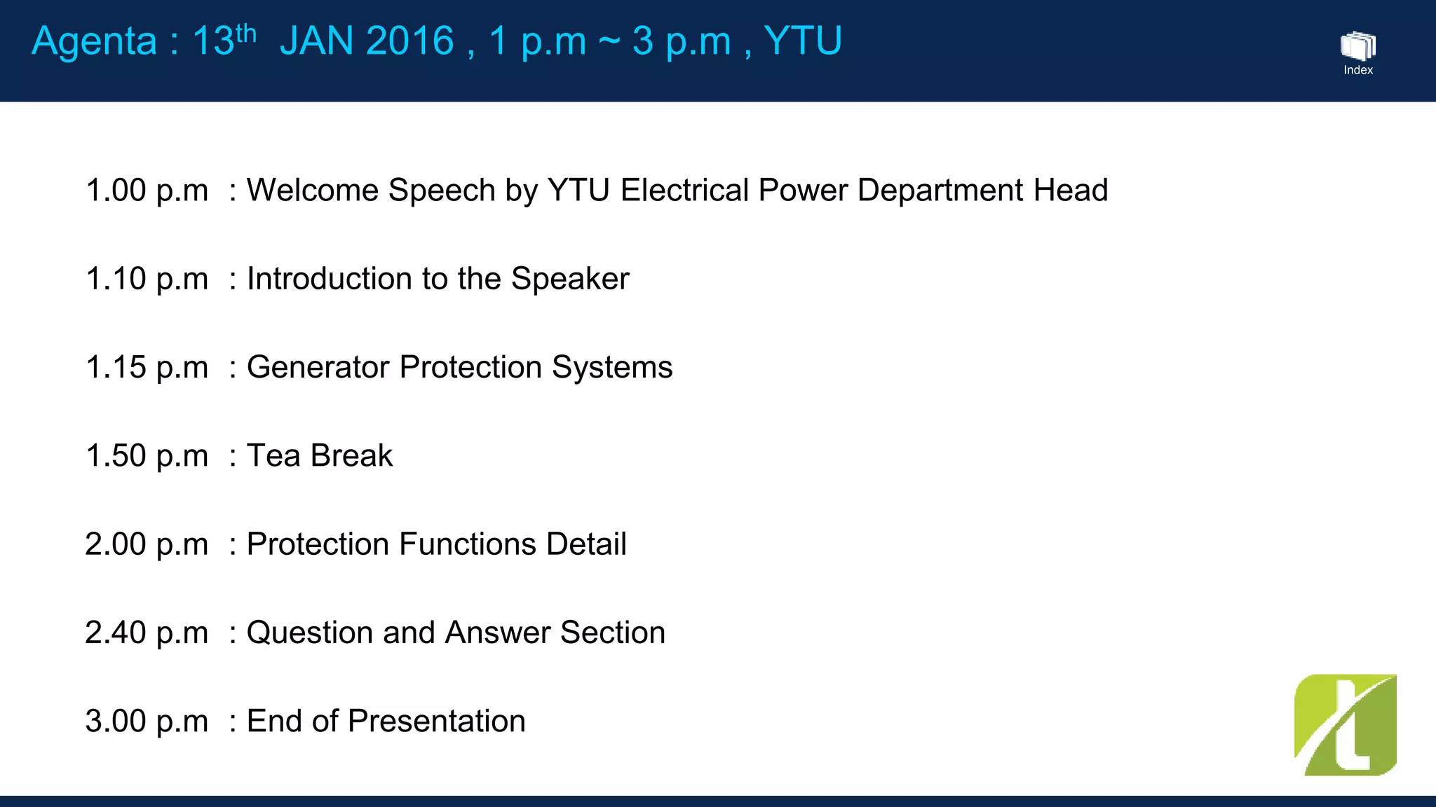
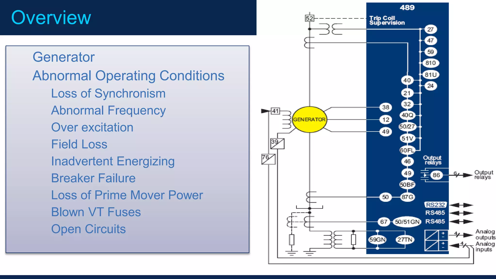
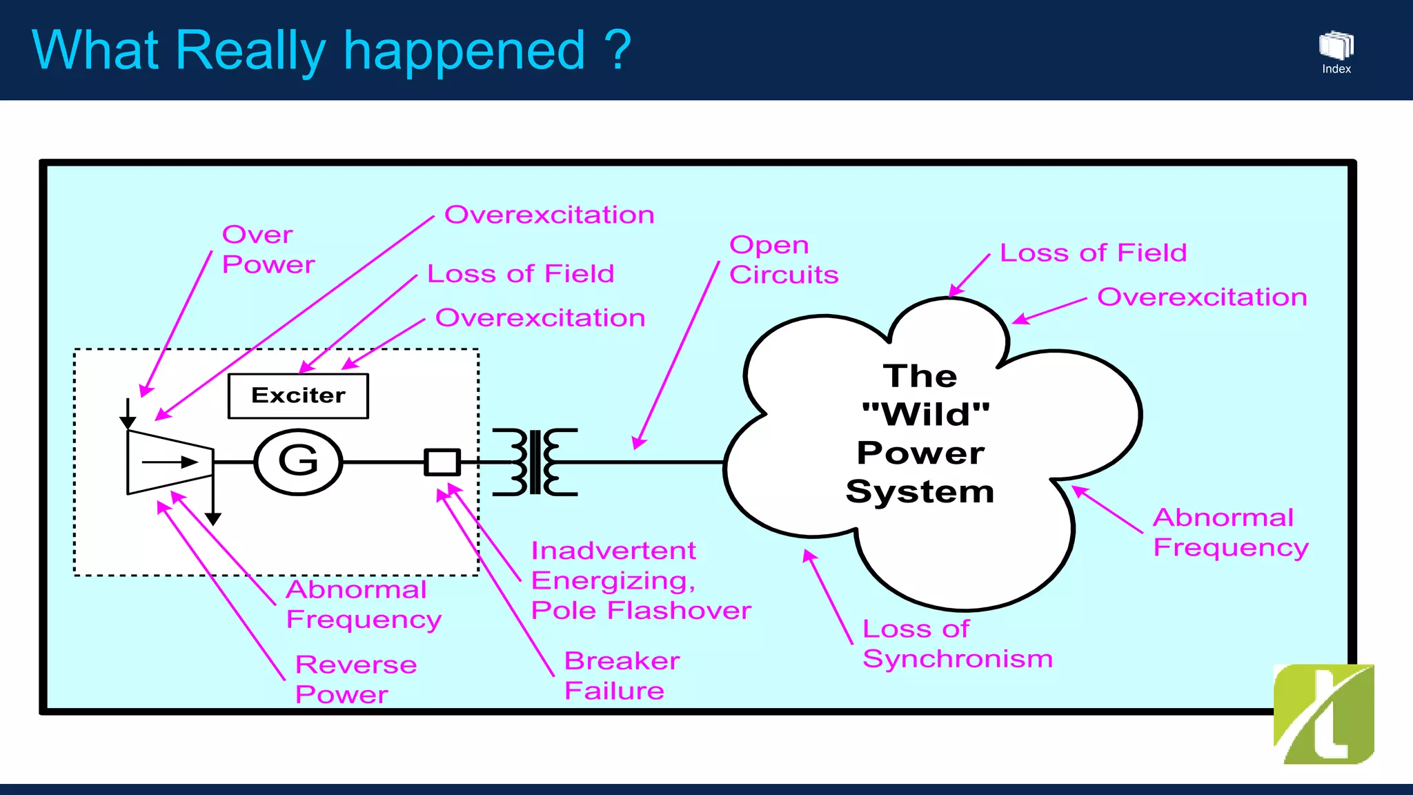
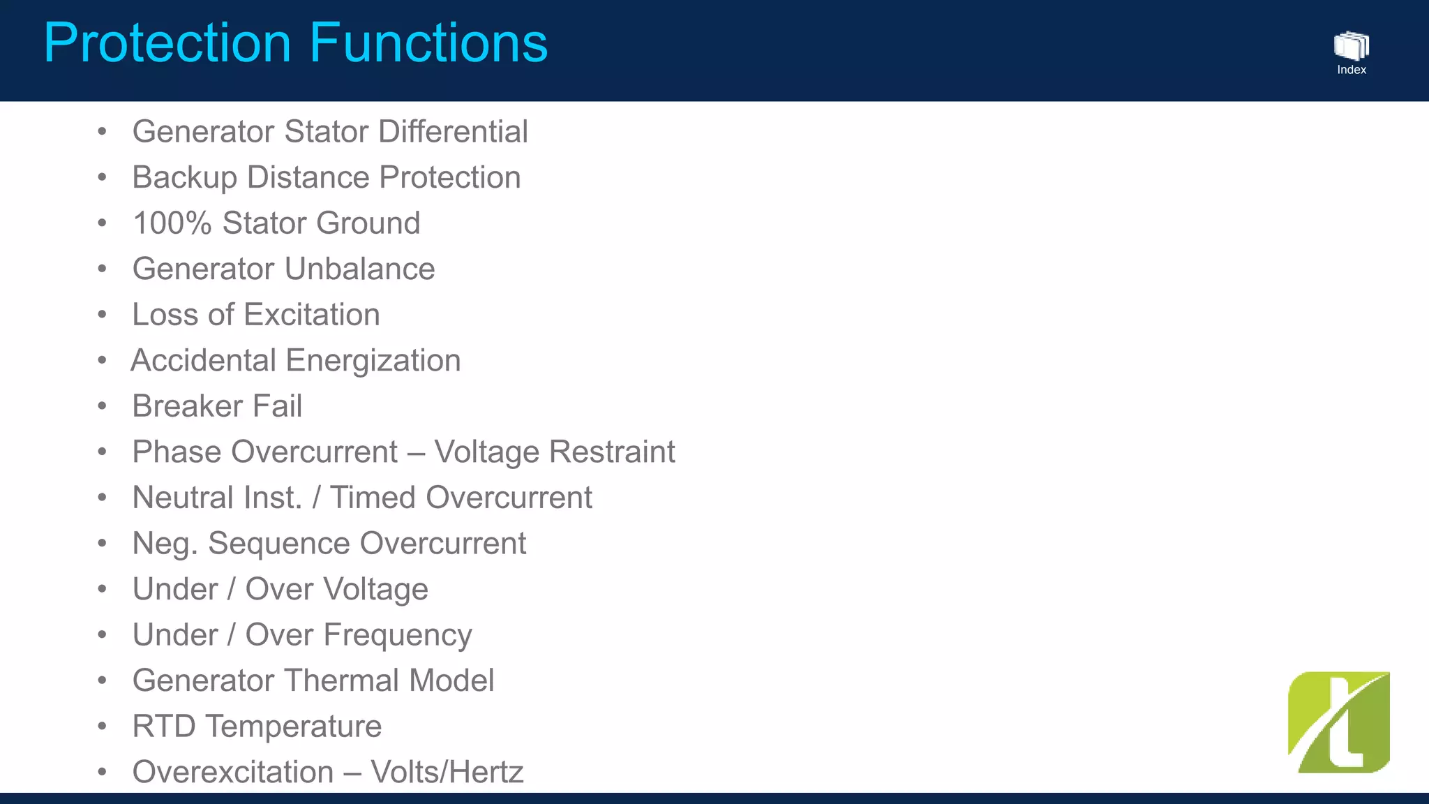
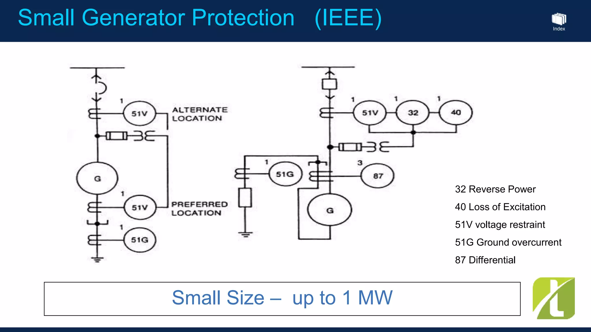
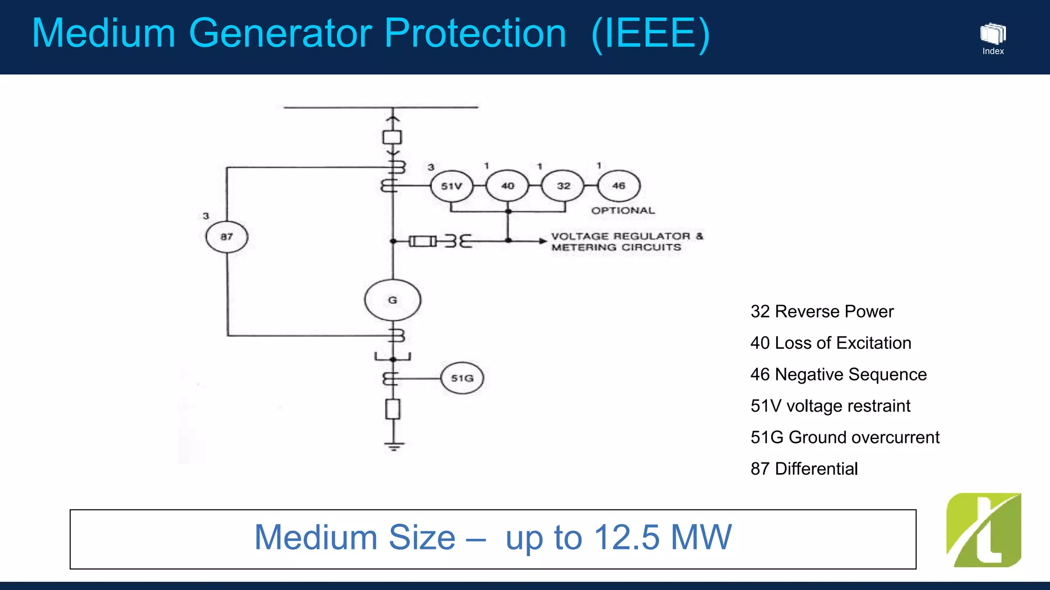
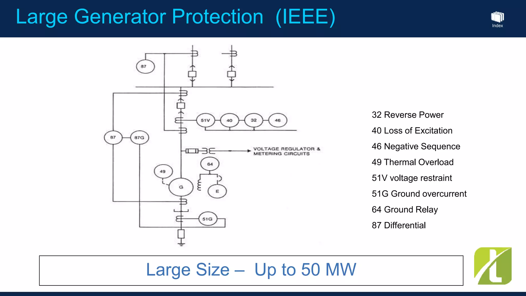
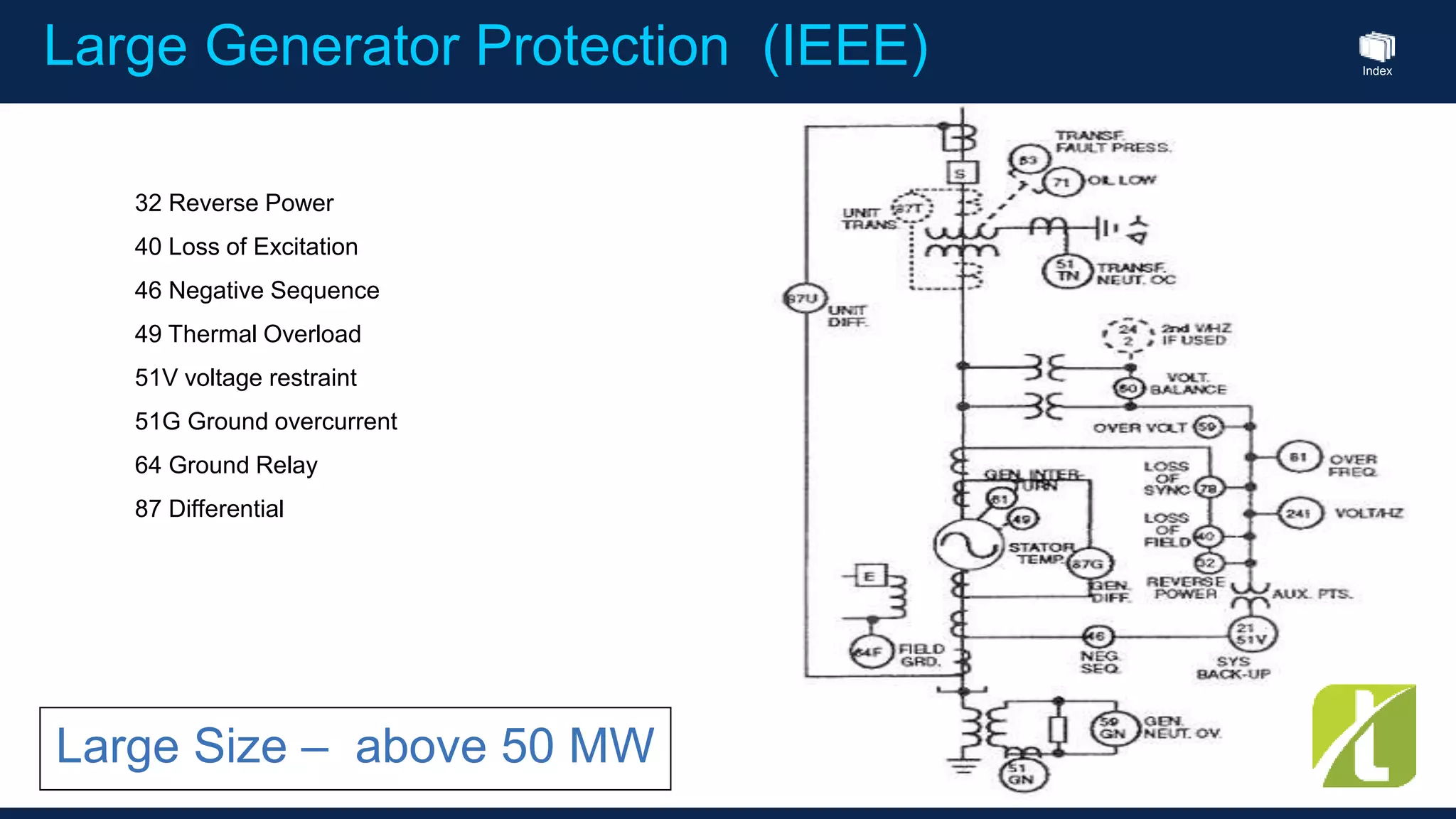
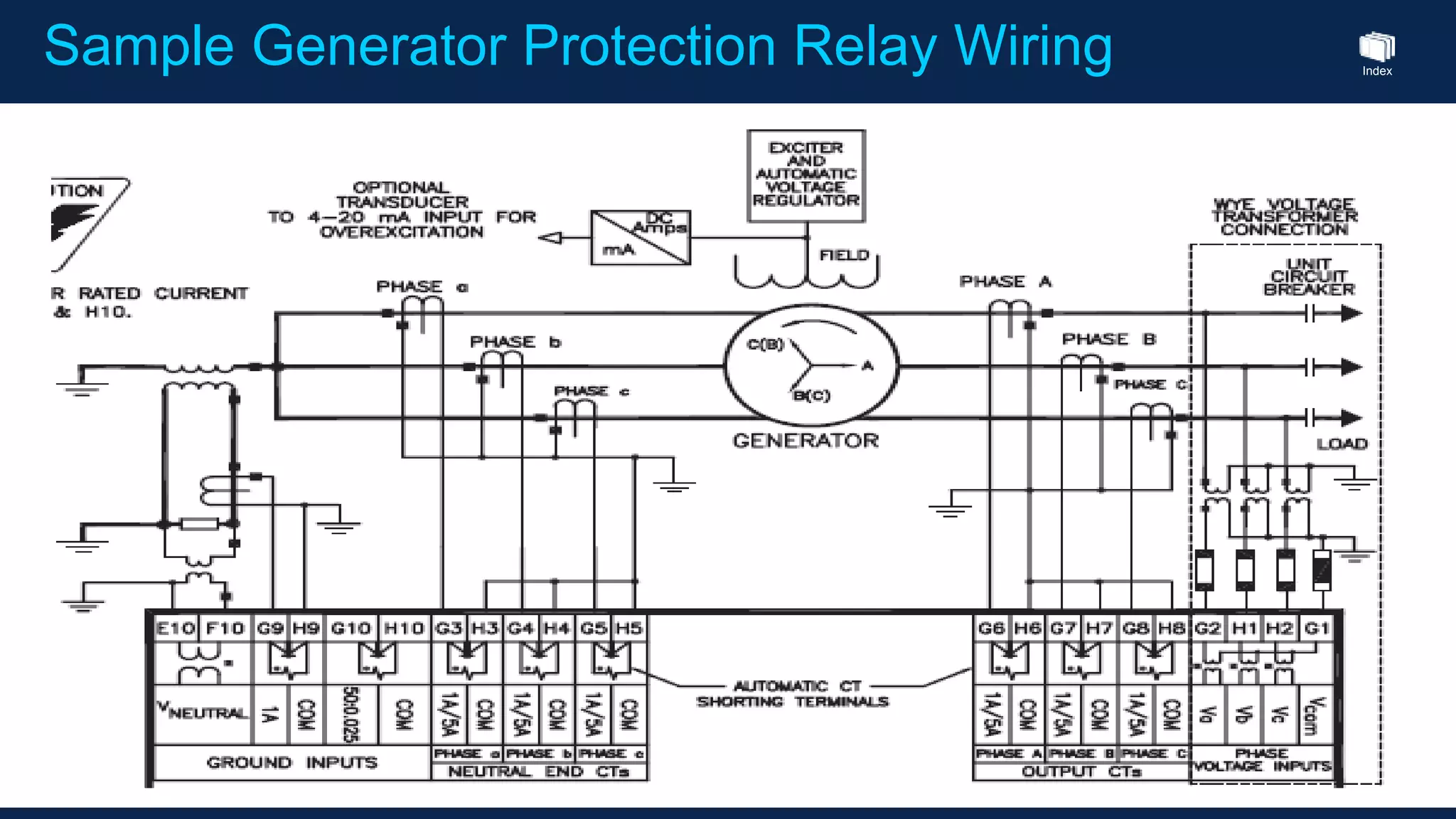
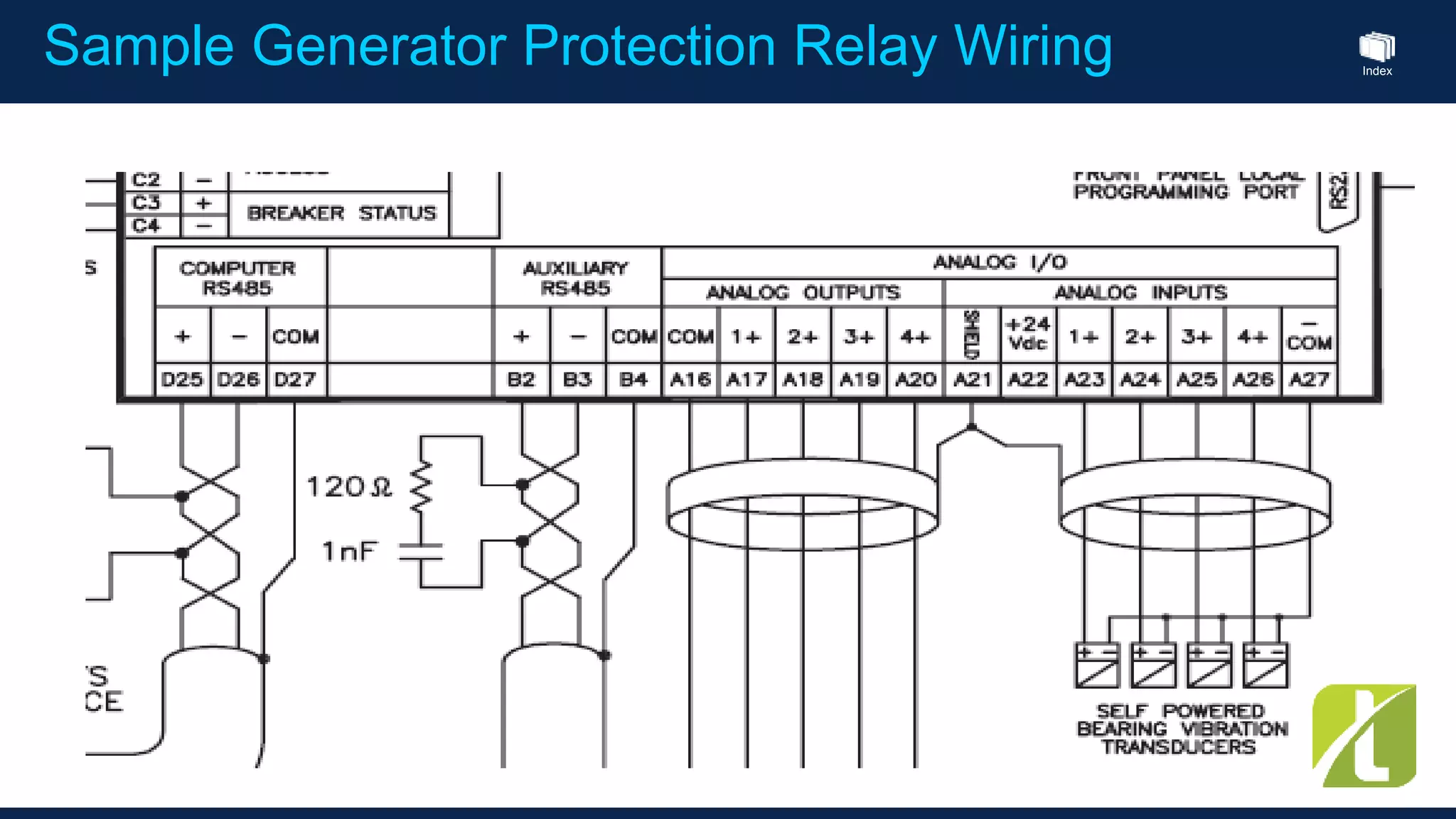
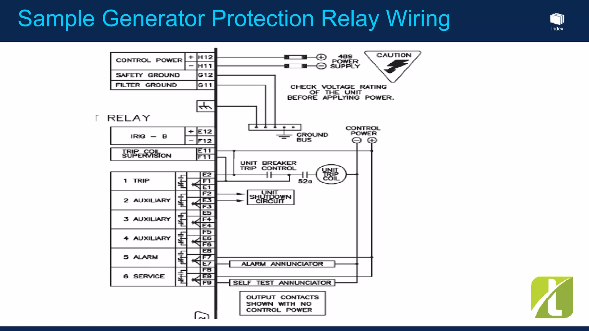
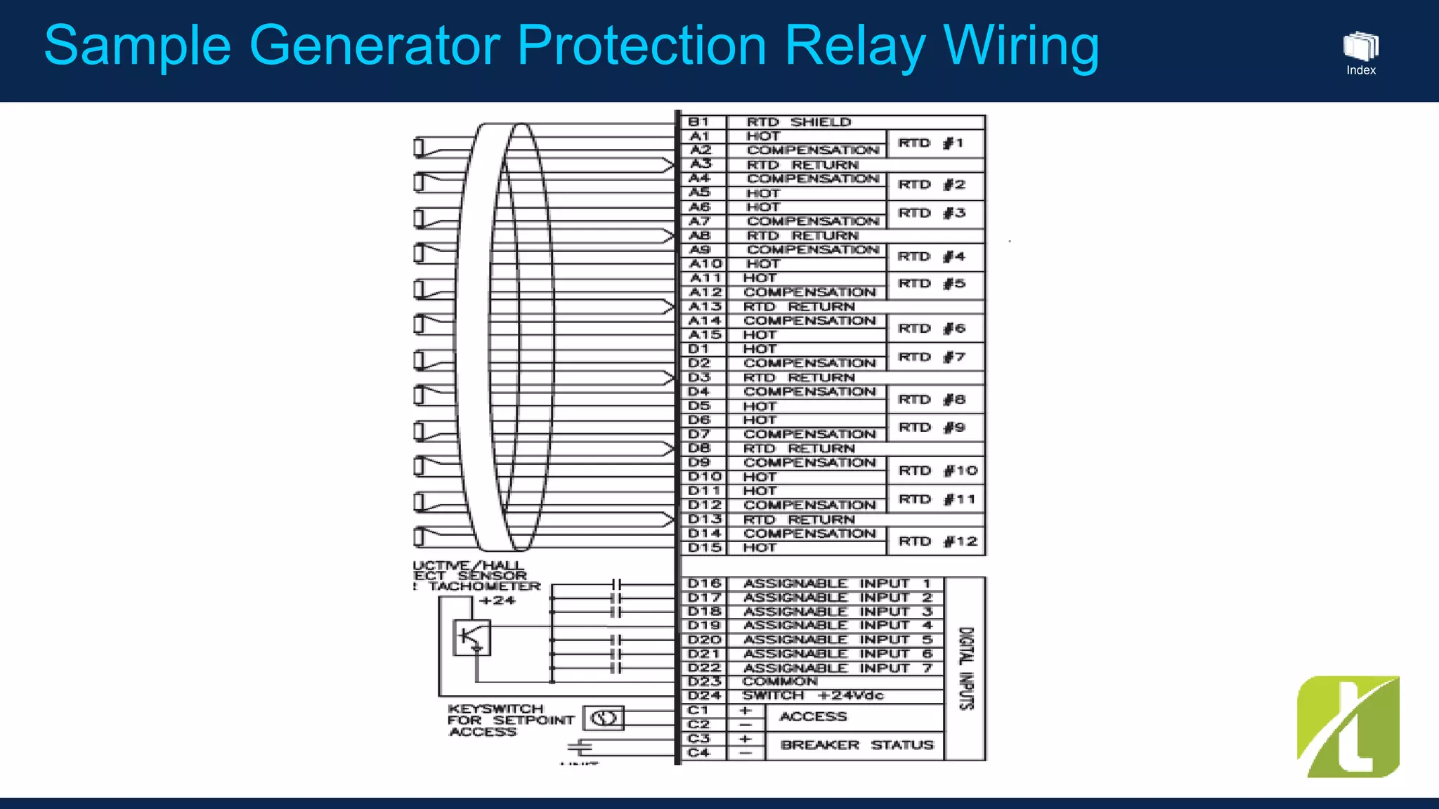
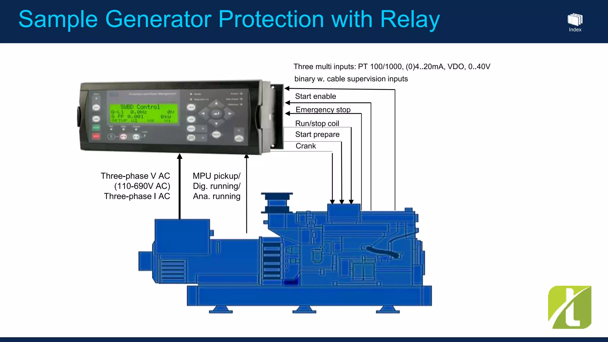
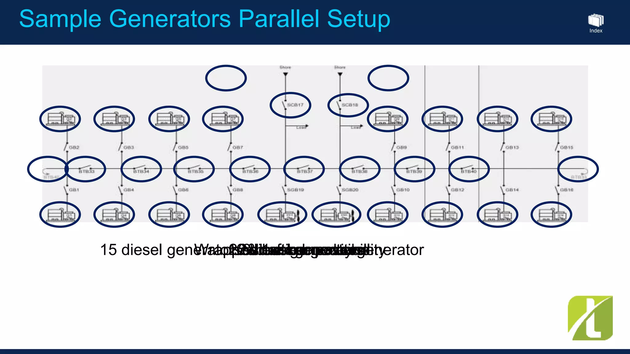
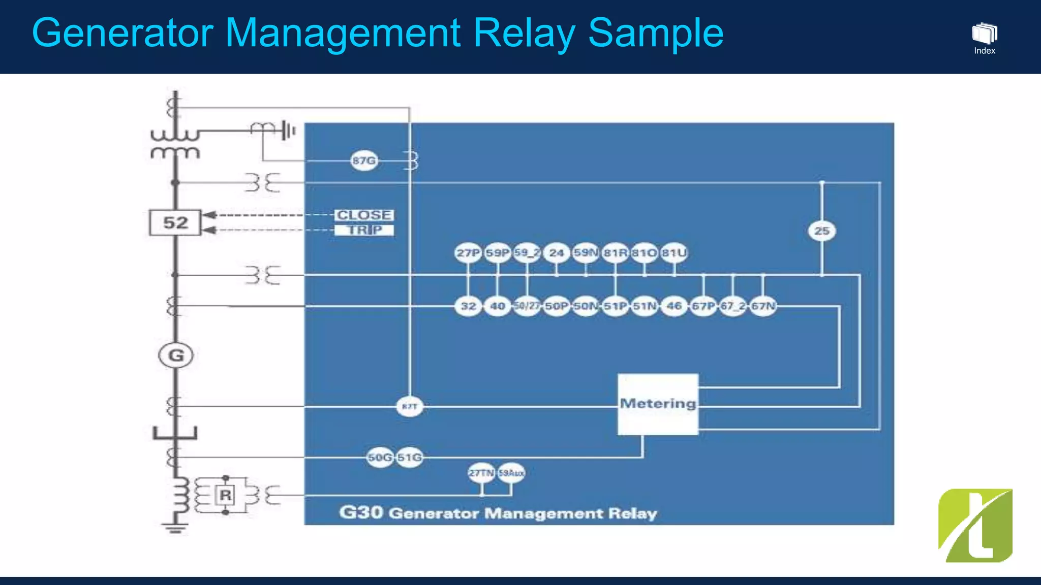
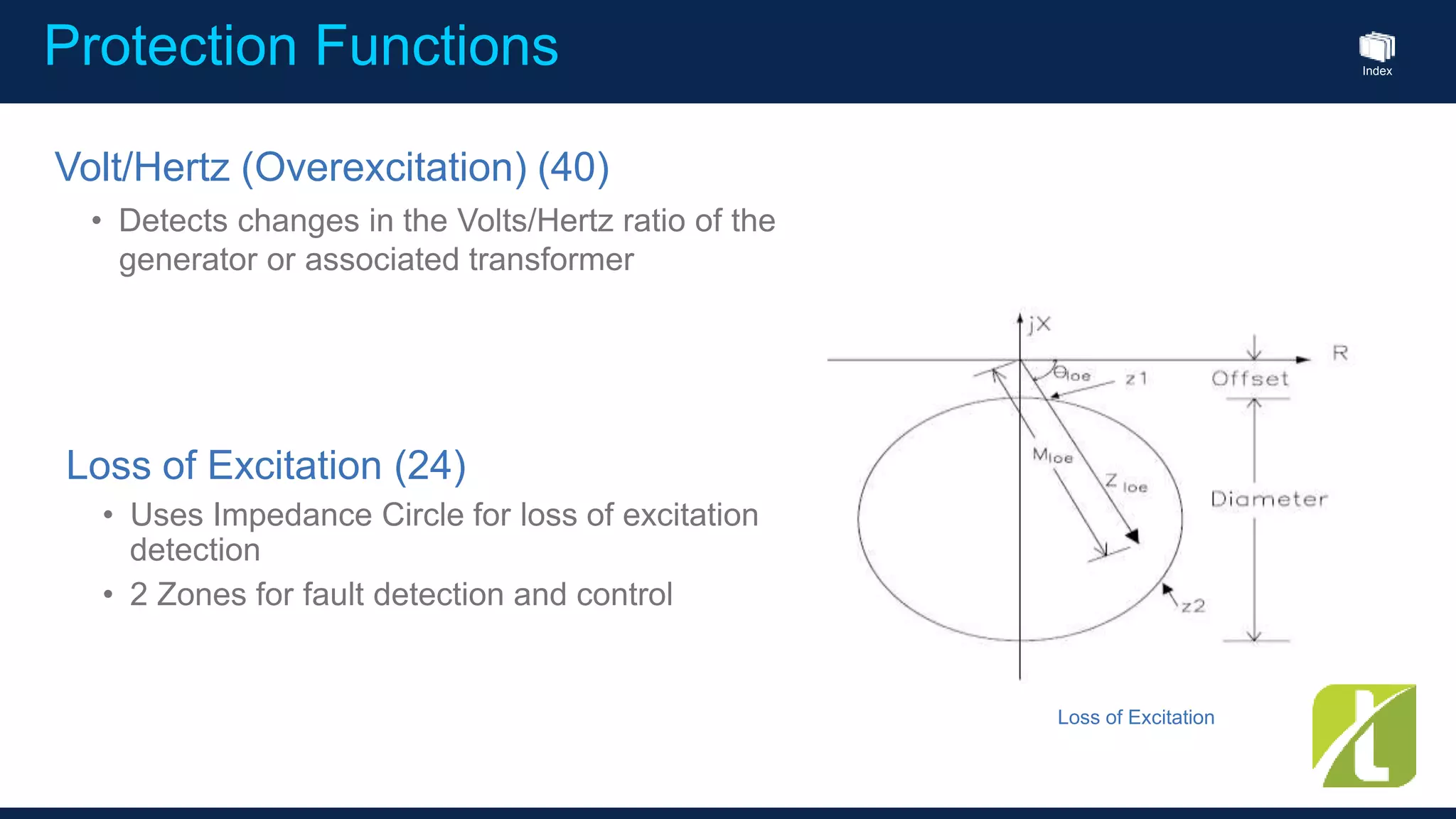
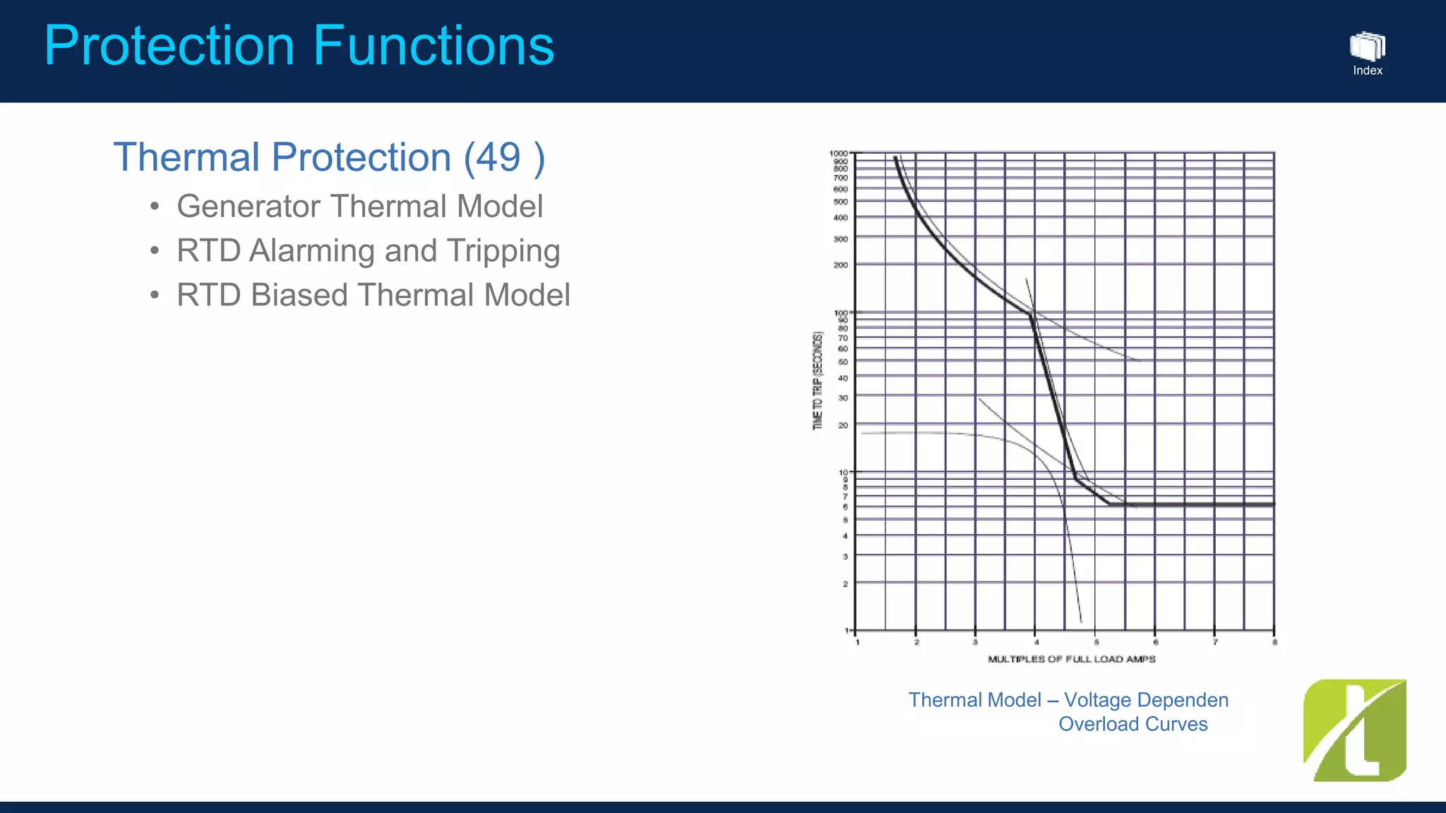
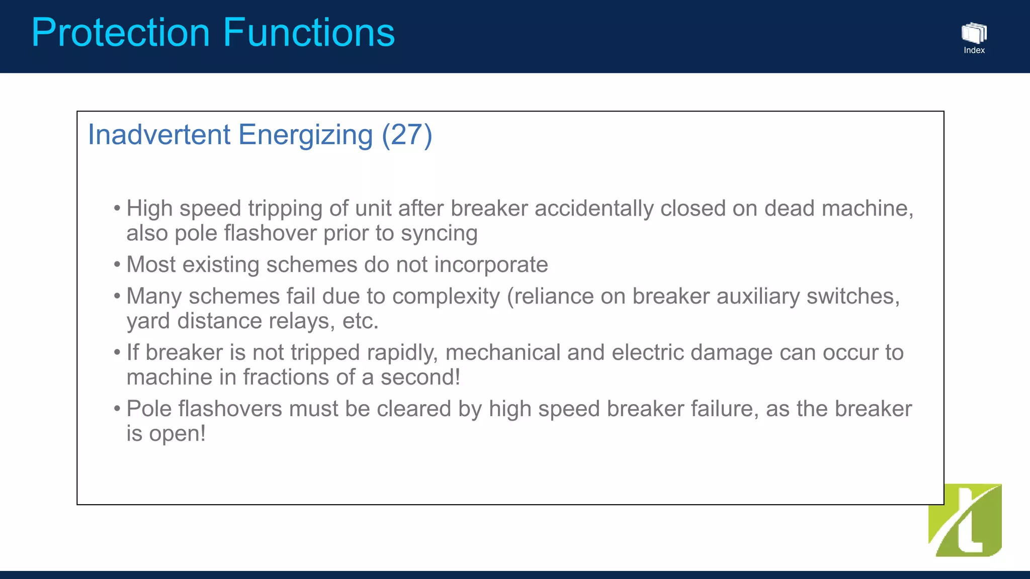
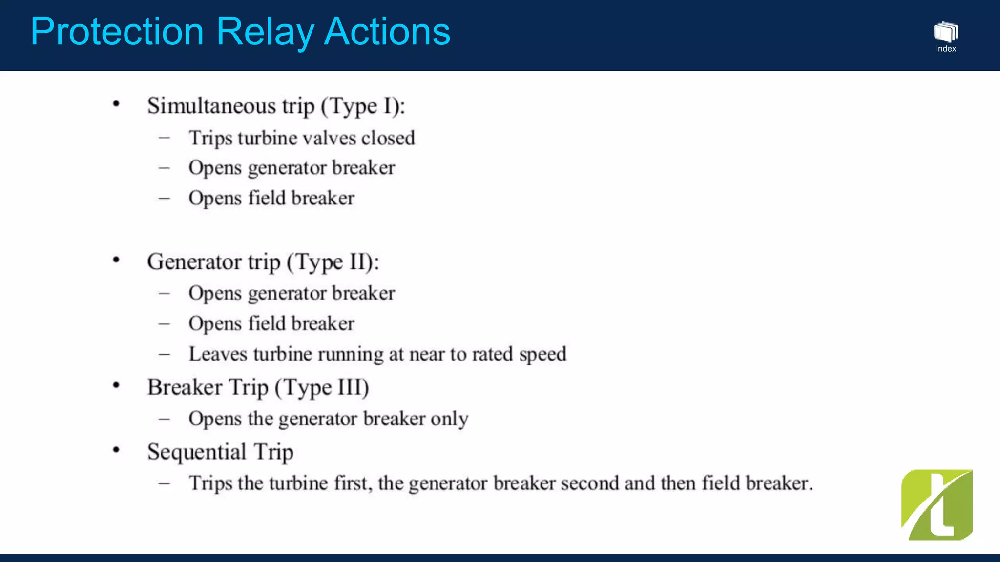
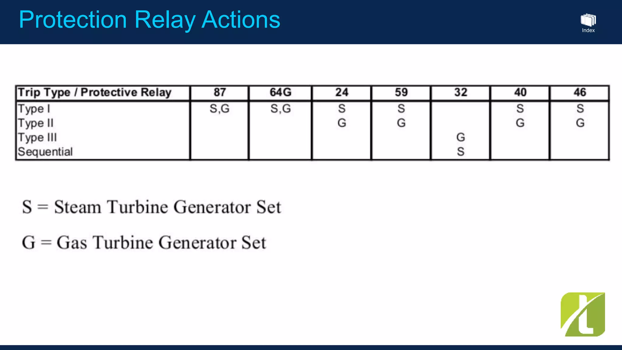
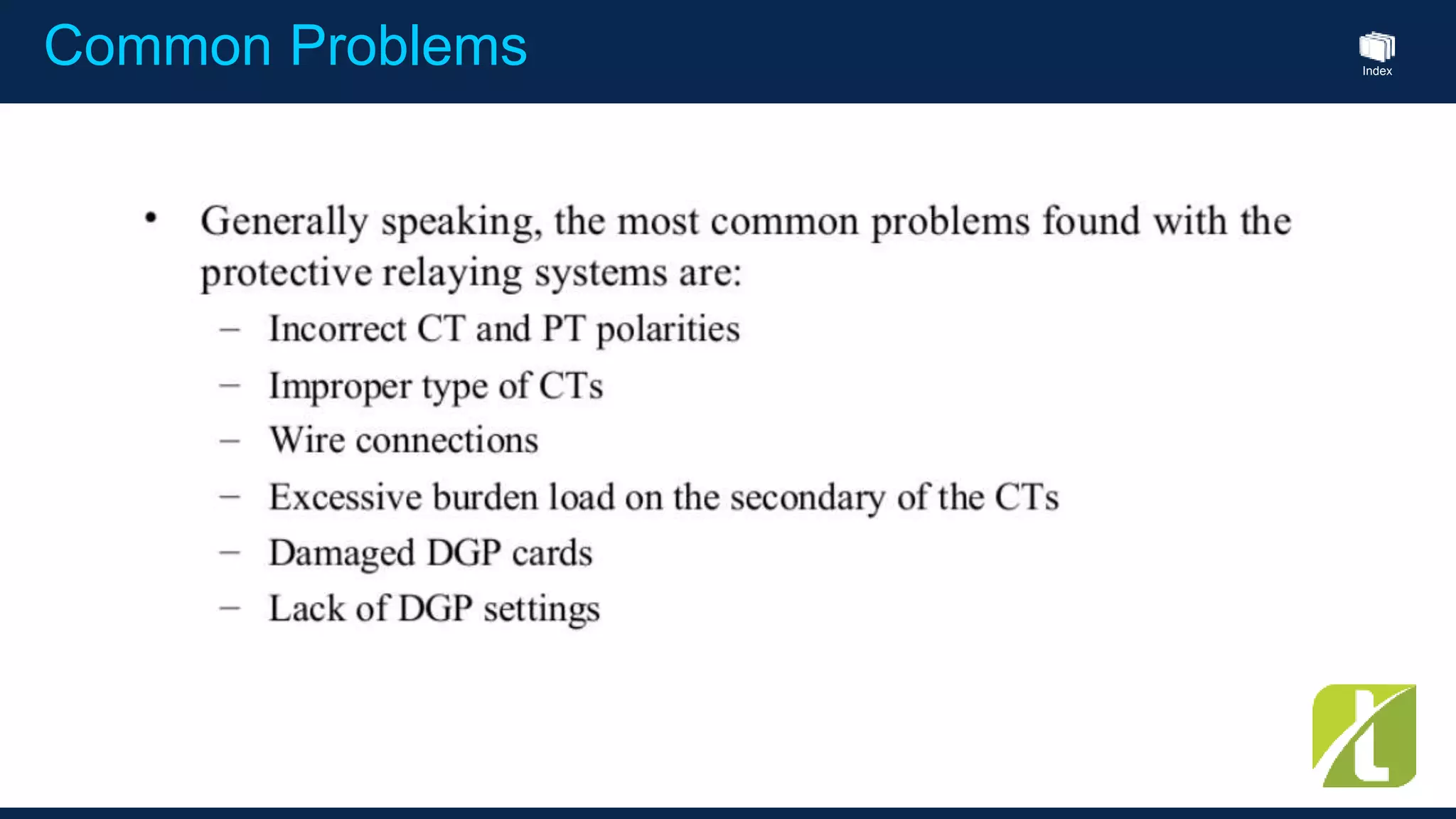
Index
This Seminar is Proudly Sponsored by :
TRUST SYNERGY INTERNATIONAL
by Nicholas Naing
GENERATOR PROTECTION SYSTEM
Index
1.00 p.m : Welcome Speech by YTU Electrical Power Department Head
1.10 p.m : Introduction to the Speaker
1.15 p.m : Generator Protection Systems
1.50 p.m : Tea Break
2.00 p.m : Protection Functions Detail
2.40 p.m : Question and Answer Section
3.00 p.m : End of Presentation
Agenta : 13th JAN 2016 , 1 p.m ~ 3 p.m , YTU
IndexOverview
Generator
Abnormal Operating Conditions
Loss of Synchronism
Abnormal Frequency
Over excitation
Field Loss
Inadvertent Energizing
Breaker Failure
Loss of Prime Mover Power
Blown VT Fuses
Open Circuits
Index
The
"Wild"
Power
System
G
Exciter
Loss of Field
Loss of Field
Overexcitation
Overexcitation
Overexcitation
Open
Circuits
Loss of
Synchronism
Inadvertent
Energizing,
Pole Flashover
Abnormal
Frequency
Abnormal
Frequency
Breaker
Failure
Reverse
Power
Over
Power
What Really happened ?
IndexWhat Really happened ?
The
"Wild"
Power
System
G
Exciter
Stator
Ground
Stator
Phase
System
Ground
System
Phase
Index
Protection Functions
• Generator Stator Differential
• Backup Distance Protection
• 100% Stator Ground
• Generator Unbalance
• Loss of Excitation
• Accidental Energization
• Breaker Fail
• Phase Overcurrent – Voltage Restraint
• Neutral Inst. / Timed Overcurrent
• Neg. Sequence Overcurrent
• Under / Over Voltage
• Under / Over Frequency
• Generator Thermal Model
• RTD Temperature
• Overexcitation – Volts/Hertz
Index
Small Generator Protection (IEEE)
32 Reverse Power
40 Loss of Excitation
51V voltage restraint
51G Ground overcurrent
87 Differential
Small Size – up to 1 MW
Index
Medium Generator Protection (IEEE)
Medium Size – up to 12.5 MW
32 Reverse Power
40 Loss of Excitation
46 Negative Sequence
51V voltage restraint
51G Ground overcurrent
87 Differential
Index
Large Generator Protection (IEEE)
Large Size – Up to 50 MW
32 Reverse Power
40 Loss of Excitation
46 Negative Sequence
49 Thermal Overload
51V voltage restraint
51G Ground overcurrent
64 Ground Relay
87 Differential
Index
Large Generator Protection (IEEE)
Large Size – above 50 MW
32 Reverse Power
40 Loss of Excitation
46 Negative Sequence
49 Thermal Overload
51V voltage restraint
51G Ground overcurrent
64 Ground Relay
87 Differential
Index
Sample Generator Protection Relay Wiring
Index
Sample Generator Protection Relay Wiring
Index
Sample Generator Protection Relay Wiring
Index
Sample Generator Protection Relay Wiring
Index
binary w. cable supervision inputs
Three-phase V AC
(110-690V AC)
Three-phase I AC
MPU pickup/
Dig. running/
Ana. running
Crank
Start prepare
Run/stop coil
Three multi inputs: PT 100/1000, (0)4..20mA, VDO, 0..40V
Emergency stop
Start enable
Sample Generator Protection with Relay
Index
16 diesel generators15 diesel generators & 1 emergency generator8 bustie breakers2 shaft generators2 shore connectionsWrapped busbar possibillity
Sample Generators Parallel Setup
Index
Break
Index
Desirable Attributes of Generator
Protection ANSI number Levels Standard
Phase sequence voltage 47 1 ×
Generator reverse power (2×) 32 2 ×
Generator overcurrent (4×) 50 4 ×
Voltage-dependent overcurrent 51V 1 ×
Fast overcurrent (2×) 51 2 ×
Generator overvoltage (2×) 59 2 ×
Generator undervoltage (3×) 27 3 ×
Generator overfrequency (3×) 81 3 ×
Generator underfrequency (3×) 81 3 ×
Busbar overvoltage (3×) 59B 3 ×
Busbar undervoltage (4×) 27B 4 ×
Busbar overfrequency (3×) 81B 3 ×
Busbar underfrequency (4×) 81B 4 ×
Generator overload (5×) 32 5 ×
Current/voltage unbalance 60 1 ×
Over excitation 24 1 ×
Loss of excitation 40 1 ×
Alarm relay 74 1 ×
Trip of non-essential load 3 3 groups
Index
Generator Management Relay Sample
Index
Protection Functions
Generator Stator Differential (87)
• Stator Phase Differential
• Dual Slope Percent Restraint Operating
Characteristic
• Directional Supervision under saturation
conditions
Distance Protection (21/21N)
• set based in percentages of the line
impedances
• zone 1 is 80% of the impedance of the line in
order to not reach the remote end, the
• zone 2 can be set at 120% of the impedance of
the line in order to dependably overreach the
line,
• zone 3 sometimes are disabled or set to cover
an adjacent line.
Index
Protection Functions
Over Excitation ( 24 )
Index
Protection Functions
Voltage Protection (59)
• Phase Overvoltage
• Phase Undervoltage
• Neutral Overvoltage (fundamental)
• Neutral Undervoltage (3rd Harmonic)
• Voltage Phase Reversal
Voltage Restraint Overcurrent
Undervoltage Trip Curves
Index
Protection Functions
Current Protection (50)
• Phase, Ground and Negative Sequence
Overcurrent Tripping
• IEC, ANSI , IAC and Customizable
Overcurrent Curves
• Voltage Restraint increasing sensitivity under
low voltage conditions
Index
Protection Functions
Frequency Protection (81)
• Overfrequency (81O)
• Underfrequency (81U)
100% Stator Ground Protection (59N/59D)
Protects all of the stator winding
Existing schemes typically only see 90%
Stop low level fault near neutral from
degrading into a high level fault and causing
large amounts of damage
Index
Protection Functions
Reverse Power (32)
Should be sensitive to 0.05 pu to properly detect motoring in large steam turbines
Existing E/M and Static relays not sensitive enough
May cause shutdown difficulties
Negative Sequence (46)
Should be sensitive to low values to detect open poles/conductors on system after
GSU
Existing E/M and Static relays not sensitive enough
Long time low level events may cause excessive rotor heating, thermal tripping and
damage rotor
Index
Protection Functions
Volt/Hertz (Overexcitation) (40)
• Detects changes in the Volts/Hertz ratio of the
generator or associated transformer
Loss of Excitation
Loss of Excitation (24)
• Uses Impedance Circle for loss of excitation
detection
• 2 Zones for fault detection and control
Index
Protection Functions
Thermal Protection (49 )
• Generator Thermal Model
• RTD Alarming and Tripping
• RTD Biased Thermal Model
Thermal Model – Voltage Dependen
Overload Curves
Index
Protection Functions
Inadvertent Energizing (27)
• High speed tripping of unit after breaker accidentally closed on dead machine,
also pole flashover prior to syncing
• Most existing schemes do not incorporate
• Many schemes fail due to complexity (reliance on breaker auxiliary switches,
yard distance relays, etc.
• If breaker is not tripped rapidly, mechanical and electric damage can occur to
machine in fractions of a second!
• Pole flashovers must be cleared by high speed breaker failure, as the breaker
is open!
Index
Protection Relay Actions
Index
Protection Relay Actions
Index
Common Problems
Index
Contact Detail :
Nicholas Naing
naingwhbiz@gmail.com
#KoNaingYIT
Electrical Notes by Ko Naing YIT
Index
Index
THANK
YOU

Generator protection system by nicholas naing

  • 1.
    Index This Seminar isProudly Sponsored by : TRUST SYNERGY INTERNATIONAL
  • 2.
    by Nicholas Naing GENERATORPROTECTION SYSTEM
  • 3.
    Index 1.00 p.m :Welcome Speech by YTU Electrical Power Department Head 1.10 p.m : Introduction to the Speaker 1.15 p.m : Generator Protection Systems 1.50 p.m : Tea Break 2.00 p.m : Protection Functions Detail 2.40 p.m : Question and Answer Section 3.00 p.m : End of Presentation Agenta : 13th JAN 2016 , 1 p.m ~ 3 p.m , YTU
  • 4.
    IndexOverview Generator Abnormal Operating Conditions Lossof Synchronism Abnormal Frequency Over excitation Field Loss Inadvertent Energizing Breaker Failure Loss of Prime Mover Power Blown VT Fuses Open Circuits
  • 5.
    Index The "Wild" Power System G Exciter Loss of Field Lossof Field Overexcitation Overexcitation Overexcitation Open Circuits Loss of Synchronism Inadvertent Energizing, Pole Flashover Abnormal Frequency Abnormal Frequency Breaker Failure Reverse Power Over Power What Really happened ?
  • 6.
    IndexWhat Really happened? The "Wild" Power System G Exciter Stator Ground Stator Phase System Ground System Phase
  • 7.
    Index Protection Functions • GeneratorStator Differential • Backup Distance Protection • 100% Stator Ground • Generator Unbalance • Loss of Excitation • Accidental Energization • Breaker Fail • Phase Overcurrent – Voltage Restraint • Neutral Inst. / Timed Overcurrent • Neg. Sequence Overcurrent • Under / Over Voltage • Under / Over Frequency • Generator Thermal Model • RTD Temperature • Overexcitation – Volts/Hertz
  • 8.
    Index Small Generator Protection(IEEE) 32 Reverse Power 40 Loss of Excitation 51V voltage restraint 51G Ground overcurrent 87 Differential Small Size – up to 1 MW
  • 9.
    Index Medium Generator Protection(IEEE) Medium Size – up to 12.5 MW 32 Reverse Power 40 Loss of Excitation 46 Negative Sequence 51V voltage restraint 51G Ground overcurrent 87 Differential
  • 10.
    Index Large Generator Protection(IEEE) Large Size – Up to 50 MW 32 Reverse Power 40 Loss of Excitation 46 Negative Sequence 49 Thermal Overload 51V voltage restraint 51G Ground overcurrent 64 Ground Relay 87 Differential
  • 11.
    Index Large Generator Protection(IEEE) Large Size – above 50 MW 32 Reverse Power 40 Loss of Excitation 46 Negative Sequence 49 Thermal Overload 51V voltage restraint 51G Ground overcurrent 64 Ground Relay 87 Differential
  • 12.
  • 13.
  • 14.
  • 15.
  • 16.
    Index binary w. cablesupervision inputs Three-phase V AC (110-690V AC) Three-phase I AC MPU pickup/ Dig. running/ Ana. running Crank Start prepare Run/stop coil Three multi inputs: PT 100/1000, (0)4..20mA, VDO, 0..40V Emergency stop Start enable Sample Generator Protection with Relay
  • 17.
    Index 16 diesel generators15diesel generators & 1 emergency generator8 bustie breakers2 shaft generators2 shore connectionsWrapped busbar possibillity Sample Generators Parallel Setup
  • 18.
  • 19.
    Index Desirable Attributes ofGenerator Protection ANSI number Levels Standard Phase sequence voltage 47 1 × Generator reverse power (2×) 32 2 × Generator overcurrent (4×) 50 4 × Voltage-dependent overcurrent 51V 1 × Fast overcurrent (2×) 51 2 × Generator overvoltage (2×) 59 2 × Generator undervoltage (3×) 27 3 × Generator overfrequency (3×) 81 3 × Generator underfrequency (3×) 81 3 × Busbar overvoltage (3×) 59B 3 × Busbar undervoltage (4×) 27B 4 × Busbar overfrequency (3×) 81B 3 × Busbar underfrequency (4×) 81B 4 × Generator overload (5×) 32 5 × Current/voltage unbalance 60 1 × Over excitation 24 1 × Loss of excitation 40 1 × Alarm relay 74 1 × Trip of non-essential load 3 3 groups
  • 20.
  • 21.
    Index Protection Functions Generator StatorDifferential (87) • Stator Phase Differential • Dual Slope Percent Restraint Operating Characteristic • Directional Supervision under saturation conditions Distance Protection (21/21N) • set based in percentages of the line impedances • zone 1 is 80% of the impedance of the line in order to not reach the remote end, the • zone 2 can be set at 120% of the impedance of the line in order to dependably overreach the line, • zone 3 sometimes are disabled or set to cover an adjacent line.
  • 22.
  • 23.
    Index Protection Functions Voltage Protection(59) • Phase Overvoltage • Phase Undervoltage • Neutral Overvoltage (fundamental) • Neutral Undervoltage (3rd Harmonic) • Voltage Phase Reversal Voltage Restraint Overcurrent Undervoltage Trip Curves
  • 24.
    Index Protection Functions Current Protection(50) • Phase, Ground and Negative Sequence Overcurrent Tripping • IEC, ANSI , IAC and Customizable Overcurrent Curves • Voltage Restraint increasing sensitivity under low voltage conditions
  • 25.
    Index Protection Functions Frequency Protection(81) • Overfrequency (81O) • Underfrequency (81U) 100% Stator Ground Protection (59N/59D) Protects all of the stator winding Existing schemes typically only see 90% Stop low level fault near neutral from degrading into a high level fault and causing large amounts of damage
  • 26.
    Index Protection Functions Reverse Power(32) Should be sensitive to 0.05 pu to properly detect motoring in large steam turbines Existing E/M and Static relays not sensitive enough May cause shutdown difficulties Negative Sequence (46) Should be sensitive to low values to detect open poles/conductors on system after GSU Existing E/M and Static relays not sensitive enough Long time low level events may cause excessive rotor heating, thermal tripping and damage rotor
  • 27.
    Index Protection Functions Volt/Hertz (Overexcitation)(40) • Detects changes in the Volts/Hertz ratio of the generator or associated transformer Loss of Excitation Loss of Excitation (24) • Uses Impedance Circle for loss of excitation detection • 2 Zones for fault detection and control
  • 28.
    Index Protection Functions Thermal Protection(49 ) • Generator Thermal Model • RTD Alarming and Tripping • RTD Biased Thermal Model Thermal Model – Voltage Dependen Overload Curves
  • 29.
    Index Protection Functions Inadvertent Energizing(27) • High speed tripping of unit after breaker accidentally closed on dead machine, also pole flashover prior to syncing • Most existing schemes do not incorporate • Many schemes fail due to complexity (reliance on breaker auxiliary switches, yard distance relays, etc. • If breaker is not tripped rapidly, mechanical and electric damage can occur to machine in fractions of a second! • Pole flashovers must be cleared by high speed breaker failure, as the breaker is open!
  • 30.
  • 31.
  • 32.
  • 33.
    Index Contact Detail : NicholasNaing naingwhbiz@gmail.com #KoNaingYIT Electrical Notes by Ko Naing YIT
  • 34.
  • 35.