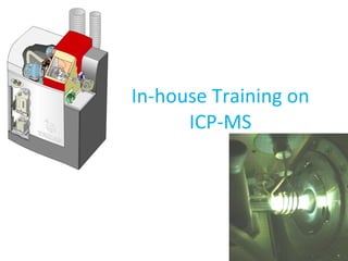
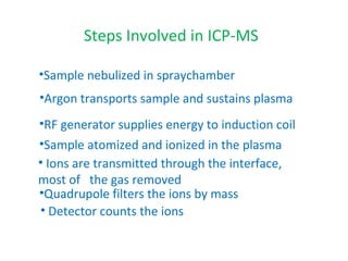
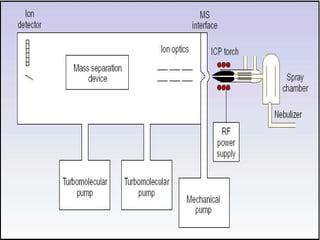
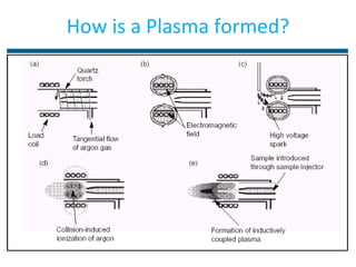
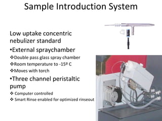
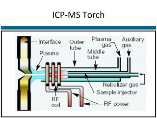
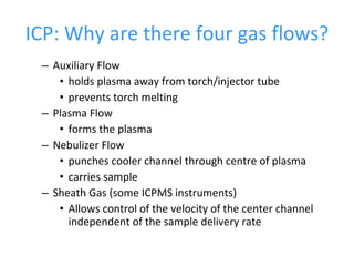
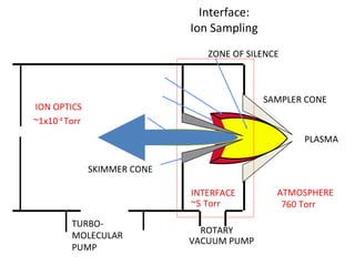
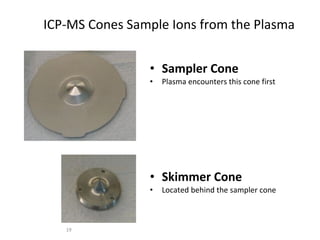
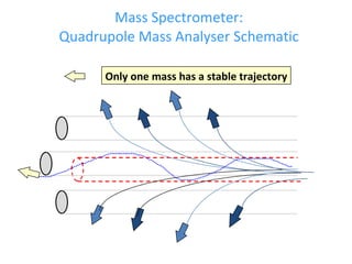
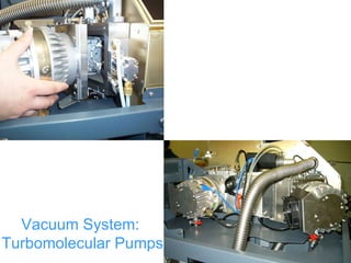
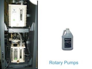
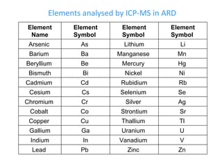
In-house Training on ICP-MS
ICP-MS??? Inductively Coupled Plasma Mass Spectrometry or ICP-MS is an analytical technique used for elemental determinations.  An ICP-MS combines a high-temperature ICP (Inductively Coupled Plasma) source with a mass spectrometer.  The ICP source converts the atoms of the elements in the sample to ions.  These ions are then separated and detected by the mass spectrometer.
Atomic Spectroscopy Techniques Three techniques share the same basic components Atomic Absorption (Flame and Furnace) ICP-AES ICP-MS All three are used for the analysis of metals
Comparison of Techniques ICP-MS ICP-AES GFAAS FAAS Detection Limits Excellent Good Excellent Good Productivity Excellent Excellent Low Good Precision 1-3% 0.3 – 2 % 1 – 5 % 0.1 – 1 % Chemical Interferences Moderate Few Many Many Ionization Minimal Minimal Minimal Some Mass Effects High on low mass None None None Dissolved solids 0.1 – 0.4 % 2 – 25 % Up to 20 % 0.5 – 3 % # Elements 75 73 50 68 Sample Usage Low Medium Very Low High Isotope Analysis Yes No No No Method Development Skill required Skill required Skill required Easy Running Costs High High Medium Low Capital Costs Very high High Medium Low
ICP-MS Components • Sample Introduction • Plasma Generation • Interface • Ion Optics • Mass Analyzer • Vacuum System
• Sample Introduction Delivers finely divided sample (usually aerosol) to plasma • Plasma Source Ion Source Ar plasma 10 000K • Interface Allows transfer of atmospheric pressure ion source to high-vacuum mass analyser
Ion Optics Focuses ion beam and helps eliminate neutral species and photons • Mass Analyzer Separates and measures individual ions by mass • Vacuum System Provides low pressure environment for mass spectrometer to operate effectively (no collisional losses) Enables transition from plasma to high-vacuum via interface region
The Detector Converts ions into electrical pulses Magnitude of the electrical pulse is proportional to the number of ions in sample
Sample nebulized in spraychamber Argon transports sample and sustains plasma RF generator supplies energy to induction coil Sample atomized and ionized in the plasma Ions are transmitted through the interface, most of  the gas removed Quadrupole filters the ions by mass Detector counts the ions Steps Involved in ICP-MS
 
How is a Plasma formed?
Sample Introduction System Low uptake concentric nebulizer standard External spraychamber Double pass glass spray chamber Room temperature to -15º C Moves with torch Three channel peristaltic pump Computer controlled Smart Rinse enabled for optimized rinseout
The Plasma •  A plasma is a cloud of ionized gas •  Plasma temperature 6000 - 7000 K •  Most elements >90% ionized •  Singly charged positive ions predominate •  Small molecular and doubly charged ion population •  Complete elemental analysis in a single determination
ICP-MS Torch
Process to form Plasma • A flow of argon gas is passed between outer and middle tube of torch •  RF power is applied to load coil producing intense electromagnetic field •  A high-voltage spark produces free electrons •  Free electrons are accelerated by electric field •  Accelerated free electrons produce high energy collision and ionization of Argon gas •  Self-sustaining plasma is formed at open end of quartz torch
Processes in the Plasma Recombination  ←  Ionisation  ←  Atomisation   ←   Vaporisation Oxides   ←  Ions  ←  Atoms  ←  Gas  ←  Solid ←  Liquid Sample aerosol M(H 2 0) +  X- MXn MX MX M+ MO+
ICP: Why are there four gas flows? Auxiliary Flow holds plasma away from torch/injector tube prevents torch melting Plasma Flow forms the plasma Nebulizer Flow punches cooler channel through centre of plasma carries sample Sheath Gas (some ICPMS instruments) Allows control of the velocity of the center channel independent of the sample delivery rate
Interface: Ion Sampling TURBO-MOLECULAR PUMP VACUUM PUMP SAMPLER CONE SKIMMER CONE PLASMA ZONE OF SILENCE INTERFACE ~5 Torr ATMOSPHERE   760 Torr ROTARY  ION OPTICS   ~1x10 -4  Torr
ICP-MS Cones Sample Ions from the Plasma Sampler Cone Plasma encounters this cone first Skimmer Cone Located behind the sampler cone
The Mass Spectrometer Responsible for the high sensitivity of ICPMS instruments. Separates ionized species on the basis of their mass to charge ratio. Requires high vacuum (~ 10 -6  Torr) to operate Resolution must allow detection of low concentration elements in presence of adjacent high concentration elements. Scanning speed must be fast enough to cope with transient signals from various sample introduction systems Must accept a wide distribution of ion energies
Mass Spectrometer: Common Mass Analyzers Quadrupole Ion Trap Time of Flight Double-Focusing Magnetic Sector
Mass Spectrometer: Quadrupole Mass Analyser Schematic Only one mass has a stable trajectory
Vacuum System: Turbomolecular Pumps
Rotary Pumps
Elements analysed by ICP-MS in ARD Element Name Element Symbol  Element Symbol  Element Symbol  Arsenic  As  Lithium Li Barium  Ba  Manganese  Mn  Beryllium  Be  Mercury  Hg  Bismuth Bi Nickel  Ni  Cadmium  Cd  Rubidium Rb Cesium Cs Selenium  Se  Chromium  Cr  Silver  Ag  Cobalt  Co  Strontium Sr Copper  Cu  Thallium  Tl  Gallium Ga Uranium  U  Indium In Vanadium  V  Lead  Pb  Zinc  Zn
Analysis of Samples by ICP-MS Follow BCSIR SOP – 22  Prepare tuning solution Prepare standard solution of metals of different concentrations Always use de-ionized water having a resistivity  of 17.5–18.5 MΩ/cm  Use suprapure ICP-MS grade acids
Seven Elements of Quality Control during sample analysis by ICP-MS   Certification of operator competence Calibration Analysis of externally supplied standards Analysis of blanks Analysis of duplicates  Recovery of known additions Control charts
The End

Icp ms

  • 1.
  • 2.
    ICP-MS??? Inductively CoupledPlasma Mass Spectrometry or ICP-MS is an analytical technique used for elemental determinations. An ICP-MS combines a high-temperature ICP (Inductively Coupled Plasma) source with a mass spectrometer. The ICP source converts the atoms of the elements in the sample to ions. These ions are then separated and detected by the mass spectrometer.
  • 3.
    Atomic Spectroscopy TechniquesThree techniques share the same basic components Atomic Absorption (Flame and Furnace) ICP-AES ICP-MS All three are used for the analysis of metals
  • 4.
    Comparison of TechniquesICP-MS ICP-AES GFAAS FAAS Detection Limits Excellent Good Excellent Good Productivity Excellent Excellent Low Good Precision 1-3% 0.3 – 2 % 1 – 5 % 0.1 – 1 % Chemical Interferences Moderate Few Many Many Ionization Minimal Minimal Minimal Some Mass Effects High on low mass None None None Dissolved solids 0.1 – 0.4 % 2 – 25 % Up to 20 % 0.5 – 3 % # Elements 75 73 50 68 Sample Usage Low Medium Very Low High Isotope Analysis Yes No No No Method Development Skill required Skill required Skill required Easy Running Costs High High Medium Low Capital Costs Very high High Medium Low
  • 5.
    ICP-MS Components •Sample Introduction • Plasma Generation • Interface • Ion Optics • Mass Analyzer • Vacuum System
  • 6.
    • Sample IntroductionDelivers finely divided sample (usually aerosol) to plasma • Plasma Source Ion Source Ar plasma 10 000K • Interface Allows transfer of atmospheric pressure ion source to high-vacuum mass analyser
  • 7.
    Ion Optics Focusesion beam and helps eliminate neutral species and photons • Mass Analyzer Separates and measures individual ions by mass • Vacuum System Provides low pressure environment for mass spectrometer to operate effectively (no collisional losses) Enables transition from plasma to high-vacuum via interface region
  • 8.
    The Detector Convertsions into electrical pulses Magnitude of the electrical pulse is proportional to the number of ions in sample
  • 9.
    Sample nebulized inspraychamber Argon transports sample and sustains plasma RF generator supplies energy to induction coil Sample atomized and ionized in the plasma Ions are transmitted through the interface, most of the gas removed Quadrupole filters the ions by mass Detector counts the ions Steps Involved in ICP-MS
  • 10.
  • 11.
    How is aPlasma formed?
  • 12.
    Sample Introduction SystemLow uptake concentric nebulizer standard External spraychamber Double pass glass spray chamber Room temperature to -15º C Moves with torch Three channel peristaltic pump Computer controlled Smart Rinse enabled for optimized rinseout
  • 13.
    The Plasma • A plasma is a cloud of ionized gas • Plasma temperature 6000 - 7000 K • Most elements >90% ionized • Singly charged positive ions predominate • Small molecular and doubly charged ion population • Complete elemental analysis in a single determination
  • 14.
  • 15.
    Process to formPlasma • A flow of argon gas is passed between outer and middle tube of torch • RF power is applied to load coil producing intense electromagnetic field • A high-voltage spark produces free electrons • Free electrons are accelerated by electric field • Accelerated free electrons produce high energy collision and ionization of Argon gas • Self-sustaining plasma is formed at open end of quartz torch
  • 16.
    Processes in thePlasma Recombination ← Ionisation ← Atomisation ← Vaporisation Oxides ← Ions ← Atoms ← Gas ← Solid ← Liquid Sample aerosol M(H 2 0) + X- MXn MX MX M+ MO+
  • 17.
    ICP: Why arethere four gas flows? Auxiliary Flow holds plasma away from torch/injector tube prevents torch melting Plasma Flow forms the plasma Nebulizer Flow punches cooler channel through centre of plasma carries sample Sheath Gas (some ICPMS instruments) Allows control of the velocity of the center channel independent of the sample delivery rate
  • 18.
    Interface: Ion SamplingTURBO-MOLECULAR PUMP VACUUM PUMP SAMPLER CONE SKIMMER CONE PLASMA ZONE OF SILENCE INTERFACE ~5 Torr ATMOSPHERE 760 Torr ROTARY ION OPTICS ~1x10 -4 Torr
  • 19.
    ICP-MS Cones SampleIons from the Plasma Sampler Cone Plasma encounters this cone first Skimmer Cone Located behind the sampler cone
  • 20.
    The Mass SpectrometerResponsible for the high sensitivity of ICPMS instruments. Separates ionized species on the basis of their mass to charge ratio. Requires high vacuum (~ 10 -6 Torr) to operate Resolution must allow detection of low concentration elements in presence of adjacent high concentration elements. Scanning speed must be fast enough to cope with transient signals from various sample introduction systems Must accept a wide distribution of ion energies
  • 21.
    Mass Spectrometer: CommonMass Analyzers Quadrupole Ion Trap Time of Flight Double-Focusing Magnetic Sector
  • 22.
    Mass Spectrometer: QuadrupoleMass Analyser Schematic Only one mass has a stable trajectory
  • 23.
  • 24.
  • 25.
    Elements analysed byICP-MS in ARD Element Name Element Symbol Element Symbol Element Symbol Arsenic As Lithium Li Barium Ba Manganese Mn Beryllium Be Mercury Hg Bismuth Bi Nickel Ni Cadmium Cd Rubidium Rb Cesium Cs Selenium Se Chromium Cr Silver Ag Cobalt Co Strontium Sr Copper Cu Thallium Tl Gallium Ga Uranium U Indium In Vanadium V Lead Pb Zinc Zn
  • 26.
    Analysis of Samplesby ICP-MS Follow BCSIR SOP – 22 Prepare tuning solution Prepare standard solution of metals of different concentrations Always use de-ionized water having a resistivity of 17.5–18.5 MΩ/cm Use suprapure ICP-MS grade acids
  • 27.
    Seven Elements ofQuality Control during sample analysis by ICP-MS Certification of operator competence Calibration Analysis of externally supplied standards Analysis of blanks Analysis of duplicates Recovery of known additions Control charts
  • 28.

Editor's Notes

  • #4 11/21/11
  • #5 11/21/11
  • #17 11/21/11 This is a overview of the processes that take place for a metal ion (M) as it enters the torch and passes through the plasma.
  • #18 11/21/11
  • #19 11/21/11 The interface assembly provides a means of sampling the atmospheric pressure gases created in the plasma into a vacuum chamber and separates most of the unwanted gas stream from the ion beam. All ICP-MS instruments have one. Assembly always consists of two metal cones with small orifices at their tips mounted one behind the other, usually known as the “sampler” and “skimmer” cones, respectively. These are mounted in a large metal block that is water-cooled to dissipate the heat absorbed from the plasma. The region between the cones is kept at 1- 5 torr using a mechanical rotary vacuum pump. Ion extraction is performed with very little opportunity for gas-phase reactions –the gas forms a supersonic jet as it accelerates into the vacuum and cools so quickly that there is very little chance for secondary reactions to occur. The skimmer cone is placed inside the supersonic jet; ions are extracted into the mass spectrometer, most of the gases are lost as they are deflected around the tip of the cone. This results in a collimated ion beam which then passes through the ion optics for further focusing and elimination of neutral species.
  • #20 Plasma interface consists of two cones: a sampler cone and a skimmer cone. The skimmer cone is located downstream of the sampler cone in the instrument. The function of the cones is to enable sampling of ions from the plasma.
  • #21 11/21/11
  • #22 11/21/11 There are many different types of mass spectrometers (used in many other instruments besides ICPMS). All of the types of mass spectrometers listed above have been used for ICPMS, but we will focus in this presentation on the quadrupole mass spectrometer, as this configuration is used in the vast majority of all ICPMS instruments.
  • #23 11/21/11 For a given set of RF/DC conditions in the quadrupole, only one mass will have a stable trajectory through the mass analyzer, all other ions will be lost. The RF/DC settings can be altered very quickly (<1ms) and this is how the mass spectrometer scans across the entire mass range. Precision assembly of 4 electrically conducting rods to which RF and DC voltages are applied opposing rod pairs, opposite polarity resulting electric fields in the center of the assembly filters the ions by mass only one mass/charge ratio has stable trajectory, others are excluded RF/DC ratio determines resolution Rigid, stable geometry, no moving parts Compact size Accepts ions of a wide energy range Good resolution/mass range capabilities for atomic spectroscopy