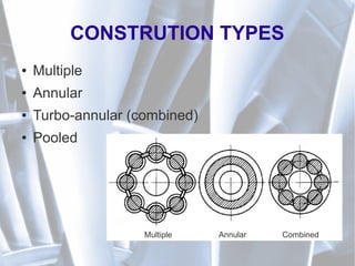
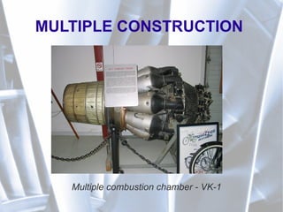
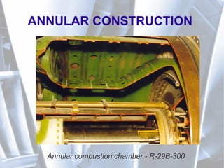
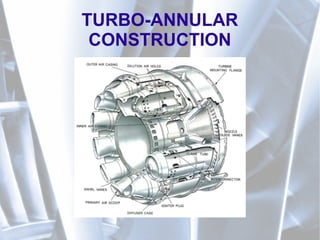
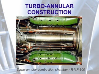
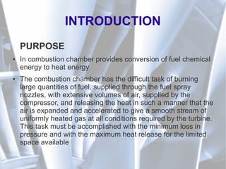
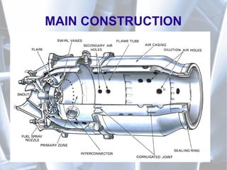
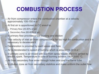
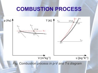
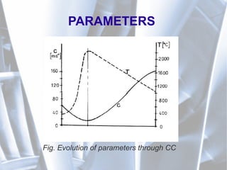
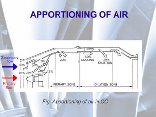
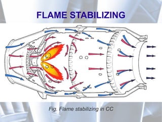
This document discusses jet engine combustion chambers. It describes the purpose of combustion chambers as converting fuel chemical energy to heat energy. Some key requirements are easy and safe ignition, stable burning, and uniform pressure and velocity fields. Main challenges include high heat loads, temperatures over 2000K, and ensuring stable ignition and burning. The combustion process involves air entering and being apportioned between primary and secondary flows before mixing with fuel and igniting. Parameters like pressure, temperature and flows are discussed along with combustion chamber construction types such as multiple, annular and turbo-annular designs.


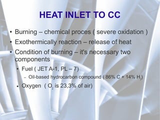
![HEAT INLET TO CC
● Qualitatively ( from molecular weight):
12kg C + 32kg.O2
→44kg.O2
+ heat
1kg C + 8/3kg.O2
→11/3kg.CO2
+ 33.106
[J]
2kg H2
+16kg.O2
→ 18kg.H2
O + heat
1kg.H2
+8kg.O2
→ 9kg.H2
O + 121.106
[J]](https://image.slidesharecdn.com/209368303-gas-turbine-combustion-chambers-150619140738-lva1-app6892/85/209368303-gas-turbine-combustion-chambers-14-320.jpg)
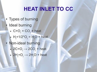
![NECESSARY OXYGEN/AIR
● Of course l0
is not enough, because temperature of gases is too high and its
necessary to mix with cooler air. Its mean that is necessary provide α*l0
air
for burning of 1kg of fuel
Qv
– air flow through CC [kg.s-1]
Qf
– fuel flow through CC [kg.s-1]
α – coefficient of air overflow [1] (3,5 – 4,5)
l0
– theoretical quantity of air for burning of 1kg hydrocarbon fuel
Qv=Q f l0](https://image.slidesharecdn.com/209368303-gas-turbine-combustion-chambers-150619140738-lva1-app6892/85/209368303-gas-turbine-combustion-chambers-16-320.jpg)
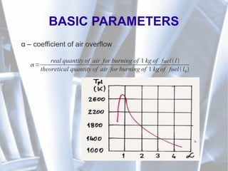
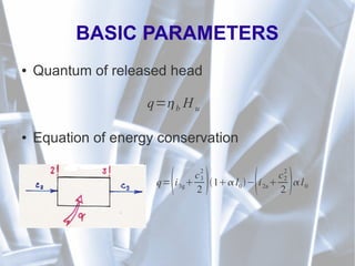
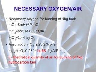
![BASIC PARAMETERS
● Heat (calorific) value of fuel Hu
● Define heat properties of fuel
● Define a quantity of heat at ideal fuel burn
● For PL-6 – 43123 [kJ.kg-1
]
● Heat (calorific) value of mixture Hum
H um=
H u
1 l0](https://image.slidesharecdn.com/209368303-gas-turbine-combustion-chambers-150619140738-lva1-app6892/85/209368303-gas-turbine-combustion-chambers-18-320.jpg)
![BASIC PARAMETERS
● Absolute pressure losses
● Burning efficiency
CC=
p3T
p2T
[1]
b=
real heat release during burning
theoretical heat release during burning](https://image.slidesharecdn.com/209368303-gas-turbine-combustion-chambers-150619140738-lva1-app6892/85/209368303-gas-turbine-combustion-chambers-19-320.jpg)