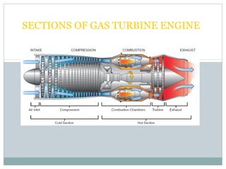
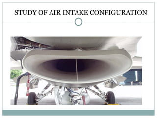
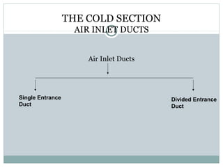
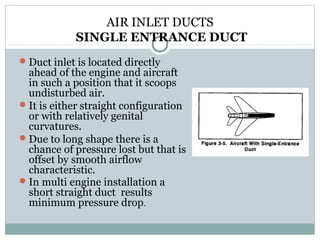
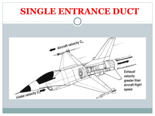
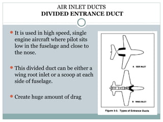
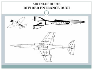
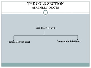
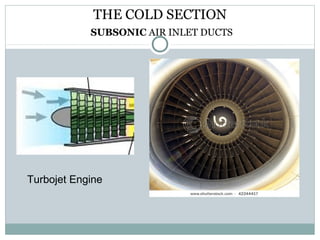
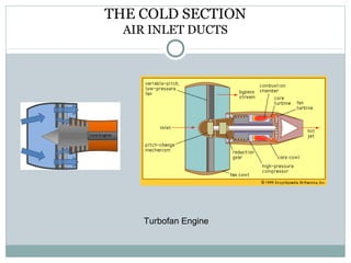
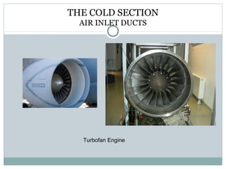
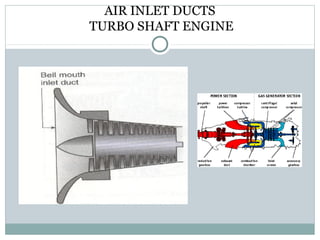
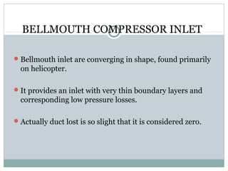
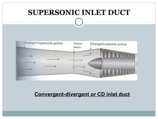
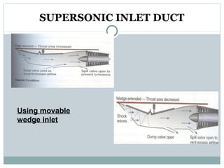
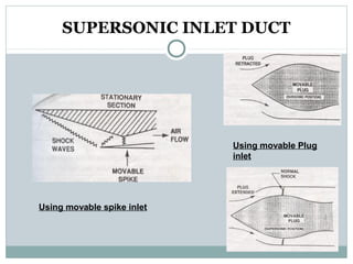
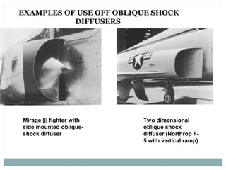
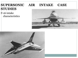
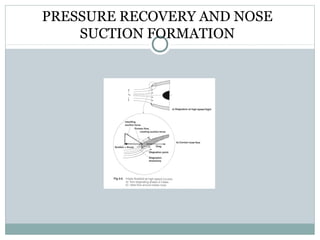
TURBINE ENGINE
 Aircraft Gas Turbine Power plants by Otis
 FAA 12A
 Aircraft Gas Turbine Engine Technology by Treager
 Aircraft Power plant by Kroes& Wild
 The Jet Engine by Rolls-Royce
TURBINE ENGINE
 Gas turbine engine are considered to be of two types:-

Gas turbine engine

Torque Producing
Engine

Thrust Producing
Engine

Turbojet
Engine

Turbofan
Engine

Turboprop
Engine

Turbo shaft
Engine
SECTIONS OF GAS TURBINE ENGINE
 An aircraft gas turbine engine is divided into two sections:


Cold section
Hot section

 The cold section contains:



Air Inlet Duct
Compressor
Diffuser

 The hot section contains:



Combustor
Turbine
Exhaust
ENGINE STATION DESIGNATION

To standardize the locations in gas turbine engines, a
numbering system has been devised that allows a person to
identify a location by numbers.
STUDY OF AIR INTAKE CONFIGURATION
NEED OF AIR INTAKE IN AN AIRCRAFT
• A widely used method to increase the thrust

generated by the aircraft engine is to increase
the air flow rate in the air intake by using
auxiliary air intake systems.

• The air flow enters the intake and is required

to reach the engine face with optimum levels
of total pressure and flow uniformity hence
need of an air intake system.

• Deceleration of airflow at high flight mach

numbers or aerodynamic compression with
help of air intake.
AIR INTAKE DESIGN REQUIREMENTS
• The air intake requires enormous effort properly to control
•
•
•

•
•

airflow to the engine.
The intake must be designed to provide the appropriate amount
of airflow required by the engine.
Furthermore this flow when leaving the intake section to enter the
compressor should be uniform stable and of high quality.
Good air intake design is therefore a prerequisite if installed
engine performance is to come close to performance figures
obtained at the static test bench.
The engine intake must be a low drag, light weight construction
,that is carefully and exactly manufactures.
These above conditions must be met not only during all phases of
flight but also on the ground with the aircraft at rest and the
engine demand maximum, thrust prior to take off
THE COLD SECTION
AIR INLET DUCTS
 The air inlet duct is technically a part of the airframe, but

it is so important in the development of thrust that it is
included with the engine as a part of the clod section.

 The air inlet duct must supply uniform flow of air to the

compressor so that it can operate stall free.

 It must produce as little drag as possible.
 If taken only a small obstruction to the air flow inside the

duct to cause a significant loss of efficiency.

 Inlet cover must be installed to prevent damage or

corrosion in this vital area.
THE COLD SECTION
AIR INLET DUCTS
Air Inlet Ducts

Single Entrance
Duct

Divided Entrance
Duct
AIR INLET DUCTS
SINGLE ENTRANCE DUCT
 Duct inlet is located directly

ahead of the engine and aircraft
in such a position that it scoops
undisturbed air.
 It is either straight configuration
or with relatively genital
curvatures.
 Due to long shape there is a
chance of pressure lost but that is
offset by smooth airflow
characteristic.
 In multi engine installation a
short straight duct results
minimum pressure drop.
SINGLE ENTRANCE DUCT
AIR INLET DUCTS
DIVIDED ENTRANCE DUCT
 It is used in high speed, single

engine aircraft where pilot sits
low in the fuselage and close to
the nose.
 This divided duct can be either a

wing root inlet or a scoop at each
side of fuselage.
 Create huge amount of drag
AIR INLET DUCTS
DIVIDED ENTRANCE DUCT
THE COLD SECTION
AIR INLET DUCTS

Air Inlet Ducts

Subsonic Inlet Duct

Supersonic Inlet Duct
THE COLD SECTION
SUBSONIC AIR INLET DUCTS
 The inlet duct is used in the multiengine subsonic aircraft is a fix

geometry duct whose diameter progressively increases from the front
to back. It is diverging duct and is also called an inlet diffuser
because of the effect, it has the effect on the pressure of the air
entering the engine.
 As air enters the inlet at ambient pressure it beguns to defuse, or
spread out, and by the time it arrives at the inlet to the compressor
its pressure is slightly higher than the ambient pressure.
 Usually the air diffuses in the front portion the duct and than it
progresses along at a fairly constant pressure passes the engine inlet
fairing and then into the compressor. This allows the engine to
receive the air with less turbulence and at a more uniform pressure.
THE COLD SECTION
SUBSONIC AIR INLET DUCTS

Turbojet Engine
THE COLD SECTION
AIR INLET DUCTS

Turbofan Engine
THE COLD SECTION
AIR INLET DUCTS

Turbofan Engine
AIR INLET DUCTS
TURBOPROP ENGINE

The propeller reduction gears are located at the front of the engine and
thus interfere with a smooth flow of air entering the compressor.
Generally 3 types of inlet duct is used:i) Ducted spinner inlet ii) Conical spinner inlet iii) Under scoop inlet
AIR INLET DUCTS
TURBOPROP ENGINE
AIR INLET DUCTS
TURBO SHAFT ENGINE
BELLMOUTH COMPRESSOR INLET
 Bellmouth inlet are converging in shape, found primarily

on helicopter.
 It provides an inlet with very thin boundary layers and

corresponding low pressure losses.
 Actually duct lost is so slight that it is considered zero.
SUPERSONIC INLET DUCT
 The air approaching the compressor inlet must always be at speed

below the speed of sound.
 when an aircraft is flying at supersonic speed, the inlet air must be

slowed down to subsonic speed before it reaches the compressor. This
is done by :

Using a convergent-divergent or CD inlet duct



Raising a Wedge or Spike or Plug inlet
SUPERSONIC INLET DUCT

Convergent-divergent or CD inlet duct
SUPERSONIC INLET DUCT

Using movable
wedge inlet
FLOW CONDITIONS OVER WEDGE AND CONE
In the design of supersonic air intakes flow conditions over
wedge and cone are of the greatest importance as these are
simple geometric bodies and relatively easy to manufacture.
COMPARISON OF SUPERSONIC FLOW
OVER CONE AND WEDGE
The major advantage of a (supersonic) conical flow is a smaller total pressure
loss (when compared to a wedge of the same half-angle), together with the
fact that a conical shock sustains lower mach numbers until it becomes
detached to form a high loss bow shock.
A major disadvantage of conical flows is that it is less tolerant to asymmetric
flow conditions which cause distortion to the intake flow. As combat aircraft
are frequently required to maneuver at higher angles of attack, the flow
inevitably gets asymmetric- hence a performance for the (horizontally
arranged) wedge in all modern combat aircraft, despite its reduced
efficiency.
SUPERSONIC INLET DUCT

Using movable Plug
inlet

Using movable spike inlet
EXAMPLES OF USE OFF OBLIQUE SHOCK
DIFFUSERS

Mirage ||| fighter with
side mounted obliqueshock diffuser

Two dimensional
oblique shock
diffuser (Northrop F5 with vertical ramp)
SUPERSONIC
STUDIES
F-16 intake
characteristics

AIR

INTAKE

CASE
SUPERSONIC INLET DUCT
 Inlet Buzz: The buzz is an airflow instability which occur when a shock wave is

alternately slowed and irregular flow occur at the inlet.
 In increasing condition it can cause violent fluctuations in pressure

through the inlet, which occur when a shock wave is alternately
swallowed and regulate by the inlet.
 This condition also cause damage to the inlet structure or possibly to

engine itself.
 A suitable variable geometry duct is used to eliminate the buzz by

increasing of airflow within the inlet duct.
INTAKE CONFIGURATION AND
OPERATION
Present-day turbine aero engines require subsonic flow at the entry to
the compressor, even if the aircraft is flying at supersonic speed. The
task of air intake is therefore to decelerate the supersonic external
flow to a subsonic speed acceptable to the compressor. As intake
discharge mach number are required to be in range of mach 0.4 to
0.7 great care must be exercised when decelerating the flow in order
to keep total pressure losses to a minimum .
Normal shock diffuser
For aircraft operating at a maximum speed equivalent to mach 1.5 a
normal shock diffuser is generally sufficient to decelerate
the supersonic airflow efficiently to the speed needed by
the compressor.
NACA SUBMERGED INLET IN A EURO
FIGHTER

The NACA submerged type intake is not very efficient for use with propulsion
installations. However, they are frequently used as intakes of auxiliary
systems (auxiliary power unit, heating and avionics bay cooling) as seen in
Fig above
Various types of
supersonic inlets
RAM RECOVERY
 When a turbine engine is operated there is a negative

pressure in the inlet because of the high velocity of the
airflow. As the aircraft moves forward in the flight, air
rams in to the inlet duct and ram recovery takes place.
This ram pressure rise cancel the pressure drops due to
friction inside the duct and the inlet pressure return to
ambient. Ram recovery occur above about 160 miles/hrs
or 0.1 mach to 0.2 mach in most of the aircraft.
 From this point the pressure continue to increases with
aircraft speed and additional thrust is created by the
engine with less expenditure of fuel.
PRESSURE RECOVERY AND NOSE
SUCTION FORMATION
BLOW-IN -DOOR
 It is used to prevent compressor stall.
 It is installed in the side of inlet duct and are spring loaded

to hold them closed.
 But when the inlet pressure becomes a specified amount

lower than that of the ambient air, the pressure differential
forces then open and furnishes additional air to the
compressor inlet.

turbine engine intake

  • 1.
    TURBINE ENGINE  AircraftGas Turbine Power plants by Otis  FAA 12A  Aircraft Gas Turbine Engine Technology by Treager  Aircraft Power plant by Kroes& Wild  The Jet Engine by Rolls-Royce
  • 2.
    TURBINE ENGINE  Gasturbine engine are considered to be of two types:- Gas turbine engine Torque Producing Engine Thrust Producing Engine Turbojet Engine Turbofan Engine Turboprop Engine Turbo shaft Engine
  • 3.
    SECTIONS OF GASTURBINE ENGINE
  • 4.
    SECTIONS OF GASTURBINE ENGINE  An aircraft gas turbine engine is divided into two sections:  Cold section Hot section  The cold section contains:   Air Inlet Duct Compressor Diffuser  The hot section contains:   Combustor Turbine Exhaust
  • 5.
    ENGINE STATION DESIGNATION Tostandardize the locations in gas turbine engines, a numbering system has been devised that allows a person to identify a location by numbers.
  • 6.
    STUDY OF AIRINTAKE CONFIGURATION
  • 7.
    NEED OF AIRINTAKE IN AN AIRCRAFT • A widely used method to increase the thrust generated by the aircraft engine is to increase the air flow rate in the air intake by using auxiliary air intake systems. • The air flow enters the intake and is required to reach the engine face with optimum levels of total pressure and flow uniformity hence need of an air intake system. • Deceleration of airflow at high flight mach numbers or aerodynamic compression with help of air intake.
  • 8.
    AIR INTAKE DESIGNREQUIREMENTS • The air intake requires enormous effort properly to control • • • • • airflow to the engine. The intake must be designed to provide the appropriate amount of airflow required by the engine. Furthermore this flow when leaving the intake section to enter the compressor should be uniform stable and of high quality. Good air intake design is therefore a prerequisite if installed engine performance is to come close to performance figures obtained at the static test bench. The engine intake must be a low drag, light weight construction ,that is carefully and exactly manufactures. These above conditions must be met not only during all phases of flight but also on the ground with the aircraft at rest and the engine demand maximum, thrust prior to take off
  • 9.
    THE COLD SECTION AIRINLET DUCTS  The air inlet duct is technically a part of the airframe, but it is so important in the development of thrust that it is included with the engine as a part of the clod section.  The air inlet duct must supply uniform flow of air to the compressor so that it can operate stall free.  It must produce as little drag as possible.  If taken only a small obstruction to the air flow inside the duct to cause a significant loss of efficiency.  Inlet cover must be installed to prevent damage or corrosion in this vital area.
  • 10.
    THE COLD SECTION AIRINLET DUCTS Air Inlet Ducts Single Entrance Duct Divided Entrance Duct
  • 11.
    AIR INLET DUCTS SINGLEENTRANCE DUCT  Duct inlet is located directly ahead of the engine and aircraft in such a position that it scoops undisturbed air.  It is either straight configuration or with relatively genital curvatures.  Due to long shape there is a chance of pressure lost but that is offset by smooth airflow characteristic.  In multi engine installation a short straight duct results minimum pressure drop.
  • 12.
  • 13.
    AIR INLET DUCTS DIVIDEDENTRANCE DUCT  It is used in high speed, single engine aircraft where pilot sits low in the fuselage and close to the nose.  This divided duct can be either a wing root inlet or a scoop at each side of fuselage.  Create huge amount of drag
  • 14.
  • 15.
    THE COLD SECTION AIRINLET DUCTS Air Inlet Ducts Subsonic Inlet Duct Supersonic Inlet Duct
  • 16.
    THE COLD SECTION SUBSONICAIR INLET DUCTS  The inlet duct is used in the multiengine subsonic aircraft is a fix geometry duct whose diameter progressively increases from the front to back. It is diverging duct and is also called an inlet diffuser because of the effect, it has the effect on the pressure of the air entering the engine.  As air enters the inlet at ambient pressure it beguns to defuse, or spread out, and by the time it arrives at the inlet to the compressor its pressure is slightly higher than the ambient pressure.  Usually the air diffuses in the front portion the duct and than it progresses along at a fairly constant pressure passes the engine inlet fairing and then into the compressor. This allows the engine to receive the air with less turbulence and at a more uniform pressure.
  • 17.
    THE COLD SECTION SUBSONICAIR INLET DUCTS Turbojet Engine
  • 18.
    THE COLD SECTION AIRINLET DUCTS Turbofan Engine
  • 19.
    THE COLD SECTION AIRINLET DUCTS Turbofan Engine
  • 20.
    AIR INLET DUCTS TURBOPROPENGINE The propeller reduction gears are located at the front of the engine and thus interfere with a smooth flow of air entering the compressor. Generally 3 types of inlet duct is used:i) Ducted spinner inlet ii) Conical spinner inlet iii) Under scoop inlet
  • 21.
  • 22.
  • 23.
    BELLMOUTH COMPRESSOR INLET Bellmouth inlet are converging in shape, found primarily on helicopter.  It provides an inlet with very thin boundary layers and corresponding low pressure losses.  Actually duct lost is so slight that it is considered zero.
  • 24.
    SUPERSONIC INLET DUCT The air approaching the compressor inlet must always be at speed below the speed of sound.  when an aircraft is flying at supersonic speed, the inlet air must be slowed down to subsonic speed before it reaches the compressor. This is done by : Using a convergent-divergent or CD inlet duct  Raising a Wedge or Spike or Plug inlet
  • 25.
  • 26.
    SUPERSONIC INLET DUCT Usingmovable wedge inlet
  • 27.
    FLOW CONDITIONS OVERWEDGE AND CONE In the design of supersonic air intakes flow conditions over wedge and cone are of the greatest importance as these are simple geometric bodies and relatively easy to manufacture.
  • 28.
    COMPARISON OF SUPERSONICFLOW OVER CONE AND WEDGE The major advantage of a (supersonic) conical flow is a smaller total pressure loss (when compared to a wedge of the same half-angle), together with the fact that a conical shock sustains lower mach numbers until it becomes detached to form a high loss bow shock. A major disadvantage of conical flows is that it is less tolerant to asymmetric flow conditions which cause distortion to the intake flow. As combat aircraft are frequently required to maneuver at higher angles of attack, the flow inevitably gets asymmetric- hence a performance for the (horizontally arranged) wedge in all modern combat aircraft, despite its reduced efficiency.
  • 30.
    SUPERSONIC INLET DUCT Usingmovable Plug inlet Using movable spike inlet
  • 31.
    EXAMPLES OF USEOFF OBLIQUE SHOCK DIFFUSERS Mirage ||| fighter with side mounted obliqueshock diffuser Two dimensional oblique shock diffuser (Northrop F5 with vertical ramp)
  • 32.
  • 33.
    SUPERSONIC INLET DUCT Inlet Buzz: The buzz is an airflow instability which occur when a shock wave is alternately slowed and irregular flow occur at the inlet.  In increasing condition it can cause violent fluctuations in pressure through the inlet, which occur when a shock wave is alternately swallowed and regulate by the inlet.  This condition also cause damage to the inlet structure or possibly to engine itself.  A suitable variable geometry duct is used to eliminate the buzz by increasing of airflow within the inlet duct.
  • 34.
    INTAKE CONFIGURATION AND OPERATION Present-dayturbine aero engines require subsonic flow at the entry to the compressor, even if the aircraft is flying at supersonic speed. The task of air intake is therefore to decelerate the supersonic external flow to a subsonic speed acceptable to the compressor. As intake discharge mach number are required to be in range of mach 0.4 to 0.7 great care must be exercised when decelerating the flow in order to keep total pressure losses to a minimum . Normal shock diffuser For aircraft operating at a maximum speed equivalent to mach 1.5 a normal shock diffuser is generally sufficient to decelerate the supersonic airflow efficiently to the speed needed by the compressor.
  • 35.
    NACA SUBMERGED INLETIN A EURO FIGHTER The NACA submerged type intake is not very efficient for use with propulsion installations. However, they are frequently used as intakes of auxiliary systems (auxiliary power unit, heating and avionics bay cooling) as seen in Fig above
  • 36.
  • 37.
    RAM RECOVERY  Whena turbine engine is operated there is a negative pressure in the inlet because of the high velocity of the airflow. As the aircraft moves forward in the flight, air rams in to the inlet duct and ram recovery takes place. This ram pressure rise cancel the pressure drops due to friction inside the duct and the inlet pressure return to ambient. Ram recovery occur above about 160 miles/hrs or 0.1 mach to 0.2 mach in most of the aircraft.  From this point the pressure continue to increases with aircraft speed and additional thrust is created by the engine with less expenditure of fuel.
  • 38.
    PRESSURE RECOVERY ANDNOSE SUCTION FORMATION
  • 39.
    BLOW-IN -DOOR  Itis used to prevent compressor stall.  It is installed in the side of inlet duct and are spring loaded to hold them closed.  But when the inlet pressure becomes a specified amount lower than that of the ambient air, the pressure differential forces then open and furnishes additional air to the compressor inlet.