Download as PDF, PPTX
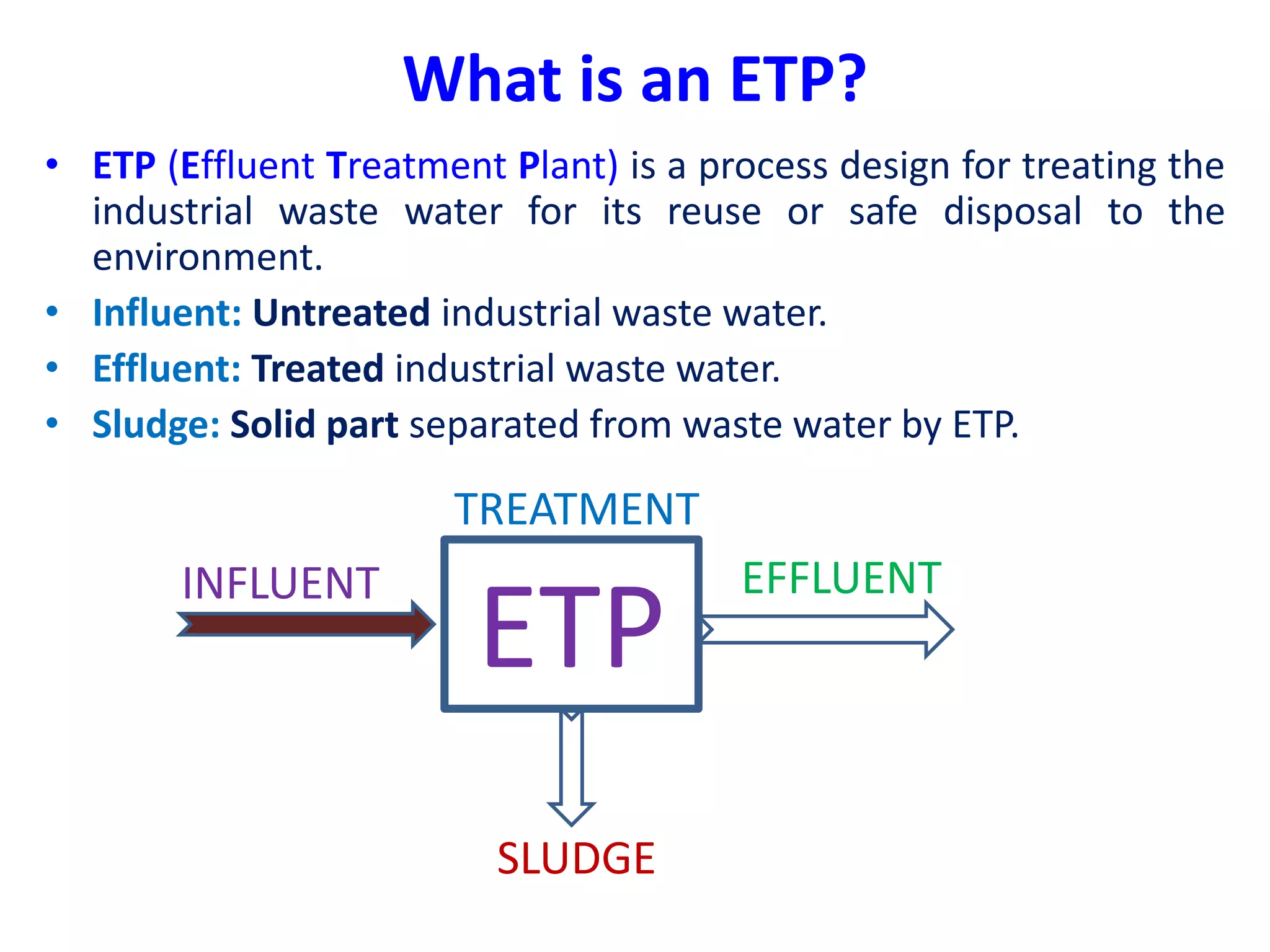

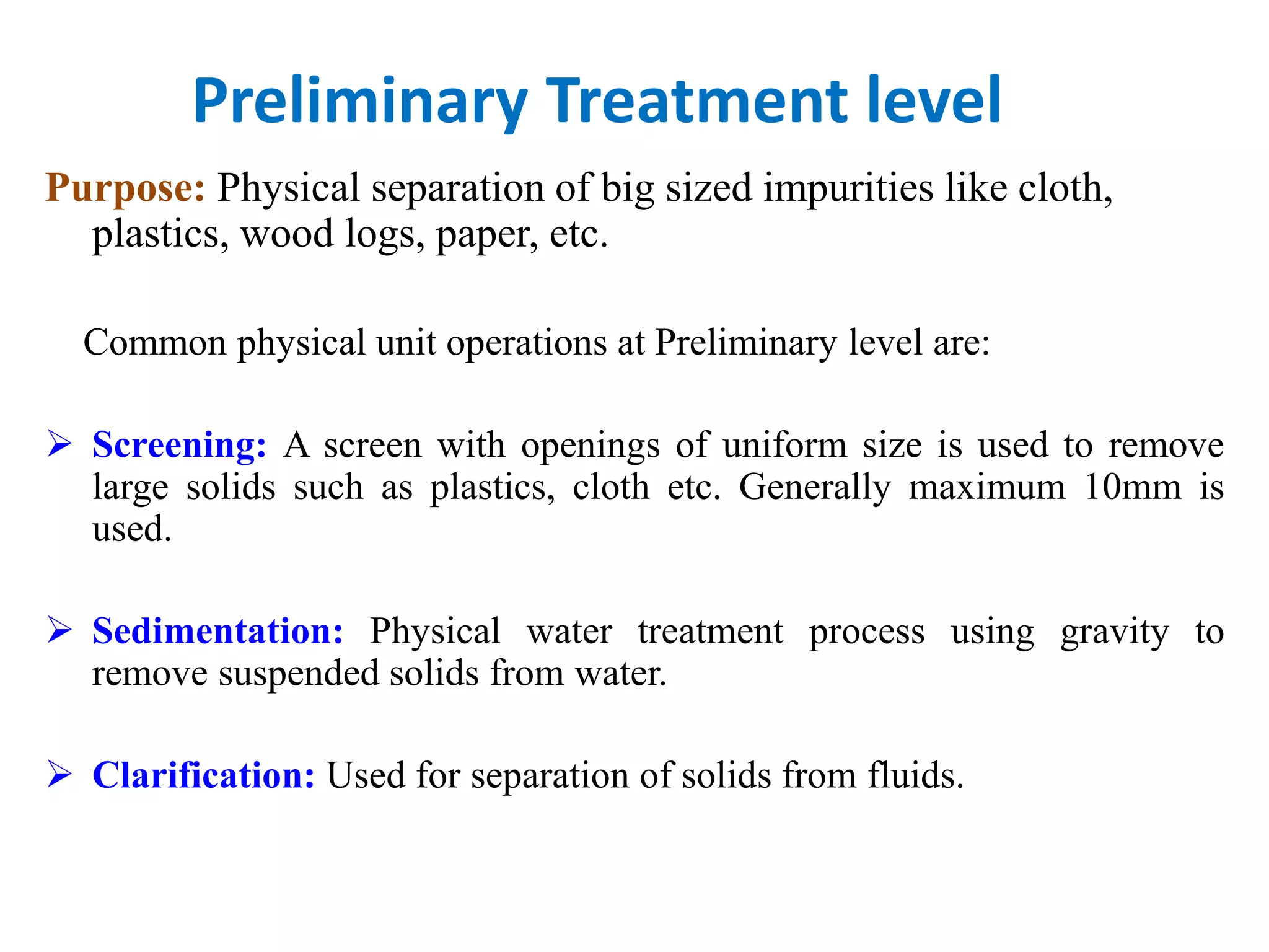


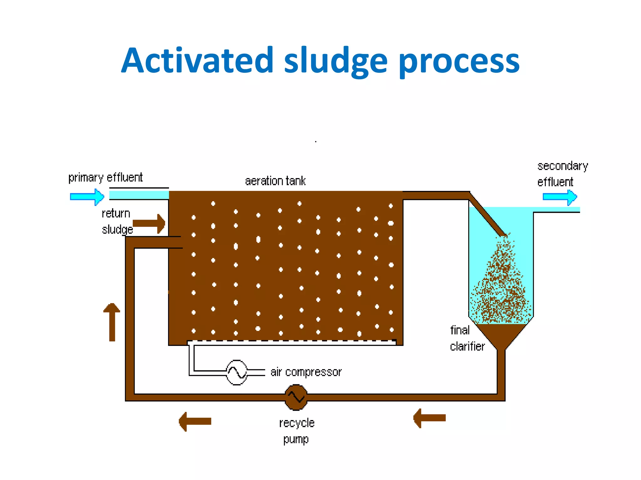


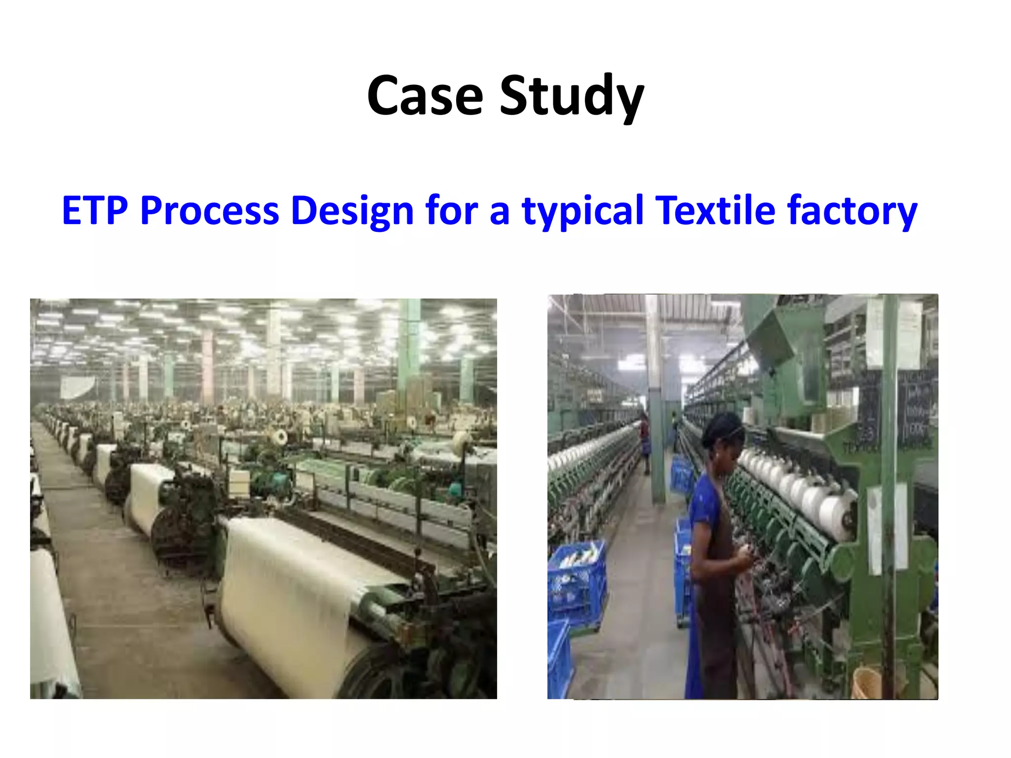
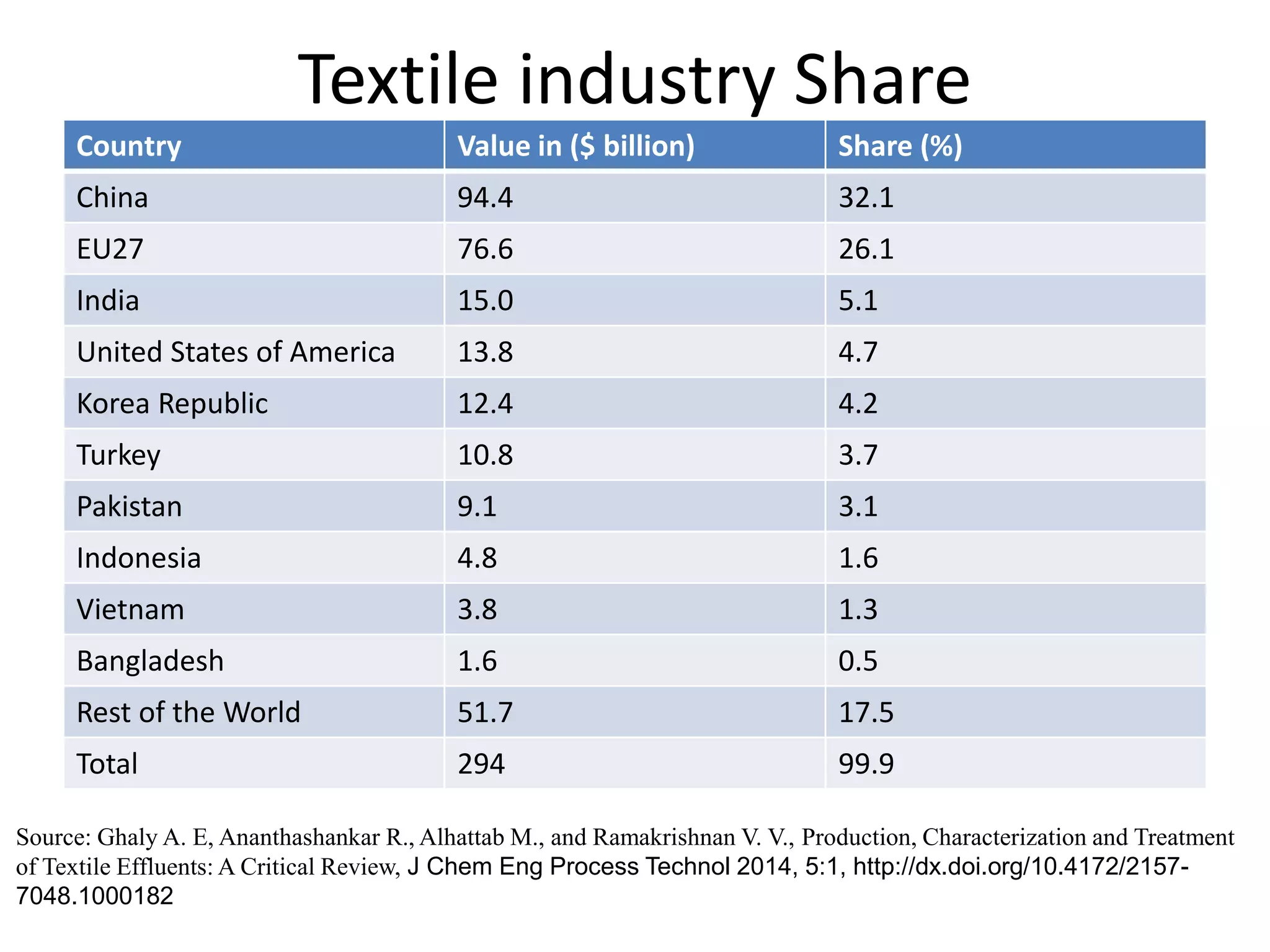


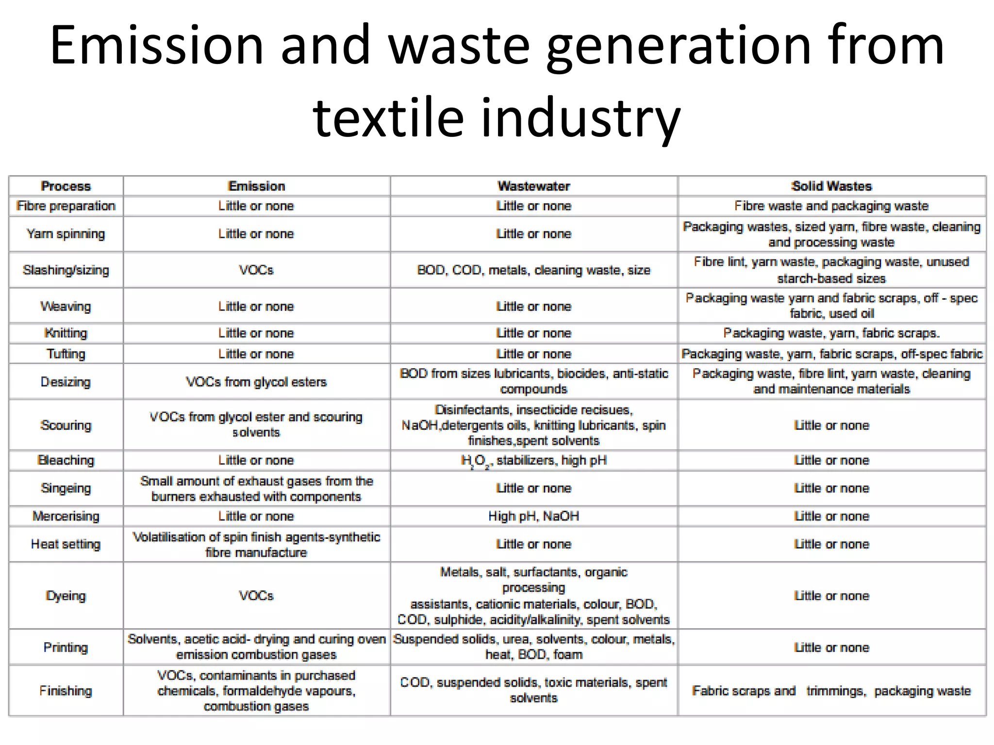


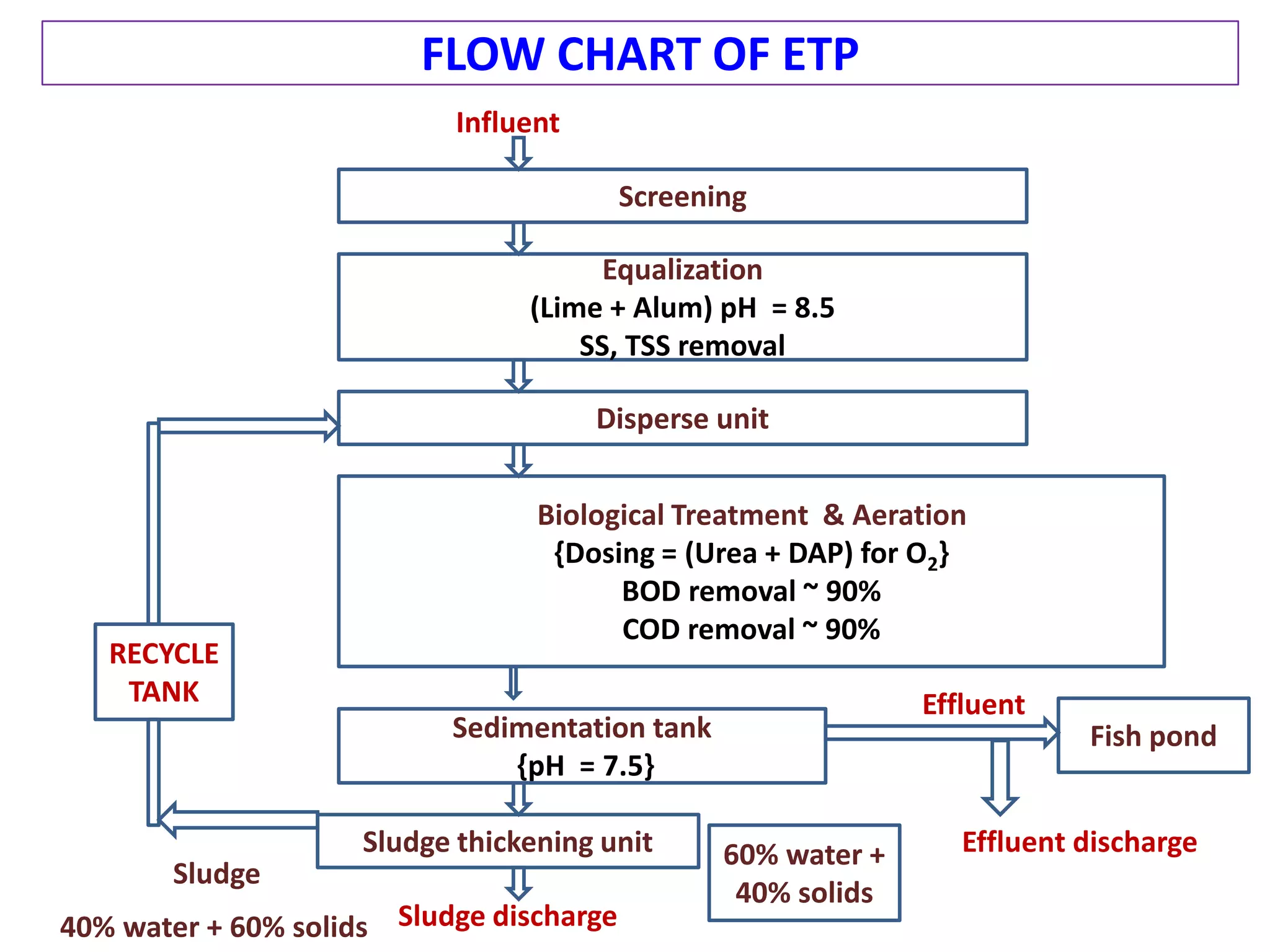


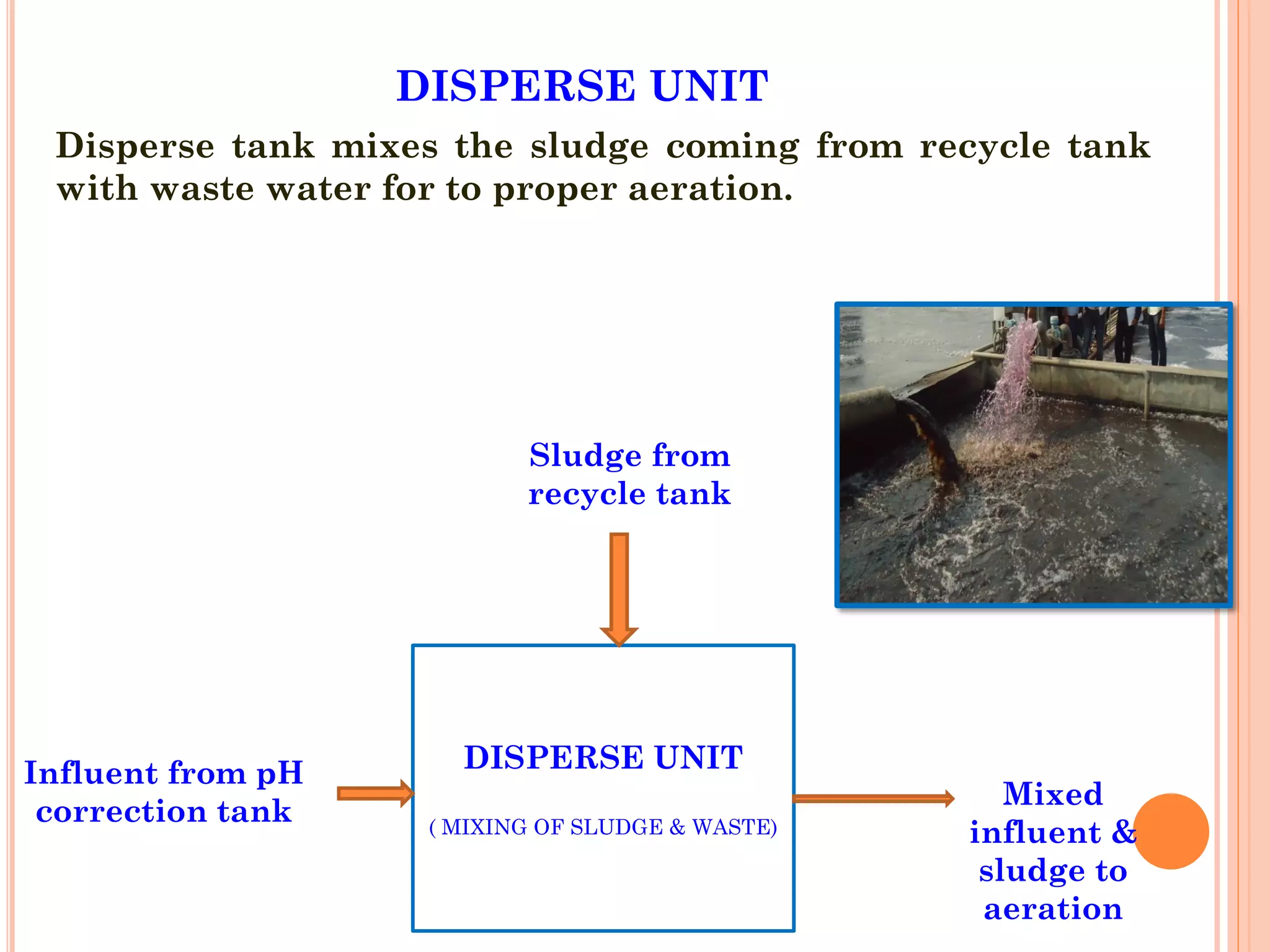
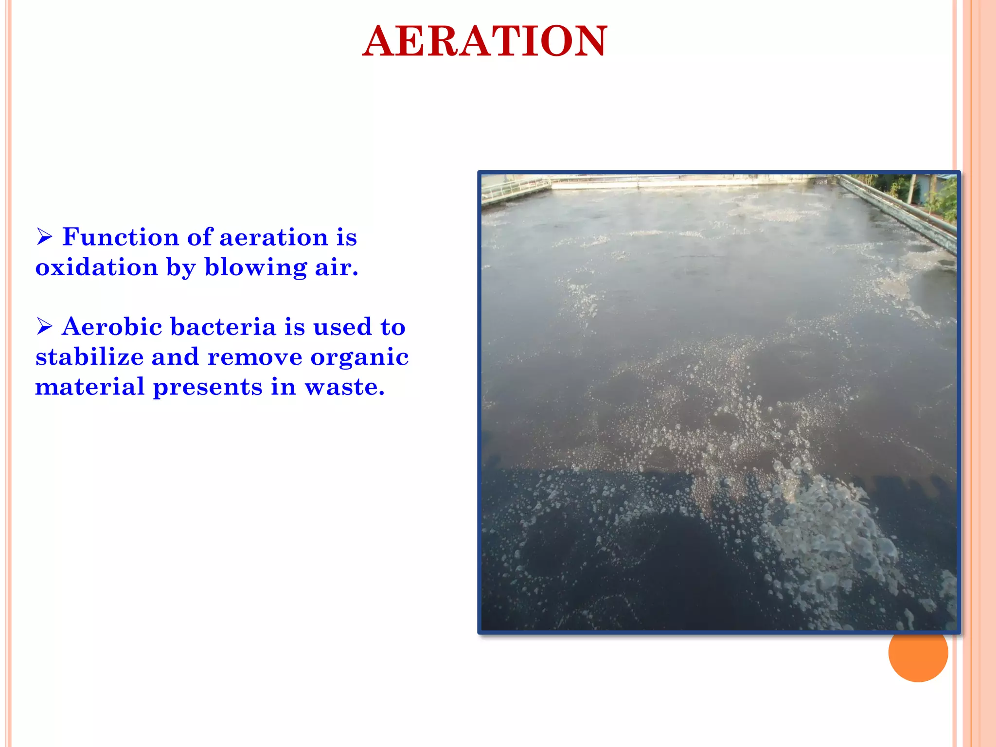
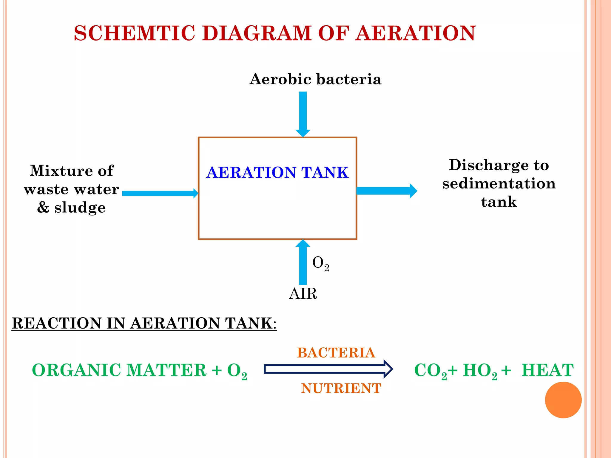


The document provides an overview of effluent treatment plants (ETPs), outlining their purpose, design, treatment levels, and mechanisms used for treating industrial wastewater, particularly in the textile industry. It discusses the importance of recycling water to reduce fresh water usage and comply with environmental standards. The document details the various phases of wastewater treatment from preliminary to tertiary levels, including processes such as screening, sedimentation, biological treatment, and advanced methods for improving water quality before discharge.


