Download to read offline
![2
Introduction:
Effluent is the stream of excess chemical liquor from an industry after using in original
operation. For example, the excess dye liquor extracted from the textile industry after dyeing
is an effluent of that dyeing industry. Effluent Treatment Plant or ETP is a waste water
treatment method which is particularly designed to purify industrial waste water for its reuse
and it’s aim is to release safe water to environment from the harmful effect caused by the
effluent. Textile industry uses numerous hazardous chemicals during processing such as heavy
metals, salts, surfactants, sulphite, and formaldehyde, which can cause major pollution in the
effluents’ receiving waters. Since textile waste water contains a diversity of impurities and
therefore specific treatment technology called ETP is required. The ETP Plant works at various
levels and involves various physical, chemical, biological and membrane processes to treat
waste water from different industrial sectors like chemicals, drugs, pharmaceutical, refineries,
dairy, ready mix plants & textile etc.
CHAREACTERISTICS OF PROCESS WASTE WATER OF TEXTILE PROCESSING
INDUSTRIES [1]:
Unit process Possible pollutants in the waste water Nature of the waste water
Desizing Starch, glucose, CMC, PVA, resin, fats
and waxes.
High BOD (35-50% of total)
Scouring NaOH, waxes, greases, Na2CO3 and
fragments of cloth.
Strongly alkaline weak color.
High BOD (30% of total)
Bleaching Na(OCl),Cl2, NaOH, H2O2, acid etc. Alkaline 5% of total BOD
Mercerisation NaOH Strongly alkaline low BOD
(less than 1%)
Dyeing Various dyes, salts, alkali, acid, Na2S,
Na2S2O4 and soaps, detergent etc.
Strongly colored fairly BOD
(6% of the total)
Printing Colors, starch, china clay, gum, oil,
mordents, acid, alkali, various metallic
salts etc.
Highly colored and oily
appearance BOD, (6-10% of
total)](https://image.slidesharecdn.com/etpplant-211203033929/75/Plan-an-ETP-with-detail-process-discussion-following-the-instructions-2-2048.jpg)
![3
Finishing Traces of starch, tallow and different
finishing agents.
Low BOD (2-4% of total)
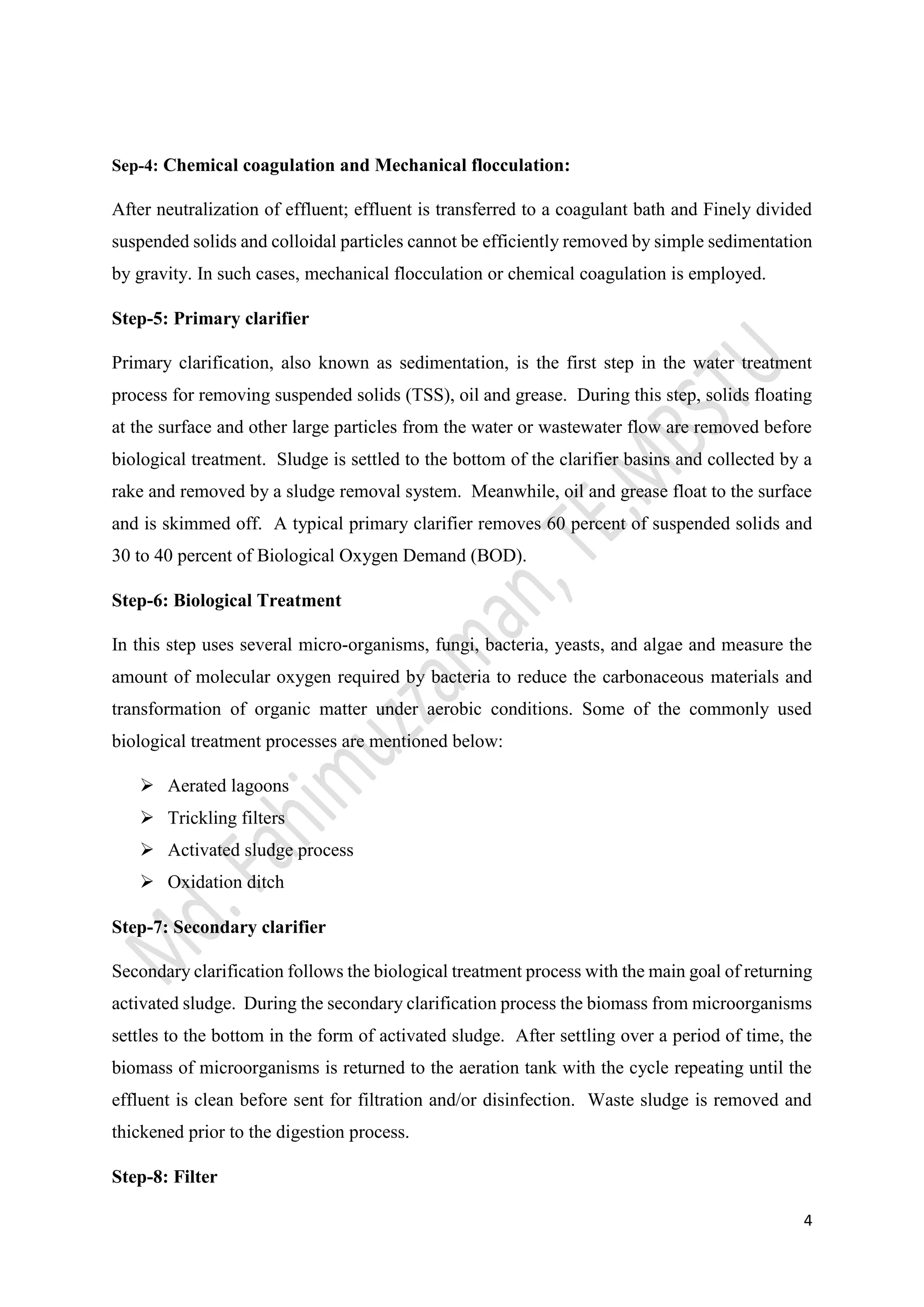
Schematic diagram of Effluent Treatment Plant [2]
Step-1: Primary Filtration
It is the first stage of effluent treatment plant, where effluent is come from weav-ing, dyeing,
printing or finishing unit. Here primary filtration is performed to remove the Coarse suspended
matters such as rags, pieces of fabric, fibres, yarns and lint are removed. Bar screens and
mechanically cleaned fine screens remove most of the fibres..
Step-2: Cooling and mixing
In this stage, different types of effluent are mixed and cool down by rotating agitators or by blowing
compressed air from below.
Step-3: Neutralization by Acid/Alkali Dossing
Most of the effluent are alkaline some are acidic acidic which are comes from dyeing section. After
cooling and mixing; effluent is transferred to neutralization tank by the help of pump. Here, acid or
alkali is mixed to neutralize the effluent. A pH meter is placed in the neutralization tank.](https://image.slidesharecdn.com/etpplant-211203033929/75/Plan-an-ETP-with-detail-process-discussion-following-the-instructions-3-2048.jpg)
![5
After completing all process before discharging drain final filtration done here and separate the
sludge and water.
Step-9: Discharge to drain
After completion of all the process, the effluent becomes purify and it becomes safe to drain to
the environment.
INTERNATIONAL STANDARD OF EFFLUENT FOR DISCHARGE TO DRAIN[1]:
Serial No Characteristics Average quantity of
the effluent
Required limit to
discharge
01 BOD 250-500 mg/L 20-40 mg/L
02 COD 800-1200 mg/L 120-160 mg/L
03 Suspended solid 200-300 mg/L 20-40 mg/L
04 Settle able solid 0-5 mg/L Traces
05 Ammonia 20-30 mg/L 4-8 mg/L
06 Phosphate 3-5 mg/L 3-5 mg/L
07 Surfactant 30-40 mg/L 0.5-2 mg/L
08 Chloride 1000-1500 mg/L 1000-1500 mg/L
09 Sulphate 1000-1500 mg/L 1000-1500 mg/L
10 Color Colored Not perceptible
11 Oil and fat 30-40 mg/L < 5 mg/L
12 Phenol 3-5 mg/L < 0.05 mg/L
13 Temp. 45-0
500
C ≥450
C
Conclusion:
Effluent Treatment Plant (ETP) is essential to purify the waste water which is come from different stage
of textile industry like weaving, knitting, Scouring, bleaching, dyeing, finishing etc. It consists several
steps which sued to reduce hazardous effect by subsequent primary, secondary and tertiary treatment.](https://image.slidesharecdn.com/etpplant-211203033929/75/Plan-an-ETP-with-detail-process-discussion-following-the-instructions-5-2048.jpg)
![6
Primary treatment used to remove of a portion of the suspended solids and organic matter from
wastewater, Removal of biodegradable organic matter and suspended solids uses secondary
treatment alt last uses tertiary and advanced treatment for reuses of waste water. It is necessary
for all manufacturing industry to build a properly active ETP plant to safe our Environment.
References
[1] A. A. Mamun, “Study materials,” 2016.
[2] A. katiyar, “Working Procedure Of Effluent TreatmentPlant (ETP),” Textile Fashion Study, 2012.](https://image.slidesharecdn.com/etpplant-211203033929/75/Plan-an-ETP-with-detail-process-discussion-following-the-instructions-6-2048.jpg)

The document discusses the characteristics and treatment of wastewater from the textile industry, emphasizing the importance of effluent treatment plants (ETPs) to purify industrial wastewater for environmental safety. It outlines the various steps involved in the ETP process, including primary filtration, neutralization, chemical coagulation, biological treatment, and final filtration before discharge. International standards for the permissible limits of various pollutants in effluents are also provided to ensure safe discharge into the environment.


