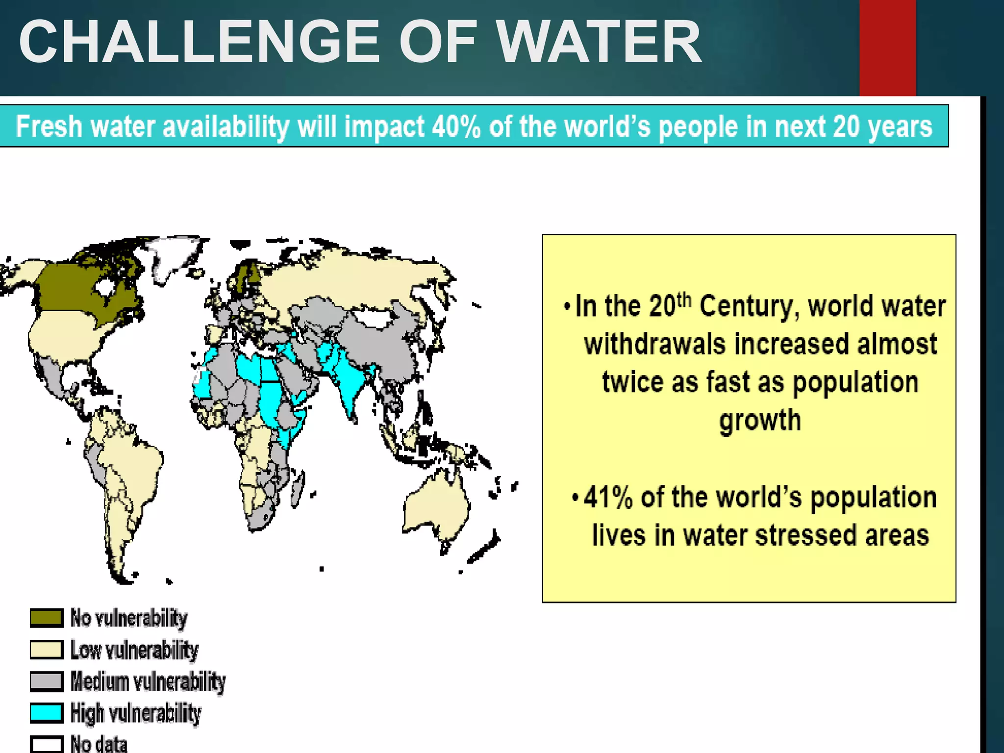
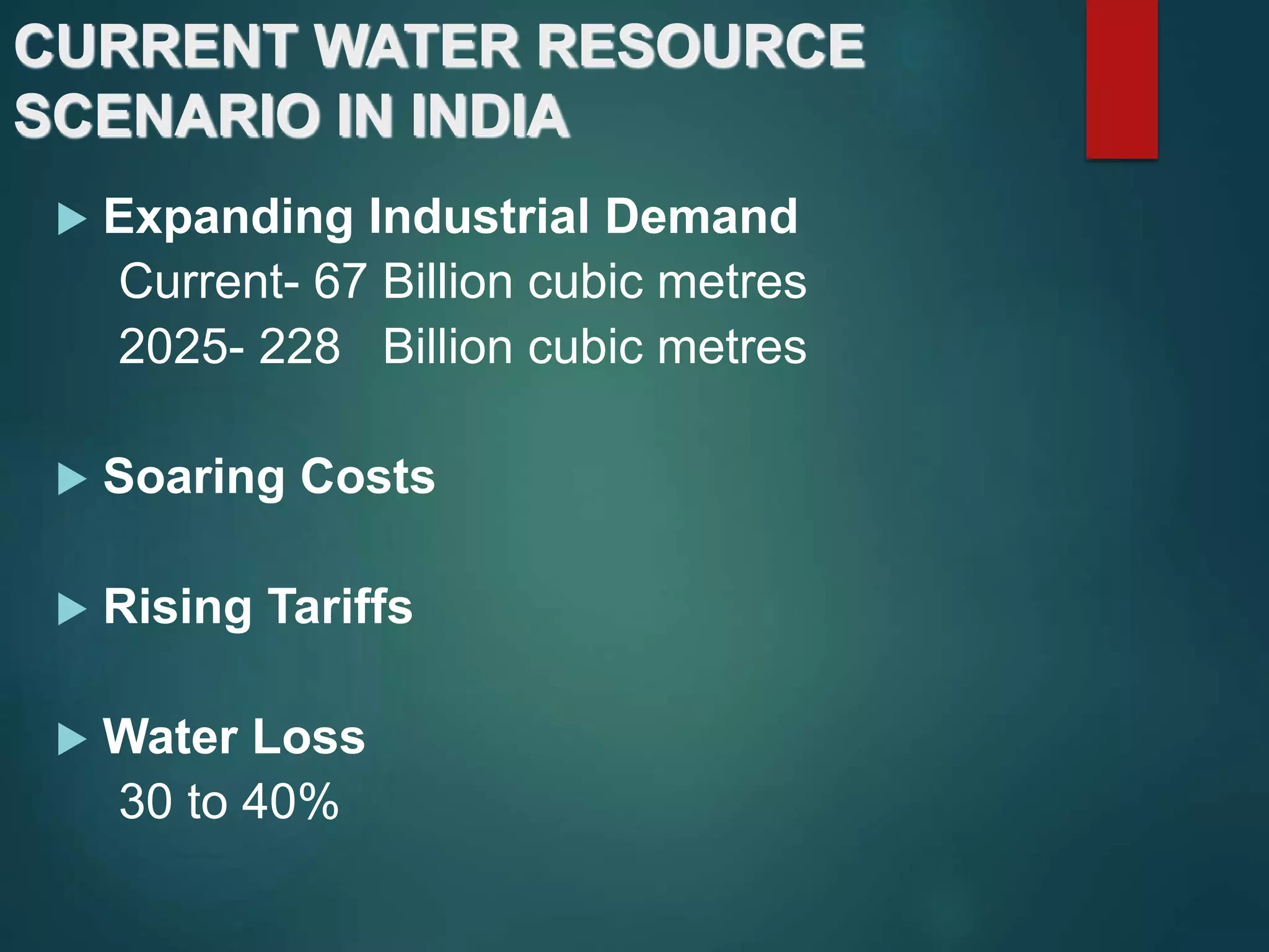
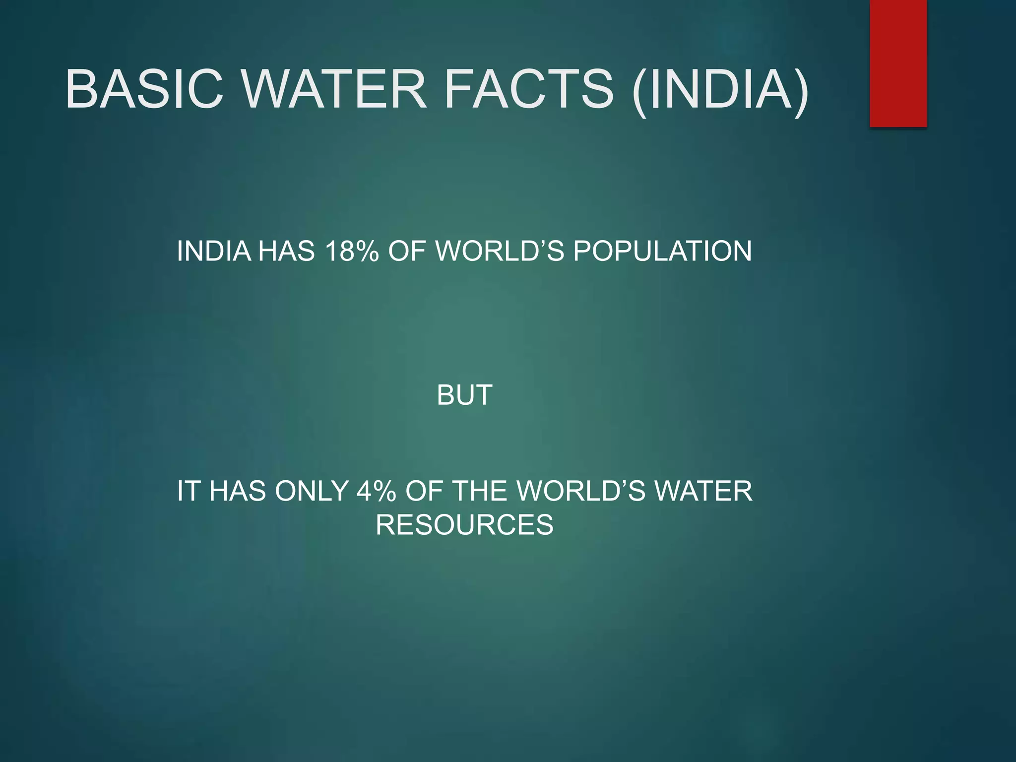
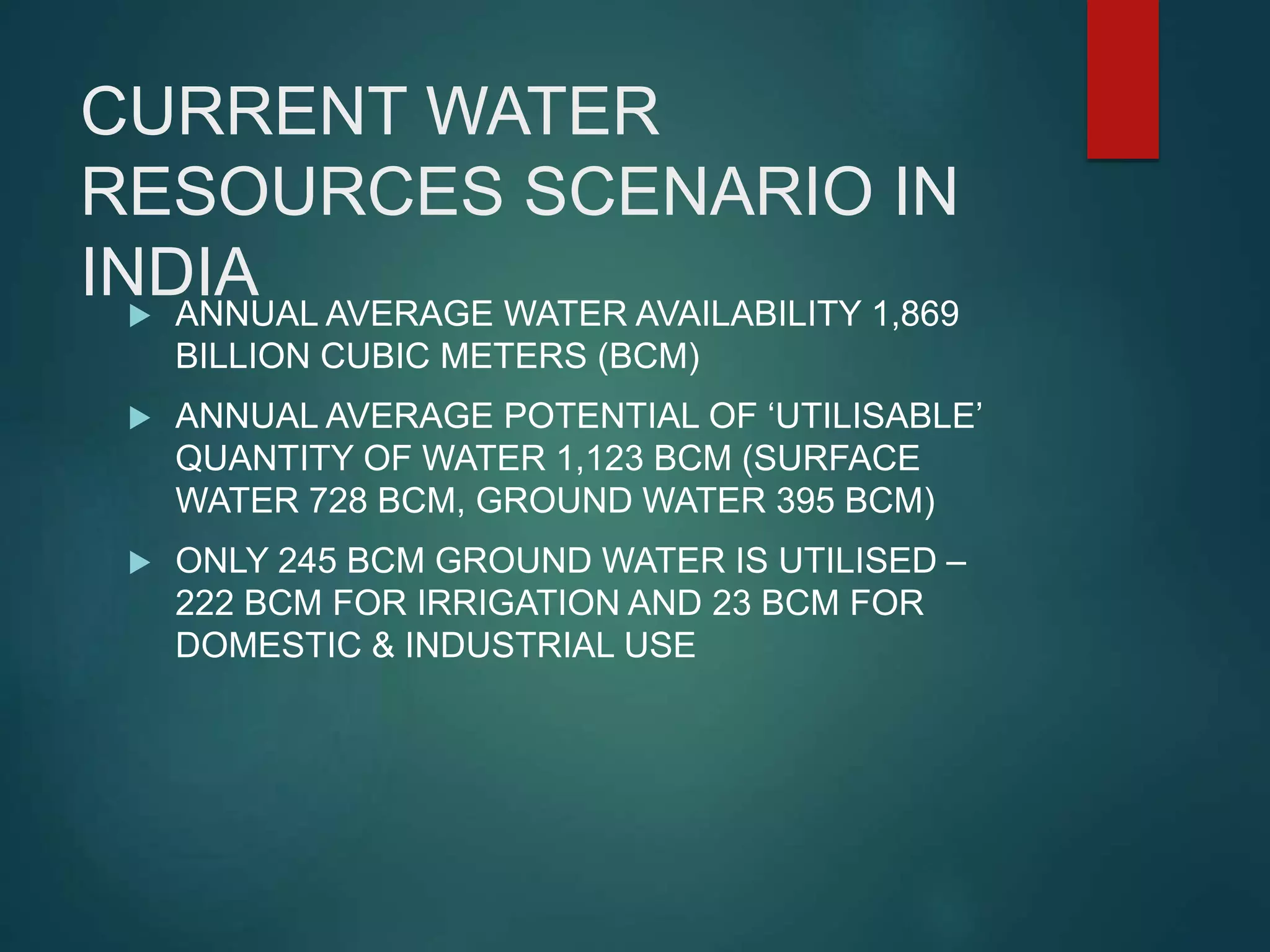
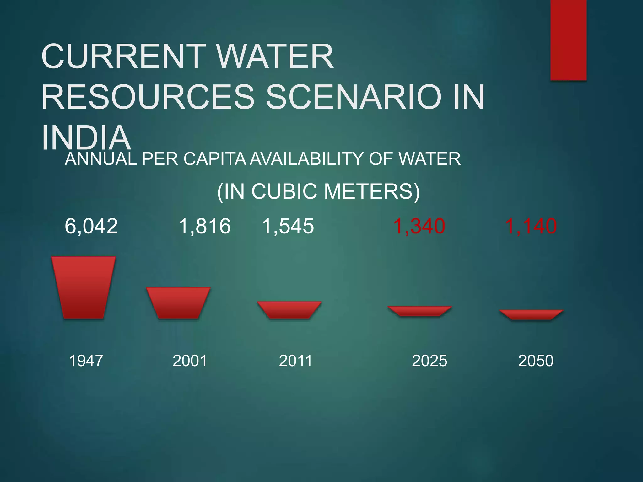
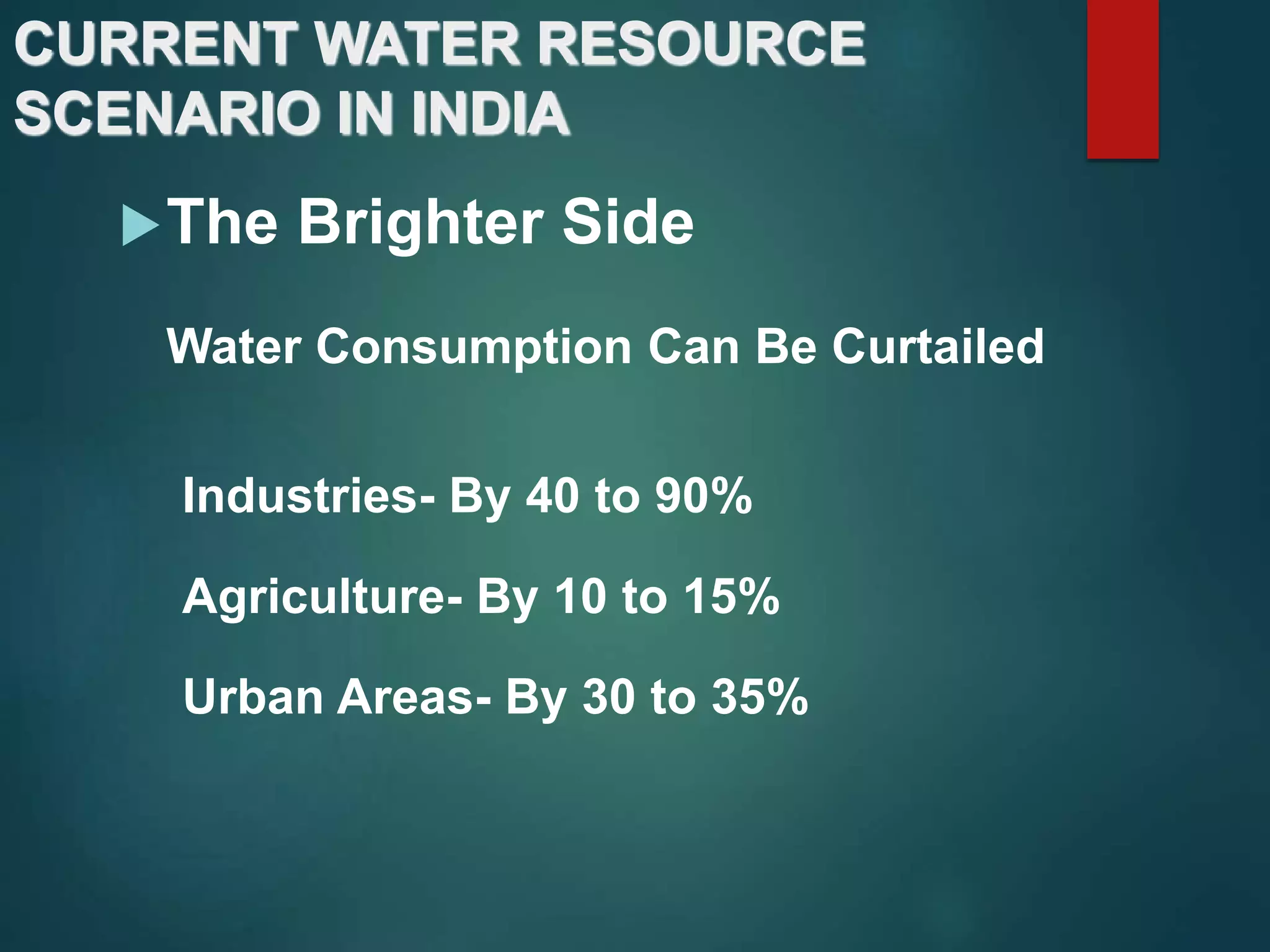
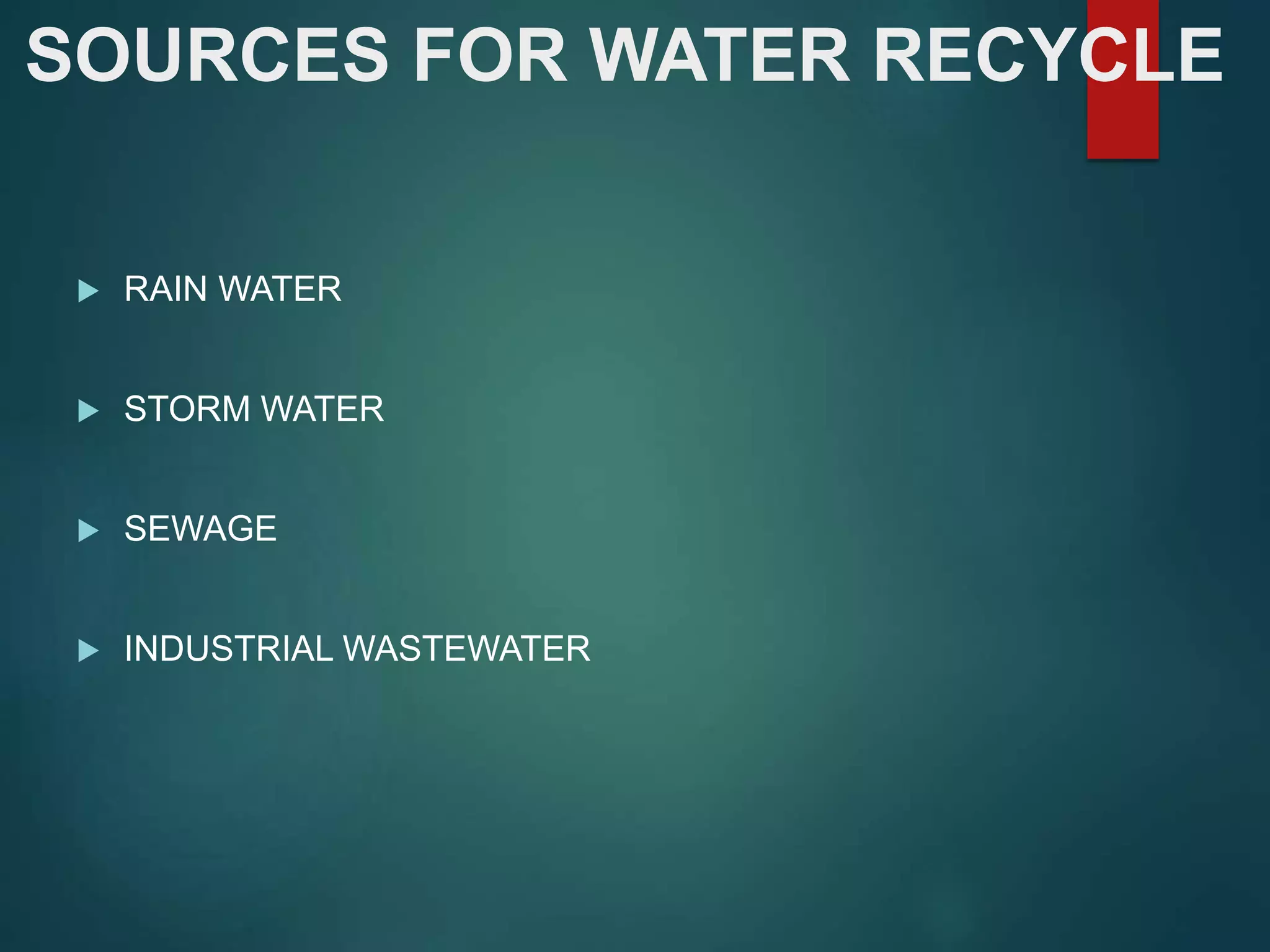
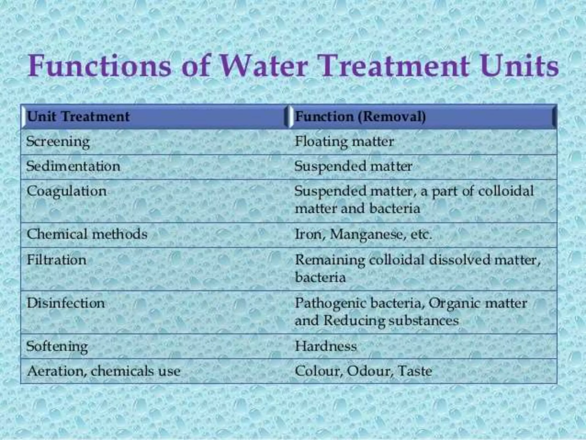
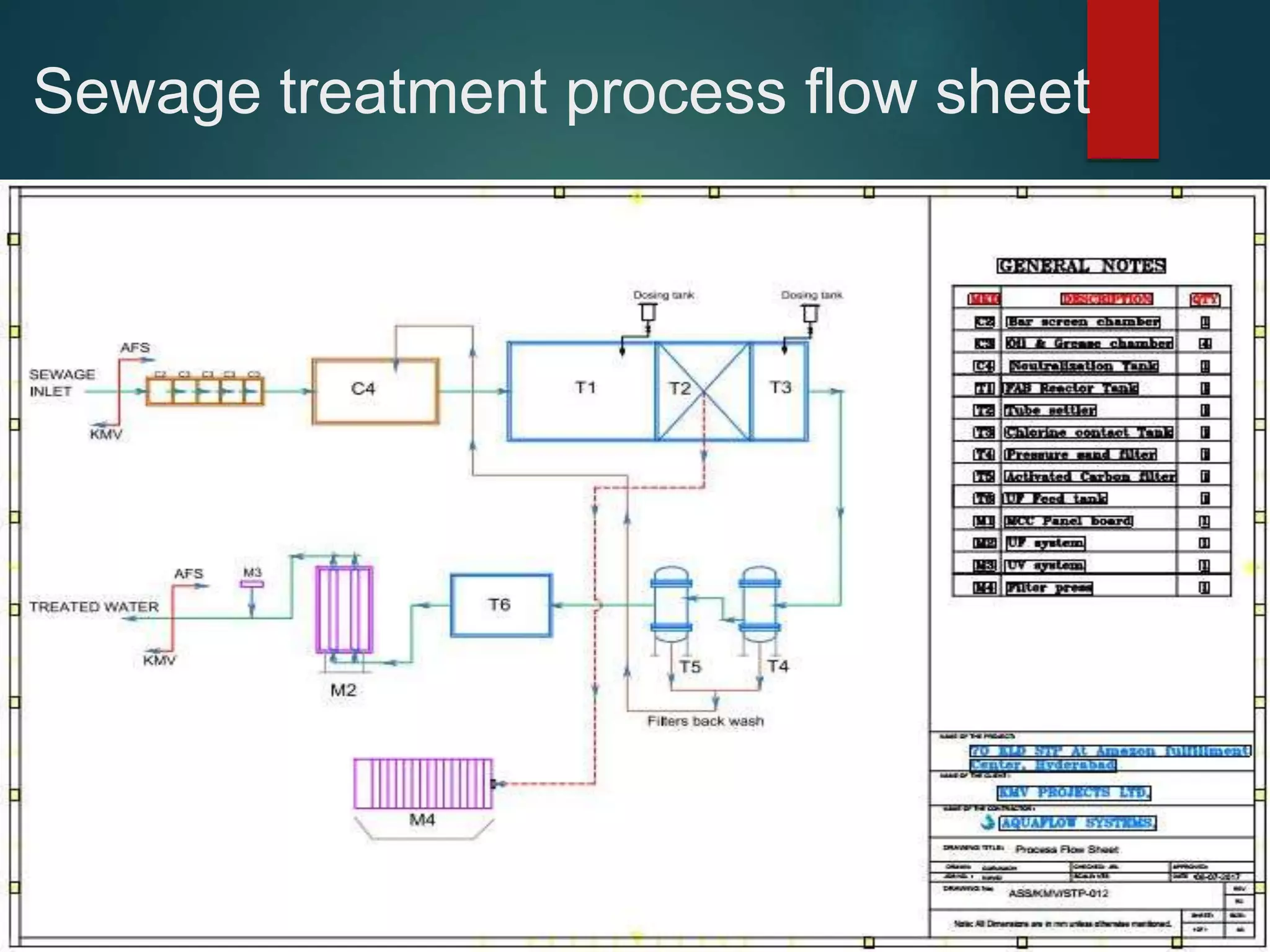
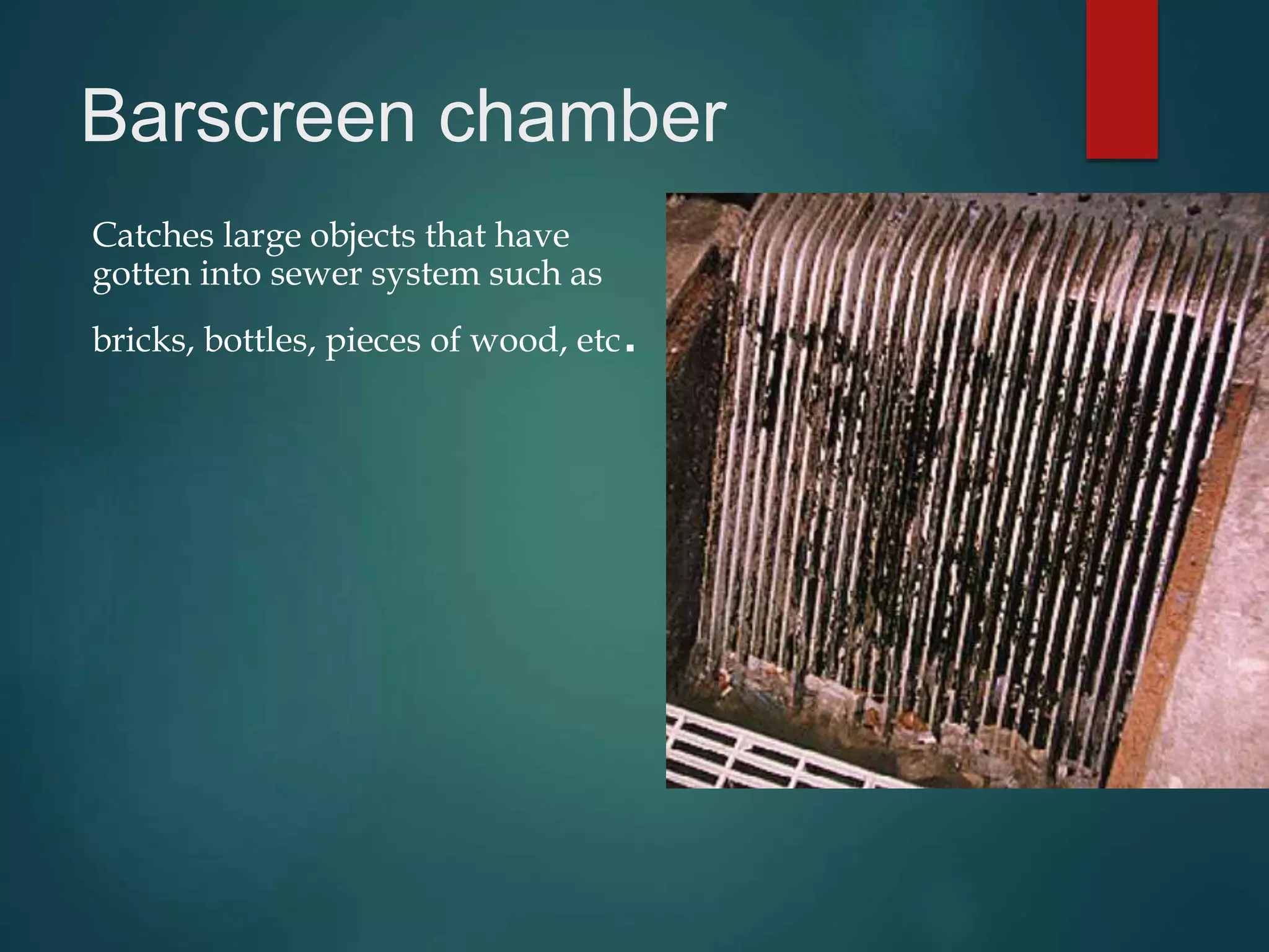
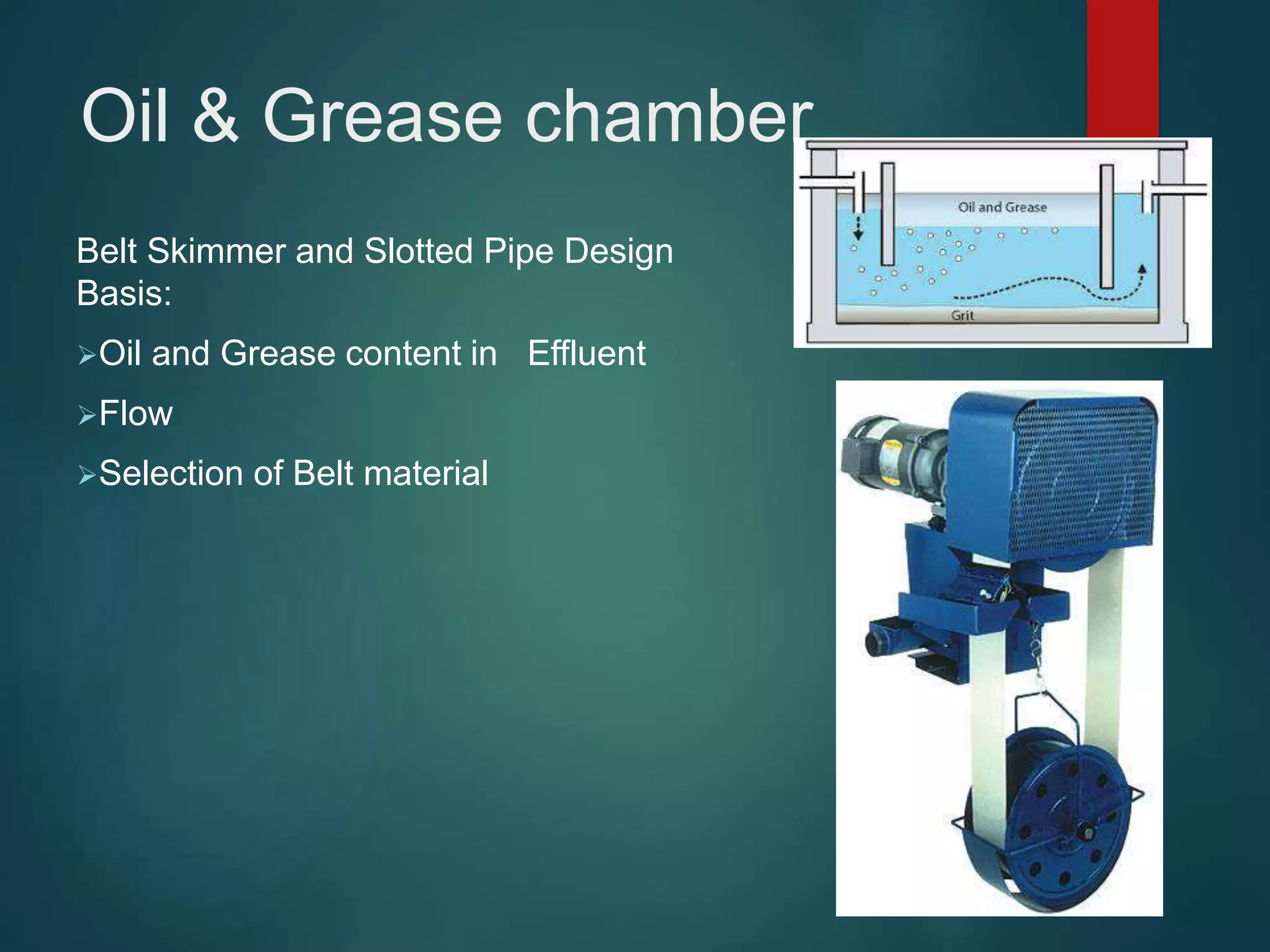
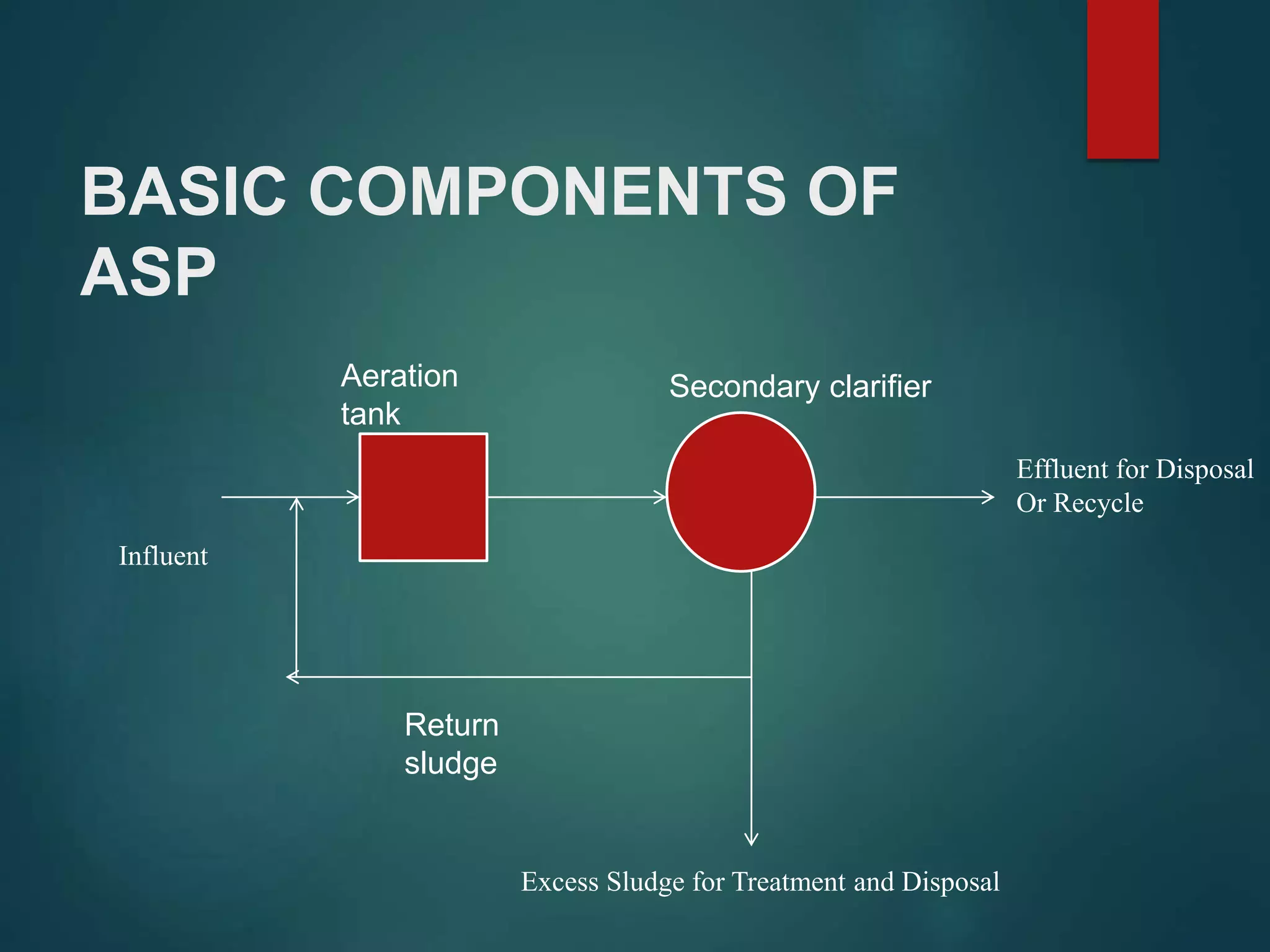
IMPORTANCE OF WATER
AND STP OPERATION &
MAINTENANCE
AQUAFLOW SYSTEMS
HYDERABAD
NOVEMBER 28, 2018
TRAINER: MR. RAJENDRA PRASAD VELLANKI
MR. PRAVEEN KUMAR MANCHUKONDA
INTRODUCTIONS
 SELF INTRODUCTIONS
- Qualifications
- Experience
- Role in Organisation
- Objectives for this
Training Program
RULES
 Always Pay Attention to Safety
 Phones : Switch off / Silent Mode
 Participation : Active, Feel Free to Ask
 Breaks : Lunch & Tea/Coffee Breaks
WATER CRISIS
• GLOBAL
• QUANTITY & QUALITY
 INAPPROPRIATE USE OF SURFACE WATER
RESOURCES
 CHANGE IN HYDROLOGICAL CYCLE DUE TO
HUMAN INTERVENTION
 OVER EXPLOITATION OF GROUNDWATER
 WATER WASTAGE AND POLLUTION
REASONS FOR WATER CRISIS
CHALLENGE OF WATER
CURRENT WATER RESOURCE
SCENARIO IN INDIA
 Expanding Industrial Demand
Current- 67 Billion cubic metres
2025- 228 Billion cubic metres
 Soaring Costs
 Rising Tariffs
 Water Loss
30 to 40%
BASIC WATER FACTS (INDIA)
INDIA HAS 18% OF WORLD’S POPULATION
BUT
IT HAS ONLY 4% OF THE WORLD’S WATER
RESOURCES
CURRENT WATER
RESOURCES SCENARIO IN
INDIA ANNUAL AVERAGE WATER AVAILABILITY 1,869
BILLION CUBIC METERS (BCM)
 ANNUAL AVERAGE POTENTIAL OF ‘UTILISABLE’
QUANTITY OF WATER 1,123 BCM (SURFACE
WATER 728 BCM, GROUND WATER 395 BCM)
 ONLY 245 BCM GROUND WATER IS UTILISED –
222 BCM FOR IRRIGATION AND 23 BCM FOR
DOMESTIC & INDUSTRIAL USE
CURRENT WATER
RESOURCES SCENARIO IN
INDIAANNUAL PER CAPITA AVAILABILITY OF WATER
(IN CUBIC METERS)
6,042 1,816 1,545 1,340 1,140
1947 2001 2011 2025 2050
CURRENT WATER RESOURCE
SCENARIO IN INDIA
The Brighter Side
Water Consumption Can Be Curtailed
Industries- By 40 to 90%
Agriculture- By 10 to 15%
Urban Areas- By 30 to 35%
SOME SOLUTIONS
 JUDICIOUS USE OF AVAILABLE WATER RESOURCES
 POLLUTION PREVENTION
 USE OF ALTERNATE SOURCES LIKE SEA WATER, GRAY
WATER, RECYCLED SEWAGE,ETC.
 WATER HARVESTING
SOURCES FOR WATER RECYCLE
 RAIN WATER
 STORM WATER
 SEWAGE
 INDUSTRIAL WASTEWATER
SOURCE QUALITY
 RAIN WATER – PURE UNCONTAMINATED
 STORM WATER – LOW CONTAMINATION
Suspended Solids
Oil & Grease
Agricultural Runoffs
Chemicals
SOURCE QUALITY
 SEWAGE – LOW TO MEDIUM CONTAMINATION
Physical
Organic
SOURCE QUALITY
 INDUSTRIAL WASTEWATER
- MEDIUM TO VERY HIGH CONTAMINATION
Physical
Chemical
Organic
WASTE MANAGEMENT HIERARCHY
 Cleaner Production / Waste Minimisation
 Treatment
 Reuse / Recover / Recycle
 Disposal
Sewage treatment
 Purpose:
To manage water discharged from homes, hospital,
hotels and apartments to reduce the threat of water
pollution.
SOURCES OF SEWAGE
 Domestic waste from industries
 Apartments
 Resorts
 Hospitals and Hotels
Sewage treatment
processes
Preliminary Treatment
Secondary Treatment
Tertiary Treatment
These treatments are classified as
 Physical treatment – preliminary treatment
 Biological treatment – secondary treatment
Sewage treatment process flow sheet
Barscreen chamber
Catches large objects that have
gotten into sewer system such as
bricks, bottles, pieces of wood, etc.
Oil & Grease chamber
Belt Skimmer and Slotted Pipe Design
Basis:
Oil and Grease content in Effluent
Flow
Selection of Belt material
Neutralization tank
Purpose:
to neutralize the collected sample for below
reasons.
 A pH range of 6.0 to 8.5 is most suited to provide
protection to aquatic life
 pH affects the solubility of organic matter and
availability of BOD
 pH affects the toxicity levels of metals
FAB REACTOR TANK
(FLUIDIZED AIR BED
REACTOR TANK)
Purpose:
 The removal of
Organic matter (BOD/COD)
Suspended solids
Nitrates & Phosphates
Pathogens
FAB REACTOR TANK
(FLUIDIZED AIR BED
REACTOR TANK)
Aerobic process:
 Microorganisms breakdown the organic matter in the
waste water and produce carbon dioxide + water +
sludge
 Aerobic reaction
Organic matter + O2 CO2 + H2O +
New cells
PRE CONDITIONS OF
AEROBIC TREATMENT
 Food for Bacteria (Organic matter / BOD)
 Oxygen
 Temperature
 TDS
 pH
 O & G
 Heavy metals / Toxic chemicals
 Nutrients
Activated sludge process
(ASP)
 Aerobic suspended growth process most widely used
 Process consists of Aeration Tank, Secondary Clarifier
and system for returning and wasting sludge.
 Sequencing Batch Reactor (SBR) and Membrane Bio-
Reactor (MBR) are fundamentally activated sludge
processes
Process design
considerations(ASP)
 Effluent Characteristics
 Selection of the reactor type
 Applicable kinetics relationships
 Solid retention time and loading criteria to be used
 Sludge production
 Oxygen requirement and transfer (Mixing energy)
 Nutrients requirements
 Other chemical requirements
 Settling characteristics
CONTROLLING
PARAMETERS – ASP
 Organic loading rate
 Oxygen supply
 Control and operation of the final settling tank
 Nutrient Availability (BOD:N:P: :100:5:1)
BASIC COMPONENTS OF
ASP
Influent
Aeration
tank
Secondary clarifier
Return
sludge
Effluent for Disposal
Or Recycle
Excess Sludge for Treatment and Disposal
Tube settler
Tube Settler Systems for
Clarification. Tube settler
parallel plates increase
the settling capacity of
circular clarifiers and/or
rectangular sedimentation
basins by reducing the
vertical distance a floc
particle must settle before
agglomerating to form
larger particles.
Pressure sand filter
Raw water is passed
through the pressure sand
filter, the filter media (Fine
quartz sand) is supported
on gravel & pebbles bed of
progressively larger sizes.
During the filtration cycle
the filter bed retains the
dirt and suspended
particles from the water
and accumulates within
the filter bed.
Activated carbon filter
 Carbon filtering is a method
of filtering that uses a bed of
activated carbon to remove
contaminants and impurities,
using chemical absorption.
Each particle/granule
of carbon provides a large
surface area/pore structure,
allowing contaminants the
maximum possible exposure to
the active sites within
the filter media.
ULTRAFILTRATION (UF)
MEMBRANES Membranes:
 Hollow Fibre capillary
 MOC : Poly Ether Sulphone (PES) or
PolyvinylideneFluoride (PVDF)
 Used as pre-treatment to RO
 Less pressure, less footprint area
UV SYSTEM
 An ultraviolet disinfection bank consists of
one or more UV lamps and a conduit or duct
in which the water or wastewater to be
irradiated flows. A UV light transparent
material separates the lamps from the
water/wastewater.
STP Operation Presentation

STP Operation Presentation

  • 1.
    IMPORTANCE OF WATER ANDSTP OPERATION & MAINTENANCE AQUAFLOW SYSTEMS HYDERABAD NOVEMBER 28, 2018 TRAINER: MR. RAJENDRA PRASAD VELLANKI MR. PRAVEEN KUMAR MANCHUKONDA
  • 2.
    INTRODUCTIONS  SELF INTRODUCTIONS -Qualifications - Experience - Role in Organisation - Objectives for this Training Program
  • 3.
    RULES  Always PayAttention to Safety  Phones : Switch off / Silent Mode  Participation : Active, Feel Free to Ask  Breaks : Lunch & Tea/Coffee Breaks
  • 4.
    WATER CRISIS • GLOBAL •QUANTITY & QUALITY
  • 5.
     INAPPROPRIATE USEOF SURFACE WATER RESOURCES  CHANGE IN HYDROLOGICAL CYCLE DUE TO HUMAN INTERVENTION  OVER EXPLOITATION OF GROUNDWATER  WATER WASTAGE AND POLLUTION REASONS FOR WATER CRISIS
  • 6.
  • 7.
    CURRENT WATER RESOURCE SCENARIOIN INDIA  Expanding Industrial Demand Current- 67 Billion cubic metres 2025- 228 Billion cubic metres  Soaring Costs  Rising Tariffs  Water Loss 30 to 40%
  • 8.
    BASIC WATER FACTS(INDIA) INDIA HAS 18% OF WORLD’S POPULATION BUT IT HAS ONLY 4% OF THE WORLD’S WATER RESOURCES
  • 9.
    CURRENT WATER RESOURCES SCENARIOIN INDIA ANNUAL AVERAGE WATER AVAILABILITY 1,869 BILLION CUBIC METERS (BCM)  ANNUAL AVERAGE POTENTIAL OF ‘UTILISABLE’ QUANTITY OF WATER 1,123 BCM (SURFACE WATER 728 BCM, GROUND WATER 395 BCM)  ONLY 245 BCM GROUND WATER IS UTILISED – 222 BCM FOR IRRIGATION AND 23 BCM FOR DOMESTIC & INDUSTRIAL USE
  • 10.
    CURRENT WATER RESOURCES SCENARIOIN INDIAANNUAL PER CAPITA AVAILABILITY OF WATER (IN CUBIC METERS) 6,042 1,816 1,545 1,340 1,140 1947 2001 2011 2025 2050
  • 11.
    CURRENT WATER RESOURCE SCENARIOIN INDIA The Brighter Side Water Consumption Can Be Curtailed Industries- By 40 to 90% Agriculture- By 10 to 15% Urban Areas- By 30 to 35%
  • 12.
    SOME SOLUTIONS  JUDICIOUSUSE OF AVAILABLE WATER RESOURCES  POLLUTION PREVENTION  USE OF ALTERNATE SOURCES LIKE SEA WATER, GRAY WATER, RECYCLED SEWAGE,ETC.  WATER HARVESTING
  • 13.
    SOURCES FOR WATERRECYCLE  RAIN WATER  STORM WATER  SEWAGE  INDUSTRIAL WASTEWATER
  • 14.
    SOURCE QUALITY  RAINWATER – PURE UNCONTAMINATED  STORM WATER – LOW CONTAMINATION Suspended Solids Oil & Grease Agricultural Runoffs Chemicals
  • 15.
    SOURCE QUALITY  SEWAGE– LOW TO MEDIUM CONTAMINATION Physical Organic
  • 16.
    SOURCE QUALITY  INDUSTRIALWASTEWATER - MEDIUM TO VERY HIGH CONTAMINATION Physical Chemical Organic
  • 17.
    WASTE MANAGEMENT HIERARCHY Cleaner Production / Waste Minimisation  Treatment  Reuse / Recover / Recycle  Disposal
  • 20.
    Sewage treatment  Purpose: Tomanage water discharged from homes, hospital, hotels and apartments to reduce the threat of water pollution.
  • 21.
    SOURCES OF SEWAGE Domestic waste from industries  Apartments  Resorts  Hospitals and Hotels
  • 22.
    Sewage treatment processes Preliminary Treatment SecondaryTreatment Tertiary Treatment These treatments are classified as  Physical treatment – preliminary treatment  Biological treatment – secondary treatment
  • 32.
  • 33.
    Barscreen chamber Catches largeobjects that have gotten into sewer system such as bricks, bottles, pieces of wood, etc.
  • 34.
    Oil & Greasechamber Belt Skimmer and Slotted Pipe Design Basis: Oil and Grease content in Effluent Flow Selection of Belt material
  • 35.
    Neutralization tank Purpose: to neutralizethe collected sample for below reasons.  A pH range of 6.0 to 8.5 is most suited to provide protection to aquatic life  pH affects the solubility of organic matter and availability of BOD  pH affects the toxicity levels of metals
  • 36.
    FAB REACTOR TANK (FLUIDIZEDAIR BED REACTOR TANK) Purpose:  The removal of Organic matter (BOD/COD) Suspended solids Nitrates & Phosphates Pathogens
  • 37.
    FAB REACTOR TANK (FLUIDIZEDAIR BED REACTOR TANK) Aerobic process:  Microorganisms breakdown the organic matter in the waste water and produce carbon dioxide + water + sludge  Aerobic reaction Organic matter + O2 CO2 + H2O + New cells
  • 38.
    PRE CONDITIONS OF AEROBICTREATMENT  Food for Bacteria (Organic matter / BOD)  Oxygen  Temperature  TDS  pH  O & G  Heavy metals / Toxic chemicals  Nutrients
  • 39.
    Activated sludge process (ASP) Aerobic suspended growth process most widely used  Process consists of Aeration Tank, Secondary Clarifier and system for returning and wasting sludge.  Sequencing Batch Reactor (SBR) and Membrane Bio- Reactor (MBR) are fundamentally activated sludge processes
  • 40.
    Process design considerations(ASP)  EffluentCharacteristics  Selection of the reactor type  Applicable kinetics relationships  Solid retention time and loading criteria to be used  Sludge production  Oxygen requirement and transfer (Mixing energy)  Nutrients requirements  Other chemical requirements  Settling characteristics
  • 41.
    CONTROLLING PARAMETERS – ASP Organic loading rate  Oxygen supply  Control and operation of the final settling tank  Nutrient Availability (BOD:N:P: :100:5:1)
  • 42.
    BASIC COMPONENTS OF ASP Influent Aeration tank Secondaryclarifier Return sludge Effluent for Disposal Or Recycle Excess Sludge for Treatment and Disposal
  • 43.
    Tube settler Tube SettlerSystems for Clarification. Tube settler parallel plates increase the settling capacity of circular clarifiers and/or rectangular sedimentation basins by reducing the vertical distance a floc particle must settle before agglomerating to form larger particles.
  • 44.
    Pressure sand filter Rawwater is passed through the pressure sand filter, the filter media (Fine quartz sand) is supported on gravel & pebbles bed of progressively larger sizes. During the filtration cycle the filter bed retains the dirt and suspended particles from the water and accumulates within the filter bed.
  • 45.
    Activated carbon filter Carbon filtering is a method of filtering that uses a bed of activated carbon to remove contaminants and impurities, using chemical absorption. Each particle/granule of carbon provides a large surface area/pore structure, allowing contaminants the maximum possible exposure to the active sites within the filter media.
  • 46.
    ULTRAFILTRATION (UF) MEMBRANES Membranes: Hollow Fibre capillary  MOC : Poly Ether Sulphone (PES) or PolyvinylideneFluoride (PVDF)  Used as pre-treatment to RO  Less pressure, less footprint area
  • 47.
    UV SYSTEM  Anultraviolet disinfection bank consists of one or more UV lamps and a conduit or duct in which the water or wastewater to be irradiated flows. A UV light transparent material separates the lamps from the water/wastewater.