U6000 power 73385 fuel cells_version1_e
•
2 likes•624 views

PEM fuel cells show outstanding advantages for air-independent propulsion on submarines. Siemens has developed 30-40kW and 120kW PEM fuel cell modules that have been installed on German submarines of the U212A and planned for the U214 class. The fuel cell modules generate electric power through a chemical reaction between hydrogen and oxygen with high efficiency and no pollutant emissions.

Recommended
Recommended
More Related Content
What's hot
What's hot (19)
Similar to U6000 power 73385 fuel cells_version1_e
Similar to U6000 power 73385 fuel cells_version1_e (20)
More from www.thiiink.com
More from www.thiiink.com (20)
Recently uploaded
Recently uploaded (20)
U6000 power 73385 fuel cells_version1_e
- 1. PEM Fuel Cells for Submarines Industrial Solutions and Services Your Success is Our Goal
- 2. Fuel Cell Applications for electric energy production Emergency power supply (PEFC) Frighter Emission-free and noiseless operation (PEFC) Bus Delivery trucks Elektrischer Antrieb Bahn Energy storage with gases (PEFC) Storage system for regenerative energies Space Shuttle Grid-independent operation (SOFC, PEFC) Decentral Power plants Railroad H2/O2 Reformer gas/Air H2/Air Passenger car Emission-free and energy- efficient operation (PEFC) Electrical propulsion (SOFC, PEFC) Air-independent power supply (PEFC) Emission-free and noiseless operation (PEFC) Gas tanker Electrical propulsion (SOFC, PEFC) Air-independent propulsion (PEFC) Submarine Reformer gas/Air Fig. 1: Possible applications for generating electrical energy
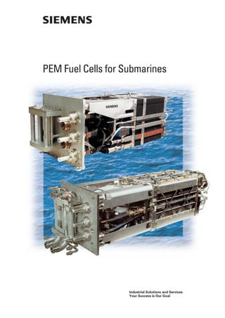
- 3. Fuel cells allow the direct generation of electric power from hydrogen and oxygen with a consid- erably better efficiency and no pollutant emission compared to conventional combustion engines. Their operation is noiseless. In addition to these basic advantages, the fuel cell with a solid, ion conducting, polymeric mem- brane (Polymer Electrolyte Membrane – PEM) has further positive properties: • Quick switch-on, switch-off behavior • Low voltage degradation and long service life • Favorable load and temperature cycle behavior • Overload possibility • Low operating temperature (80°C) • Absence of a liquid corrosive electrolyte. All these characteristics make the PEM fuel cell (PEM FC) an ideal power unit. Aboard submarines they show their outstanding advantages against conventional AIP systems (Air Independent Propulsion) using oxygen and hydrogen, carried on board. The new submarines of class U 212 A are equipped with PEM FC modules with an electri- cal output of 30 to 40 kW each, which have been developed since 1985 on behalf of the German Ministry of Defense. The new type U 214 class submarines will be fitted with 120 kW fuel cell modules which have been developed by Siemens in a next step. The basic suitability of fuel cell technology onboard submarines has been demonstrated by installing a 100 kW FC power plant with alkaline fuel cells on the submarine U1 of the Federal German Navy in 1988. During the tests the performance of additional equipment such as H2 and O2 components has been proven. Further possible applications of PEM FCs for power generation are listed below (see also Fig. 1, left side): Using hydrogen and oxygen • Operation in spacecrafts • Component in a long-term energy storage system (consisting of solar cells, an electrol- yser system and a hydrogen/oxygen storage system) Using hydrogen and air • Zero emission operation of electrically driven vehicles Using reformer gas and air • Power supply far distant from a public power supply system • Safe, low emission power supply on cargo vessels especially in harbor • Utilization of boil-off gases aboard gas tankers • Power supply e.g. for drives on rail vehicles Concentrating on manufacture and development of fuel cells for AIP applications, Siemens demonstrated its technological competence in projects for air-breathing PEM fuel cells, e.g. – Fork lift truck – Micro co-generation – Propulsion systems for busses. The Siemens R&D activities in the fields of Direct Methanol Fuel Cells (DMFC) and Solid Oxide Fuel Cells (SOFC) are not presented in this brochure. Introduction OxygenHydrogen Energy Water 3 Cover photo: 30–40 kW module (top) and 120 kW module (below)
- 4. Both the basic function and the design of the PEM FC are very simple (Fig. 2): the electrochemical element at which the chemical energy is converted into electrical energy is the membrane electrode unit. It consists of the poly- mer electrolyte, the gas diffusion elec- trodes with a platinum catalyst and carbon sheets on each side. After the abstraction of the electrons from hydrogen – they flow from the anode via the electrical load to the cathode – the resulting protons migrate from the anode to the cathode where they combine with oxygen (and the electrons) to water. The theoretical voltage of an H2/O2 fuel cell is 1.48 V (referred to the upper heat value of hydrogen). At zero load conditions, slightly more than 1 V per cell is avail- able. The cooling units or bipolar plates in combination with carbon diffusion lay- ers distribute the reactants uniformly across the area of the cell, conduct the electrons across the stack, remove the heat from the electrodes and separate the media from each other. PEM fuel cell Fig. 3: Components of cell Fig. 5: Comparison of cells: 120 kW type (front) 30–40 kW type (back) 4 Fig. 3 shows the two core compo- nents of a cell with outside dimen- sions of 400 mm x 400 mm. As used in 30–40 kW modules. Fig. 5 compares the bipolar plate of the 30–40 kW modules to the 120 kW type. Two cells of the 120 kW type produce about twice the power of one cell of the 30–40 kW type with nearly the same active area. The in principle high development potential in regard to the membrane material is shown in Fig. 4. With improved materials the power density can nearly be doubled. The voltage of a PEM FC referred to the operating time is stable, degrada- tion rates are less than 2 µV/h for the 30–40 kW module (Fig. 6). Cooling unit Membrane electrode unit Cooling unit 400 mm
- 5. 1500 1000 500 CelloutputPz 0 W 1.1 V 0.9 0.7 0.5 CellVoltageUz 0 500 1000 1500 2000A CurrentI TKW pO2 pH2 pK Aact = ~80°C = 2.3 bar abs. = 2.0 bar abs. = 5.0 bar abs. = 1163 cm2 Dow (G 29) Naf 115 (D 14) Naf 117 (A 37) Dow Naf 115 Naf 117 60 56 54 52 50 Module voltage [V] Degradation of voltage (single cell): (55.75-55.56V)/72cells/1.500h = 1.76µV/h 1000 500 0 Module Current [I] 55.75V 55.56V Operating time [h]2000 600400 800 1500 pO2 : 2,3 bar a pH2 : 2,0 bar a Temp.: 80° C Fakt.: 1163 cm2 Zellenzahl: 72 Electrical load Polymer electrolyte Product water H2O + O2 Oxygen O2 Hydrogen H2 Waste heat 4e– H+ Anode Cathode H+ H+ H+ O2+4e–= 2H2O 20- - 20--+4H+= 4e–=2H2– 4H+ Fig. 2: Functional principle Fig. 4: Potential output increase when using various electrolytes Fig. 6: Voltage degradation referred to operating time (measurement from 30–40 kW module)
- 6. Fuel cell modules Fuel cell power plant The fuel cells need additional auxiliaries for their operation. The FC stack, valves, piping and sensors form the FC module, the corresponding module electronics controls the proper opera- tion of the FC process. The ancillaries comprise the equipment for supplying H2, O2 and N2, for reactant humidifica- tion, for product water, waste heat and residual gas removal. The FC stack and the ancillaries are installed in a contain- er which is filled with inert gas (N2) at 3.0 bar abs. to prevent a release of H2 and/or O2 in the case of leakage. The FC module can be operated at vari- ous static load currents. Currents below 650 A for 30–40 kW modules or below 560 A for 120 kW modules respectively can be applied in continu- ous operation. The output power/cur- rent characteristics for 30–40 kW modules are shown in Fig. 7. For currents above the rated current the loading time is limited due to the insufficient heat removal at such work- ing points. Even loads up to the double of the rated current can be applied for a short time. At the rated operating point, the over- all efficiency is approximately 59% referred to the lower heat value of H2 (LHV). It increases in the part load range, reaching a maximum of approxi- mately 69% at a load factor of some 20% of the rated current (approx. 100 A) (Fig. 8). The properties of the 30–40 kW and 120 kW modules are listed in the table. Suitable operating conditions for fuel cell modules are provided for subma- rine application by a fuel cell system in which fuel cell modules are connected • to the hydrogen and oxygen supply • to disposal units such as for – cooling – residual gas – reaction water • to auxiliary systems such as for – inert gas drying – nitrogen supply – evacuating system • to the propulsion/ship’s system as the purpose of the whole FC system. Operator control and visualization of the fuel cell system is effected by the integrated platform management sys- tem, or directly by the control panel of the fuel cell system. Fig. 10 gives a simplified impression of the AIP system. The fuel cell system in its entirety – the complete fuel cell power plant, especially the supply and disposal sys- tems described above for AIP opera- tion including spatial and functional integration on board – has been devel- oped by HDW (Howaldtswerke Deutsche Werft AG). The new submarine classes U 212 A and U 214 are equipped with the new fuel cell power plant by HDW with the PEM fuel cell modules by Siemens. Fig. 9 shows PEM fuel cell modules assembled in a test rack. 6 Technical data Rated power 30–40 kW 120 kW Voltage, about 50–55 V 215 V Efficiency at rated load 59% 58% Efficiency at 20% load 69% 68% Operating temperature 80°C H2 pressure 2.3 bar abs. O2 pressure 2.6 bar abs. Dimensions H = 48 cm 50 cm W = 48 cm 53 cm L = 145 cm 176 cm Weight (without module electronics) 650 kg 900 kg
- 7. Propulsion switchboard Feeding of propulsion/ship’s system H2 supply O2 supply Removal • Waste heat • Product water • Residual gas Integrated Platform Management System (IPMS) FUEL CELL MODULES Fuel cell system Control panel Module electronics Control and monitoring kW 0 ModuleoutputPM 0 A Module current IM TKW pO2 pH2 pK Aact n Membrane: Nafion 117 = ~80°C = 2.3 bar abs. = 2.0 bar abs. = 5.0 bar abs. = 1163 cm2 = 72 Cells 60 200 400 600 800 1000 10 20 30 50 1200 40 % 0 Overallefficiencyηo 0 A Module current IM TKW pO2 pH2 pK Aact n Membrane: Nafion 117 = ~80°C = 2.3 bar abs. = 2.0 bar abs. = 5.0 bar abs. = 1163 cm2 = 72 Cells 100 100 200 300 400 500 20 40 60 80 600 After the successful development the FC modules are now under manufacturing. They have proven their performance and reliability in extensive tests including long term tests. They are an integral part of an AIP system for modern sub- marines like that of Class U 212 A (30–40 kW modules) and U 214 (120 kW modules). The field for use of PEM FC will be widened when suitable reform- ers produce hydrogen from liquid fuels, e.g. methanol. Then it may be possible that fuel cells can become the sole power source of submarines of the future. Using PEM fuel cells and replac- ing oxygen with air, they are an interesting alternative for environ- mental-friendly power generation, e.g. for vehicles in cities. In general: the excellent operating performance of PEM fuel cells like high efficiency and noiseless oper- ation can lead to a promising future upon further reduction in manufacturing and operating costs. Fig. 7: Module output referred to load current (measurement from 30–40 kW module) Fig. 8: Efficiency (measurement from 30–40 kW module) Fig. 10: Integrated AIP system Outlook 7 Fig. 9: PEM fuel cell modules assembled in a test rack
- 8. Order No. E10001-A930-A35-V3-7600 Dispo No. 16600 Printed in Germany 174D6077 PA 08012. Our Program Systems Engineering and Quality Management Propulsion Systems Air-Independent Propulsion (AIP) Electrical Systems Integrated Platform Management System Auxiliary Systems Engineering Logistics Service Published by Siemens AG Industrial Solutions and Services Marine Solutions P.O. Box 10 56 09 D-20038 Hamburg Tel. +49/40/28 89-27 00 Fax +49/40/28 89-36 80 marine.solutions@hbg.siemens.de Siemens AG Industrial Solutions and Services Marine Solutions Postfach 32 40 D-91050 Erlangen Tel. (0 91 31) 7-2 71 79 Fax (0 91 31) 7-2 68 35 marine.solutions@erl9.siemens.de www.marine-solutions.de Siemens Aktiengesellschaft Subject to change without prior notice © Siemens AG 2001 All rights reserved Solutions