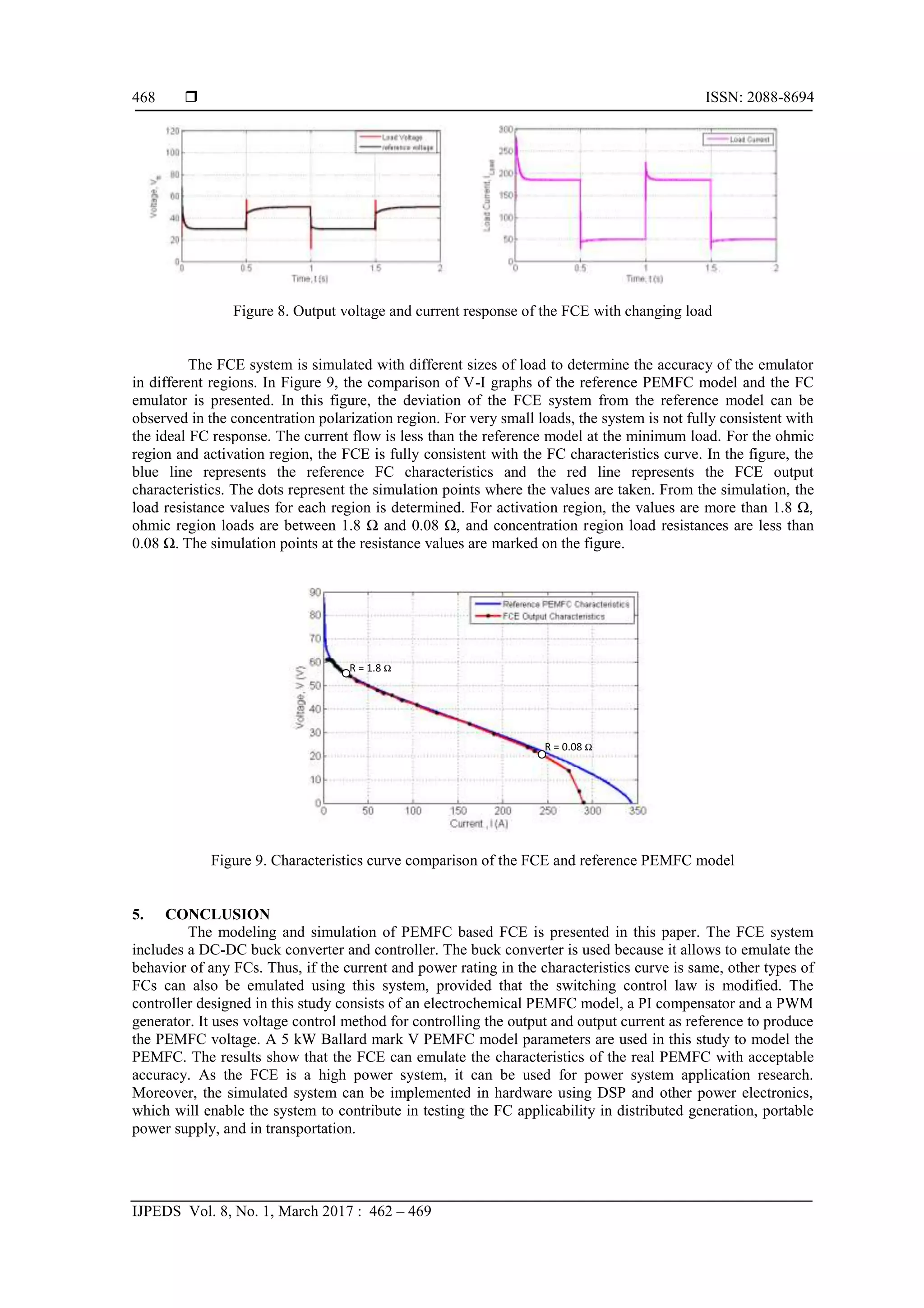
Alternative energy technologies are being popular for power generation applications nowadays. Among others, Fuel cell (FC) technology is quite popular. However, the FC unit is costly and vulnerable to any disturbances in input parameters. Thus, to perform research and experimentation, Fuel cell emulators (FCE) can be useful. FCEs can replicate actual FC behavior in different operating conditions. Thus, by using it the application area can be determined. In this study, a FCE system is modelled using MATLAB/Simulink®. The FCE system consists of a buck DC-DC converter and a proportional integral (PI) based controller incorporating an electrochemical model of proton exchange membrane fuel cell (PEMFC). The PEMFC model is used to generate reference voltage of the controller which takes the load current as a requirement. The characteristics are compared with Ballard Mark V 5kW PEMFC stack specifications obtained from the datasheet. The results show that the FCE system is a suitable replacement of real PEMFC stack and can be used for research and development purpose.
Prioritizing Power demand response for Hydrogen PEMFCElectric Vehicles using ...IJECEIAES
PEMFC powered Hybrid vehicle system is one of an interesting issue for the industry due to its high performances. The PEMFC cannot certainly ensure a sustained required energy in some scenarios. To solve this problem related to PEMFC transient response, a Hybrid Electrical Storage System (HES) is a potential candidate for a solution. The proposed Hybrid Storage system is comprised of the battery (BT) and a Super-Capacitor (SC) components. These components are included to control the hydrogen variations and the fast peak powers scenarios respectively. The SC is used to control PEMFC and the BT slow dynamics at the same times. An accurate Multi-Ways Energy Management System (MW-EMS) is proposed which aims to cooperate with the system components through SC/BT state of charge and a flux calculation. The simulation results are discussed and assessed using MATLAB/ Simulink.
Maximum Power Point Tracking Charge Controller for Standalone PV SystemTELKOMNIKA JOURNAL
The depletion of conventional energy sources and global warming has raised worldwide
awareness on the usage of renewable energy sources particularly solar photovoltaic (PV). Renewable
energy sources are non-polluting sources which can meet energy demands without causing any
environmental issues. For standalone PV systems, a low conversion efficiency of the solar panel and high
installation cost due to storage elements are the two primary constraints that limit the wide spread use of
this system. As the size of the system increases, the demand for a highly efficient tracking and charging
system is very crucial. Direct charging of battery with PV module will results in loss of capacity or
premature battery degradation. Furthermore, most of the available energy generated by the PV module or
array will be wasted if proper tracking technique is not employed. As a result, more PV panels need to be
installed to provide the same output power capacity. This paper presents selection, design and simulation
of maximum power point tracker (MPPT) and battery charge controller for standalone Photovoltaic (PV)
system. Contributions are made in several aspects of the whole system, including selection of suitable
converter, converter design, system simulation, and MPPT algorithm. The proposed system utilizes direct
duty cycle technique thus simplifying its control structure. MPPT algorithm based on scanning approach
has been applied by sweeping the duty cycle throughout the I -V curve to ensure continuous tracking of the
maximum power irrespective of any environmental circumstances. For energy storage, lead acid battery is
employed in this work. MATLAB/Simulink® was utilized for simulation studies. Results show that the
propose strategy can track the MPPs and charge the battery effectively.
International Journal of Engineering Research and DevelopmentIJERD Editor
• Electrical, Electronics and Computer Engineering,
• Information Engineering and Technology,
• Mechanical, Industrial and Manufacturing Engineering,
• Automation and Mechatronics Engineering,
• Material and Chemical Engineering,
• Civil and Architecture Engineering,
• Biotechnology and Bio Engineering,
• Environmental Engineering,
• Petroleum and Mining Engineering,
• Marine and Agriculture engineering,
• Aerospace Engineering.
In this paper, a complete description of dynamic modeling of proton exchange membrane fuel cell (PEMFC) and solid oxide fuel cell (SOFC) is given. For modeling of fuel cell for software based study, calculation of all voltage drops during chemical reaction of fuel is required. Additionally a flow chart of fuel cell output voltage calculation is also explained which includes fuel cell voltage, double layer charging effect, thermodynamic response and terminal voltage of fuel cell. By using ac to dc converter, the fuel cell power can be connected to load or grid. Based on this study, a mathematical model of fuel cell is developed in simulink software MATLAB to obtain output characteristic of fuel cell. Pratik Mochi | Mihir Bhatt"Dynamic Modeling of PEMFC and SOFC" Published in International Journal of Trend in Scientific Research and Development (ijtsrd), ISSN: 2456-6470, Volume-2 | Issue-3 , April 2018, URL: http://www.ijtsrd.com/papers/ijtsrd11087.pdf http://www.ijtsrd.com/engineering/electrical-engineering/11087/dynamic-modeling-of-pemfc-and-sofc/pratik-mochi
The electrical and environmental parameters of polymer solar cells (PSC) provide important information on their performance. In the present article we study the influence of temperature on the voltage-current (I-V) characteristic at different temperatures from 10 °C to 90 °C, and important parameters like bandgap energy Eg, and the energy conversion efficiency η. The one-diode electrical model, normally used for semiconductor cells, has been tested and validated for the polemeral junction. The PSC used in our study are formed by the poly(3-hexylthiophene) (P3HT) and [6,6]-phenyl C61-butyric acid methyl ester (PCBM). Our technique is based on the combination of two steps; the first use the Least Mean Squares (LMS) method while the second use the Newton-Raphson algorithm. The found results are compared to other recently published works, they show that the developed approach is very accurate. This precision is proved by the minimal values of statistical errors (RMSE) and the good agreement between both the experimental data and the I-V simulated curves. The obtained results show a clear and a monotonic dependence of the cell efficiency on the studied parameters.
Harvesting in electric vehicles: Combining multiple power tracking and fuel-c...IJECEIAES
Exploitation of green energy sources is essential to diminish the deterioration of our environment. The energy harvesting, represents an alternative to achieve greater range in electric and hybrid vehicles. An energy management strategy (EMS) must be optimized to obtain the best benefits in such vehicles, which is not a trivial task. If harvesting or energy recovery devices are added, the EMS becomes a dual-purpose algorithm: minimizing fuel consumption and maximizing energy harvest through maximum power point tracking (MPPT) controllers. Known studies consider separate EMS, one for traction and another for regenerative braking, without considering harvest devices such as solar panels, regenerative suspension, thermal generators, among others. Furthermore, the electronic power converters used, are not designed to handle such unequal power levels. In this article, an electronic platform to include multiple energy harvesting devices in a fuel-cell hybrid electric vehicle, was presented together with a multiple MPPT-EMS. The EMS is easily implementable, and considers quasi-constant cell energy extraction and filtering of current transients to the battery bank ensuring the longevity of the devices. A new mathematical model of the platform, a closed loop stability analysis, and numerical and Hardware-in-the-Loop (HIL) validations were presented. Some experimental validation results were also provided.
Performance Analysis of DC Micro Grid with PV-Fuel Cell Hybrid GenerationIJMREMJournal
Conventional energy resources are being replaced by Renewable energy sources mainly due to increasing
environmental concerns. Photovoltaic (PV) and Fuel cell (FC) are suitable to be used in modern DC microgrids
due to their DC output. In this research work, a DC microgrid structure is proposed for small residential areas
using hybrid PV and FC generation. Power Electronic converters are used to regulate generated voltage of the
two sources for integration to a common DC bus. Proposed system is simulated using MATLAB SIMULINK to
observe its performance. Simulation results show that output voltage is properly maintained at different DC
Today, the transportation sector has undergone a change from conventional vehicle to hybrid electric vehicle especially land-based with the aim to reduce fuel consumption and emissions. However, water transportation is also one of the contributors of excessive use of fuel and emissions. Therefore, water transport needs changes as it has been done on land transport, especially cars. In this paper, plug in hybrid electric recreational boat (PHERB) is introduced. PHERB is a special model because in PHERB powertrain configuration, it only needed one EM compared to existing configuration with energy management strategy (EMS). In this work, the optimal EMS for PHERB are presented via genetic algorithm (GA). To estimate the fuel economy and emissions, the model of PHERB is employed numerically in the MATLAB/SIMULINK environment with a special EMS using Kuala Terengganu (KT) river driving cycle. Simulation result of PHERB optimization using GA improve to 15% for KT river driving cycles without violating the PHERB performance.
Due to the increasing concern for environment protection and the uncertainty about oil reserves, nowadays electricity is playing a key role as an alternative energy source in the automotive sector. In this paper, non isolated bidirectional converter is used for electric vehicle application during regenerative braking process. During motoring operation, the converter supplies energy to motor through battery. In regenerative braking action, the converter supplies the available back emf to charge the battery. The recycled energy is effectively stored in the battery. The simulation is carried out in MATLAB/Simulink. The worthiness of simulation is illustrated experimentally by developing a prototype. The simulation and experimental results are presented in this paper.
There is need for an energy storage device capable of transferring high power in transient situations
aboard naval vessels. Currently, batteries are used to accomplish this task, but previous research has
shown that when utilized at high power rates, these devices deteriorate over time causing a loss in lifespan.
It has been shown that a hybrid energy storage configuration is capable of meeting such a demand while
reducing the strain placed on individual components. While designing a custom converter capable of
controlling the power to and from a battery would be ideal for this application, it can be costly to develop
when compared to purchasing commercially available products. Commercially available products offer
limited controllability in exchange for their proven performance and lower cost point - often times only
allowing a system level control input without any way to interface with low level controls that are
frequently used in controller design. This paper proposes the use of fuzzy logic control in order to provide
a system level control to the converters responsible for limiting power to and from the battery. A system
will be described mathematically, modeled in MATLAB/Simulink, and a fuzzy logic controller will be
compared with a typical controller.
Partial Shading Detection and MPPT Controller for Total Cross Tied Photovolta...IDES Editor
This paper present Maximum Power Point Tracking
(MPPT) controller for solving partial shading problems in
photovoltaic (PV) systems. It is well-known that partial shading
is often encountered in PV system issue with many
consequences. In this research, PV array is connected using
TCT (total cross-tied) configuration including sensors to
measure voltage and currents. The sensors provide inputs for
MPPT controller in order to achieve optimum output power.
The Adaptive Neuro Fuzzy Inference System (ANFIS) is
utilized in this paper as the controller methods. Then, the
output of MPPT controller is the optimum power duty cycle
(α) to drive the performance DC-DC converter. The simulation
shows that the proposed MPPT controller can provide PV
voltage (VMPP) nearly to the maximum power point voltage.
The accuracy of our proposed method is measured by
performance index defined as Mean Absolute Percentage Error
(MAPE). In addition, the main purpose of this work is to
present a new method for detecting partial condition of
photovoltaic TCT configuration using only 3 sensors. Thus,
this method can streamline the time and reduce operating
costs.
Sizing Optimization of Stand-Alone Wind Power System Using Hybrid Energy Stor...ijsrd.com
In this study, the hydrogen production potential and costs by using wind/electrolysis system were considered. In order to evaluate costs and quantities of produced hydrogen, number of wind-turbines and hub heights are considered as the variable Levelized cost of electricity method was used in order to determine the cost analysis of wind energy and hydrogen production. The results of calculations brought out that the electricity costs of the wind turbines and hydrogen production costs of the electrolyzers are decreased with the increase of turbine hub height. The maximum hydrogen production quantity was obtained 1420KWh/year.
STUDY OF 1.26 KW – 24 VDC PROTON EXCHANGE MEMBRANE FUEL CELL’S (PEMFC’S) PARA...ecij
The eternally intensifying exigency for electrical energy and the mount in the electricity expenditures due to the recent transience of the oil charges over and above to the desensitizing of the air standard resulting from the ejections of the obtaining energy transmutation devices have amplified exploration into substitute renewable proveniences of electrical energy. In today, there are six antithetical types of fuel cell
technologies attainable – molten carbonate fuel cells; phosphoric acid fuel cells; solid oxide fuel cells; alkaline fuel cells; polymer electrolyte membrane fuel cells and direct methanol-air fuel cells. Polymer electrolyte membrane (PEM) fuel cells – also known proton exchange membrane fuel cells, which are one of the uncomplicated types of fuel cell. PEMFC’s output power is unpredicted on nonlinearly on its output voltage and current. The output current of a proton exchange membrane fuel cell stack relies on the load located on that particular stack. This paper presents a 1.26 kW -24 Vdc PEMFC system and DC – DC boost converter topology used in 1.26 kW PEM fuel cell to fortify that the zenith obtainable output power
from a PEM membrane fuel cell is distributed to a load during a power outage bridging the start-up time and to optimize the health of the fuel cell membrane stack. A 1.26 kW – 24 Vdc PEMFC system is considered in this study as well as investigate how the output behaves.
STUDY OF 1.26 KW – 24 VDC PROTON EXCHANGE MEMBRANE FUEL CELL’S (PEMFC’S) PARA...ecij
The eternally intensifying exigency for electrical energy and the mount in the electricity expenditures due
to the recent transience of the oil charges over and above to the desensitizing of the air standard resulting
from the ejections of the obtaining energy transmutation devices have amplified exploration into substitute
renewable proveniences of electrical energy. In today, there are six antithetical types of fuel cell
technologies attainable – molten carbonate fuel cells; phosphoric acid fuel cells; solid oxide fuel cells;
alkaline fuel cells; polymer electrolyte membrane fuel cells and direct methanol-air fuel cells. Polymer
electrolyte membrane (PEM) fuel cells – also known proton exchange membrane fuel cells, which are one
of the uncomplicated types of fuel cell. PEMFC’s output power is unpredicted on nonlinearly on its output
voltage and current. The output current of a proton exchange membrane fuel cell stack relies on the load
located on that particular stack. This paper presents a 1.26 kW -24 Vdc PEMFC system and DC – DC
boost converter topology used in 1.26 kW PEM fuel cell to fortify that the zenith obtainable output power
from a PEM membrane fuel cell is distributed to a load during a power outage bridging the start-up time
and to optimize the health of the fuel cell membrane stack. A 1.26 kW – 24 Vdc PEMFC system is
considered in this study as well as investigate how the output behaves.
Designing Controller for Joined Dynamic Nonlinear PEMFC and Buck Converter Sy...IJPEDS-IAES
Designing controller for a class of dynamical nonlinear model for Polymer Electrolyte Membrane Fuel Cell (PEMFC) is discussed in this paper inwhich the PEMFC system is used for powering a Notebook PC (Processing Computer). The power requirement of a Notebook PC varies significantly under different operational conditions. The proposed feedback controller is applied for the buck dc/dc converter to stabilize the load voltage at a desirable level under various operational conditions. The simulation results show the promising performance of the proposed controller at the different operating conditions.
This paper presents a combined operation of the Unified Power Quality Conditioner (UPQC) with Fuel cell system (FC). The proposed system consists of a series inverter, a shunt inverter and a Fuel cell that is connected with the DC link of UPQC through a back boost converter, where it is a SEPIC converter. The mean purpose for using the SEPIC converter is ensuring a constant DC link voltage value and to make the FC system intervening only in the case when the DC link energy is insufficient. Excepting this case, the FC system will be in the standby state. To validate the proposed topology, several sags of source voltage have been applied, at the point of common coupling (PCC).The simulation results from MATLAB/SIMULINK are discussed to verify the proposed topology.
Experimental study on transient response of fuel celljournalBEEI
This research work discusses a control strategy to enhance the transient response of the fuel cell and boost the real and reactive power flow from grid connected to fuel cell. The current output of the fuel cell depends on the availability of hydrogen in the fuel cell stack, a battery bank is implemented to supply the transient current and to prevent it from hydrogen saturation. The battery should only supply when there is a transient. During steady state the total power is produced by the fuel cell by regulating its hydrogen input. A prototype of the system will be created to study a control scheme which regulates the current from an input source and a battery which is connected to a dc motor. The control philosophy is based on d-q transformation and subsequently generating a reference signal that is tracked by an IGBT based inverter. The speed of the motor is controlled using pulse with modulation. The dynamic modeling of the standalone fuel cell that is connected to a dc motor is carried out using MATLAB/SIMULINK platform. The simulation results show that the control scheme works well, although the dynamic response of the system can be improved. The testing carried on the prototype proves that the concept works well, but a hydrogen control scheme should be developed to improve the efficiency of the control scheme.
International Journal of Engineering Research and DevelopmentIJERD Editor
Electrical, Electronics and Computer Engineering,
Information Engineering and Technology,
Mechanical, Industrial and Manufacturing Engineering,
Automation and Mechatronics Engineering,
Material and Chemical Engineering,
Civil and Architecture Engineering,
Biotechnology and Bio Engineering,
Environmental Engineering,
Petroleum and Mining Engineering,
Marine and Agriculture engineering,
Aerospace Engineering.
Performance comparison of PEMFC hydrogen reformer with different controllersTELKOMNIKA JOURNAL
The renewable energy technology has become very popular due to major constraint in
the existing electrical system such as high electricity demand, increased in fuel prices and concern of
environmental pollution. The aims of this project are to develop a complete Proton Exchange Membrane
Fuel Cell (PEMFC) model with hydrogen reformer by using MATLAB/Simulink with three different
controllers and comparison between the three controllers will be discussed. This project presents
the development of methods to solve the problem of PEMFC output voltage by using different controllers
which are Proportional Integral (PI), Proportional Integral Derivatives (PID) and Proportional Integral Fuzzy
(PI-Fuzzy) controllers. The Ziegler Nicholas tuning method is used to tune PI and PID gains in a Simulink
model. It helps the system to achieve a balance between performance and robustness for both controllers.
The Mamdani type was used to develop the fuzzy controller in Simulink model. The transient performances
that will be discussed are rise time, settling time, maximum overshoot, and percentage of overshoot.
The results show that the proposed PI-Fuzzy is better than the conventionally used PI and PID controllers.
Improved backtracking search optimization algorithm for PV/Wind/FC systemTELKOMNIKA JOURNAL
This paper uses a novel optimization method based on the improved backtracking search optimization algorithm (IBSA). The study is conducted for a hybrid stand-alone system composed of photovoltaic panel (PV), wind turbine generator and fuel cell electrolyzer (FC). To demonstrate the effectiveness of the IBSA, four benchmark functions are used. The result shows the better exploration and exploitation of the improved backtracking search optimization algorithm in terms of convergence and speed for system comprinsing PV panel wind, turbine generator and fuel cell. The proposed algorithm is used to optimize the annual total cost (ATC) of the energy produced and feed up the load demand. The economic evaluation of the Hybrid PV/Wind/FC system is done throughout hourly demand and daily wind speed and insulation. The simulation results justify the robustness of the IBSA.
International Journal of Engineering Research and Applications (IJERA) is an open access online peer reviewed international journal that publishes research and review articles in the fields of Computer Science, Neural Networks, Electrical Engineering, Software Engineering, Information Technology, Mechanical Engineering, Chemical Engineering, Plastic Engineering, Food Technology, Textile Engineering, Nano Technology & science, Power Electronics, Electronics & Communication Engineering, Computational mathematics, Image processing, Civil Engineering, Structural Engineering, Environmental Engineering, VLSI Testing & Low Power VLSI Design etc.
Fuzzy logic-based energy management strategy on dual-source hybridization fo...IJECEIAES
This paper presents a fuzzy logic controller (FLC) based energy management strategy (EMS), combined with power filtering for a pure electric vehicle. The electrical power supply is provided by a hybrid energy storage system (HESS), including Li-Ion battery and supercapacitors (SCs), adopting a fully active parallel topology. The vehicle model was organized and constructed using the energetic macroscopic representation (EMR). The main objective of this work is to ensure an efficient power distribution in the proposed dual source, in order to reduce the battery degradation. To evaluate the impact of the developed design and the efficiency of the developed EMS, the proposed FLC strategy is compared to a classical EMS using SCs-filtering strategy and architecture based on battery storage model. To validate the proposed topology, simulation results are provided for the new European driving cycle (NEDC) using MATLAB/Simulink environment.
The International Journal of Engineering and Science (The IJES)theijes
The International Journal of Engineering & Science is aimed at providing a platform for researchers, engineers, scientists, or educators to publish their original research results, to exchange new ideas, to disseminate information in innovative designs, engineering experiences and technological skills. It is also the Journal's objective to promote engineering and technology education. All papers submitted to the Journal will be blind peer-reviewed. Only original articles will be published.
The papers for publication in The International Journal of Engineering& Science are selected through rigorous peer reviews to ensure originality, timeliness, relevance, and readability
Similar to Proton Exchange Membrane Fuel Cell Emulator Using PI Controlled Buck Converter (20)
The aim of this research is the speed tracking of the permanent magnet synchronous motor (PMSM) using an intelligent Neural-Network based adapative backstepping control. First, the model of PMSM in the Park synchronous frame is derived. Then, the PMSM speed regulation is investigated using the classical method utilizing the field oriented control theory. Thereafter, a robust nonlinear controller employing an adaptive backstepping strategy is investigated in order to achieve a good performance tracking objective under motor parameters changing and external load torque application. In the final step, a neural network estimator is integrated with the adaptive controller to estimate the motor parameters values and the load disturbance value for enhancing the effectiveness of the adaptive backstepping controller. The robsutness of the presented control algorithm is demonstrated using simulation tests. The obtained results clearly demonstrate that the presented NN-adaptive control algorithm can provide good trackingperformances for the speed trackingin the presence of motor parameter variation and load application.
This paper presents a fast and accurate fault detection, classification and direction discrimination algorithm of transmission lines using one-dimensional convolutional neural networks (1D-CNNs) that have ingrained adaptive model to avoid the feature extraction difficulties and fault classification into one learning algorithm. A proposed algorithm is directly usable with raw data and this deletes the need of a discrete feature extraction method resulting in more effective protective system. The proposed approach based on the three-phase voltages and currents signals of one end at the relay location in the transmission line system are taken as input to the proposed 1D-CNN algorithm. A 132kV power transmission line is simulated by Matlab simulink to prepare the training and testing data for the proposed 1D- CNN algorithm. The testing accuracy of the proposed algorithm is compared with other two conventional methods which are neural network and fuzzy neural network. The results of test explain that the new proposed detection system is efficient and fast for classifying and direction discrimination of fault in transmission line with high accuracy as compared with other conventional methods under various conditions of faults.
Among the most widespread renewable energy sources is solar energy; Solar panels offer a green, clean, and environmentally friendly source of energy. In the presence of several advantages of the use of photovoltaic systems, the random operation of the photovoltaic generator presents a great challenge, in the presence of a critical load. Among the most used solutions to overcome this problem is the combination of solar panels with generators or with the public grid or both. In this paper, an energy management strategy is proposed with a safety aspect by using artificial neural networks (ANNs), in order to ensure a continuous supply of electricity to consumers with a maximum solicitation of renewable energy.
In this paper, the artificial neural network (ANN) has been utilized for rotating machinery faults detection and classification. First, experiments were performed to measure the lateral vibration signals of laboratory test rigs for rotor-disk-blade when the blades are defective. A rotor-disk-blade system with 6 regular blades and 5 blades with various defects was constructed. Second, the ANN was applied to classify the different x- and y-axis lateral vibrations due to different blade faults. The results based on training and testing with different data samples of the fault types indicate that the ANN is robust and can effectively identify and distinguish different blade faults caused by lateral vibrations in a rotor. As compared to the literature, the present paper presents a novel work of identifying and classifying various rotating blade faults commonly encountered in rotating machines using ANN. Experimental data of lateral vibrations of the rotor-disk-blade system in both x- and y-directions are used for the training and testing of the network.
This paper focuses on the artificial bee colony (ABC) algorithm, which is a nonlinear optimization problem. is proposed to find the optimal power flow (OPF). To solve this problem, we will apply the ABC algorithm to a power system incorporating wind power. The proposed approach is applied on a standard IEEE-30 system with wind farms located on different buses and with different penetration levels to show the impact of wind farms on the system in order to obtain the optimal settings of control variables of the OPF problem. Based on technical results obtained, the ABC algorithm is shown to achieve a lower cost and losses than the other methods applied, while incorporating wind power into the system, high performance would be gained.
The significance of the solar energy is to intensify the effectiveness of the Solar Panel with the use of a primordial solar tracking system. Here we propounded a solar positioning system with the use of the global positioning system (GPS) , artificial neural network (ANN) and image processing (IP) . The azimuth angle of the sun is evaluated using GPS which provide latitude, date, longitude and time. The image processing used to find sun image through which centroid of sun is calculated and finally by comparing the centroid of sun with GPS quadrate to achieve optimum tracking point. Weather conditions and situation observed through AI decision making with the help of IP algorithms. The presented advance adaptation is analyzed and established via experimental effects which might be made available on the memory of the cloud carrier for systematization. The proposed system improve power gain by 59.21% and 10.32% compare to stable system (SS) and two-axis solar following system (TASF) respectively. The reduced tracking error of IoT based Two-axis solar following system (IoT-TASF) reduces their azimuth angle error by 0.20 degree.
Kosovo has limited renewable energy resources and its power generation sector is based on fossil fuels. Such a situation emphasizes the importance of active research and efficient use of renewable energy potential. According to the analysis of meteorological data for Kosovo, it can be concluded that among the most attractive potential wind power sites are the locations known as Kitka (42° 29' 41" N and 21° 36' 45" E) and Koznica (42° 39′ 32″ N, 21° 22′30″E). The two terrains in which the analysis was carried out are mountain areas, with altitudes of 1142 m (Kitka) and 1230 m (Koznica). the same measuring height, about 84 m above the ground, is obtained for these average wind speeds: Kitka 6,667 m/s and Koznica 6,16 m/s. Since the difference in wind speed is quite large versus a difference in altitude that is not being very large, analyses are made regarding the terrain characteristics including the terrain relief features. In this paper it will be studied how much the roughness of the terrain influences the output energy. Also, that the assumption to be taken the same as to how much they will affect the annual energy produced.
Large-scale grid-tied photovoltaic (PV) station are increasing rapidly. However, this large penetration of PV system creates frequency fluctuation in the grid due to the intermittency of solar irradiance. Therefore, in this paper, a robust droop control mechanism of the battery energy storage system (BESS) is developed in order to damp the frequency fluctuation of the multi-machine grid system due to variable active power injected from the PV panel. The proposed droop control strategy incorporates frequency error signal and dead-band for effective minimization of frequency fluctuation. The BESS system is used to consume/inject an effective amount of active power based upon the frequency oscillation of the grid system. The simulation analysis is carried out using PSCAD/EMTDC software to prove the effectiveness of the proposed droop control-based BESS system. The simulation result implies that the proposed scheme can efficiently curtail the frequency oscillation.
This study investigates experimentally the performance of two-dimensional solar tracking systems with reflector using commercial silicon based photovoltaic module, with open and closed loop control systems. Different reflector materials were also investigated. The experiments were performed at the Hashemite University campus in Zarqa at a latitude of 32⁰, in February and March. Photovoltaic output power and performance were analyzed. It was found that the modified photovoltaic module with mirror reflector generated the highest value of power, while the temperature reached a maximum value of 53 ̊ C. The modified module suggested in this study produced 5% more PV power than the two-dimensional solar tracking systems without reflector and produced 12.5% more PV power than the fixed PV module with 26⁰ tilt angle.
This paper focuses on the modeling and control of a wind energy conversion chain using a permanent magnet synchronous machine. This system behaves a turbine, a generator, DC/DC and DC/AC power converters. These are connected on both sides to the DC bus, where the inverter is followed by a filter which is connected to the grid. In this paper, we have been used two types of controllers. For the stator side converter, we consider the Takagi-Sugeno approach where the parameters of controller have been computed by the theory of linear matrix inequalities. The stability synthesis has been checked using the Lyapunov theory. According to the grid side converter, the proportional integral controller is exploited to keep a constant voltage on the DC bus and control both types of powers. The simulation results demonstrate the robustness of the approach used.
The development of modeling wind speed plays a very important in helping to obtain the actual wind speed data for the benefit of the power plant planning in the future. The wind speed in this paper is obtained from a PCE-FWS 20 type measuring instrument with a duration of 30 minutes which is accumulated into monthly data for one year (2019). Despite the many wind speed modeling that has been done by researchers. Modeling wind speeds proposed in this study were obtained from the modified Rayleigh distribution. In this study, the Rayleigh scale factor (Cr) and modified Rayleigh scale factor (Cm) were calculated. The observed wind speed is compared with the predicted wind characteristics. The data fit test used correlation coefficient (R2), root means square error (RMSE), and mean absolute percentage error (MAPE). The results of the proposed modified Rayleigh model provide very good results for users.
This paper deals with an advanced design for a pump powered by solar energyto supply agricultural lands with water and also the maximum power point is used to extract the maximum value of the energy available inside the solar panels and comparing between techniques MPPT such as Incremental conductance, perturb & observe, fractional short current circuit, and fractional open voltage circuit to find the best technique among these. The solar system is designed with main parts: photovoltaic (PV) panel, direct current/direct current (DC/DC) converter, inverter, filter, and in addition, the battery is used to save energy in the event that there is an increased demand for energy and not to provide solar radiation, as well as saving energy in the case of generation more than demand. This work was done using the matrix laboratory (MATLAB) simulink program.
The objective of this paper is to provide an overview of the current state of renewable energy resources in Bangladesh, as well as to examine various forms of renewable energies in order to gain a comprehensive understanding of how to address Bangladesh's power crisis issues in a sustainable manner. Electricity is currently the most useful kind of energy in Bangladesh. It has a substantial influence on a country's socioeconomic standing and living standards. Maintaining a stable source of energy at a cost that is affordable to everyone has been a constant battle for decades. Bangladesh is blessed with a wealth of natural resources. Bangladesh has a huge opportunity to accelerate its economic development while increasing energy access, livelihoods, and health for millions of people in a sustainable way due to the renewable energy system.
When the irradiance distribution over the photovoltaic panels is uniform, the pursuit of the maximum power point is not reached, which has allowed several researchers to use traditional MPPT techniques to solve this problem Among these techniques a PSO algorithm is used to have the maximum global power point (GMPPT) under partial shading. On the other hand, this one is not reliable vis-à-vis the pursuit of the MPPT. Therefore, in this paper we have treated another technique based on a new modified PSO algorithm so that the power can reach its maximum point. The PSO algorithm is based on the heuristic method which guarantees not only the obtaining of MPPT but also the simplicity of control and less expensive of the system. The results are obtained using MATLAB show that the proposed modified PSO algorithm performs better than conventional PSO and is robust to different partial shading models.
A stable operation of wind turbines connected to the grid is an essential requirement to ensure the reliability and stability of the power system. To achieve such operational objective, installing static synchronous compensator static synchronous compensator (STATCOM) as a main compensation device guarantees the voltage stability enhancement of the wind farm connected to distribution network at different operating scenarios. STATCOM either supplies or absorbs reactive power in order to ensure the voltage profile within the standard-margins and to avoid turbine tripping, accordingly. This paper present new study that investigates the most suitable-location to install STATCOM in a distribution system connected wind farm to maintain the voltage-levels within the stability margins. For a large-scale squirrel cage induction generator squirrel-cage induction generator (SCIG-based) wind turbine system, the impact of STATCOM installation was tested in different places and voltage-levels in the distribution system. The proposed method effectiveness in enhancing the voltage profile and balancing the reactive power is validated, the results were repeated for different scenarios of expected contingencies. The voltage profile, power flow, and reactive power balance of the distribution system are observed using MATLAB/Simulink software.
The inverter is the principal part of the photovoltaic (PV) systems that assures the direct current/alternating current (DC/AC) conversion (PV array is connected directly to an inverter that converts the DC energy produced by the PV array into AC energy that is directly connected to the electric utility). In this paper, we present a simple method for detecting faults that occurred during the operation of the inverter. These types of faults or faults affect the efficiency and cost-effectiveness of the photovoltaic system, especially the inverter, which is the main component responsible for the conversion. Hence, we have shown first the faults obtained in the case of the short circuit. Second, the open circuit failure is studied. The results demonstrate the efficacy of the proposed method. Good monitoring and detection of faults in the inverter can increase the system's reliability and decrease the undesirable faults that appeared in the PV system. The system behavior is tested under variable parameters and conditions using MATLAB/Simulink.
The electrical distribution network is undergoing tremendous modifications with the introduction of distributed generation technologies which have led to an increase in fault current levels in the distribution network. Fault current limiters have been developed as a promising technology to limit fault current levels in power systems. Though, quite a number of fault current limiters have been developed; the most common are the superconducting fault current limiters, solid-state fault current limiters, and saturated core fault current limiters. These fault current limiters present potential fault current limiting solutions in power systems. Nevertheless, they encounter various challenges hindering their deployment and commercialization. This research aimed at designing a bridge-type nonsuperconducting fault current limiter with a novel topology for distribution network applications. The proposed bridge-type nonsuperconducting fault current limiter was designed and simulated using PSCAD/EMTDC. Simulation results showed the effectiveness of the proposed design in fault current limiting, voltage sag compensation during fault conditions, and its ability not to affect the load voltage and current during normal conditions as well as in suppressing the source powers during fault conditions. Simulation results also showed very minimal power loss by the fault current limiter during normal conditions.
This paper provides a new approach to reducing high-order harmonics in 400 Hz inverter using a three-level neutral-point clamped (NPC) converter. A voltage control loop using the harmonic compensation combined with NPC clamping diode control technology. The capacitor voltage imbalance also causes harmonics in the output voltage. For 400 Hz inverter, maintain a balanced voltage between the two input (direct current) (DC) capacitors is difficult because the pulse width modulation (PWM) modulation frequency ratio is low compared to the frequency of the output voltage. A method of determining the current flowing into the capacitor to control the voltage on the two balanced capacitors to ensure fast response reversal is also given in this paper. The combination of a high-harmonic resonator controller and a neutral-point voltage controller working together on the 400 Hz NPC inverter structure is given in this paper.
Direct current (DC) electronic load is a useful equipment for testing the electrical system. It can emulate various load at a high rating. The electronic load requires a power converter to operate and a linear regulator is a common option. Nonetheless, it is hard to control due to the temperature variation. This paper proposed a DC electronic load using the boost converter. The proposed electronic load operates in the continuous current mode and control using the integral controller. The electronic load using the boost converter is compared with the electronic load using the linear regulator. The results show that the boost converter able to operate as an electronic load with an error lower than 0.5% and response time lower than 13 ms.
This paper presents a new simplified cascade multiphase DC-DC buck power converter suitable for low voltage and large current applications. Cascade connection enables very low voltage ratio without using very small duty cycles nor transformers. Large current with very low ripple content is achieved by using the multiphase technique. The proposed converter needs smaller number of components compared to conventional cascade multiphase DC-DC buck power converters. This paper also presents useful analysis of the proposed DC-DC buck power converter with a method to optimize the phase and cascade number. Simulation and experimental results are included to verify the basic performance of the proposed DC-DC buck power converter.
More from International Journal of Power Electronics and Drive Systems (20)
Water scarcity is the lack of fresh water resources to meet the standard water demand. There are two type of water scarcity. One is physical. The other is economic water scarcity.
Immunizing Image Classifiers Against Localized Adversary Attacksgerogepatton
This paper addresses the vulnerability of deep learning models, particularly convolutional neural networks
(CNN)s, to adversarial attacks and presents a proactive training technique designed to counter them. We
introduce a novel volumization algorithm, which transforms 2D images into 3D volumetric representations.
When combined with 3D convolution and deep curriculum learning optimization (CLO), itsignificantly improves
the immunity of models against localized universal attacks by up to 40%. We evaluate our proposed approach
using contemporary CNN architectures and the modified Canadian Institute for Advanced Research (CIFAR-10
and CIFAR-100) and ImageNet Large Scale Visual Recognition Challenge (ILSVRC12) datasets, showcasing
accuracy improvements over previous techniques. The results indicate that the combination of the volumetric
input and curriculum learning holds significant promise for mitigating adversarial attacks without necessitating
adversary training.
Welcome to WIPAC Monthly the magazine brought to you by the LinkedIn Group Water Industry Process Automation & Control.
In this month's edition, along with this month's industry news to celebrate the 13 years since the group was created we have articles including
A case study of the used of Advanced Process Control at the Wastewater Treatment works at Lleida in Spain
A look back on an article on smart wastewater networks in order to see how the industry has measured up in the interim around the adoption of Digital Transformation in the Water Industry.
Student information management system project report ii.pdfKamal Acharya
Our project explains about the student management. This project mainly explains the various actions related to student details. This project shows some ease in adding, editing and deleting the student details. It also provides a less time consuming process for viewing, adding, editing and deleting the marks of the students.
Saudi Arabia stands as a titan in the global energy landscape, renowned for its abundant oil and gas resources. It's the largest exporter of petroleum and holds some of the world's most significant reserves. Let's delve into the top 10 oil and gas projects shaping Saudi Arabia's energy future in 2024.
2. IJPEDS ISSN: 2088-8694
Proton Exchange Membrane Fuel Cell Emulator Using PI Controlled Buck .... (Himadry Shekhar Das)
463
resembling the PV characteristics [1],[2]. Other than buck converters, buck-boost, boost, and push-pull
converters are also used for PV emulator implementation [3]-[5]. However, the control strategy becomes
complex in case of other converters. Recent works in control strategy development includes using fuzzy-PI
controller to determine the operating point [5] and microcontroller based implementation [6]. Wind turbine
emulator (WTE) consists of two mechanically connected drives: one works as a motor and another as a
generator. The motor emulates the wind torque and the generator produces electricity based on the torque.
Majority of Previously proposed WTEs use simulation and digital implementation using
MATLAB/Simulink®
with dSPACE [7], MathWorks xPC target [8] or LabVIEW with Data acquisition
board [9]. In order to emulate the inertia torque, some researchers use first order filter [7] or a moving
average filter [10] or a PLL [11] to filter the speed derivative term. A few researchers proposed
implementation of WTEs using its own specific software and hardware [11],[12]. Similar to other emulators,
fuel cell emulators (FCEs) can be constructed using either basic electronic components or digital
controllers [13]. Generally, the FCE models are programmed using MATLAB/Simulink®
and implemented
using DSP controller or dSPACE boards [14]. The emulator is constructed using DC-DC buck converter and
the controller, which includes the FC model behavior and the switch driver [15]. The main challenge of FCE
system is to emulate the fuel cell characteristics. Several emulators use electrical circuit representation of the
FC model, while others use electrochemical model to extract the characteristics of FC [15],[16]. The initial
FCEs include only the steady state behaviour [17]. Later, both the steady state and dynamic properties are
included in the emulator model [18],[19]. This can be done using either mathematical model or experimental
data of the FC.
In this paper, a FCE is designed based on a PEMFC model explained in ref [20]. The parameters are
adapted from Ballard Mark V PEMFC model datasheet. The model considers the activation, concentration,
and ohmic losses and also depicts the steady state and dynamic behaviors. The basic block diagram of the
emulator is shown in the Figure 1. The system includes a buck DC-DC converter, controller, and a DC load.
In the controller, PEMFC electrochemical model is included to produce the reference voltage and a PI
compensator is used to generate the control signal for the pulse width modulator. MATLAB/Simulink®
environment is used for the system simulation. The emulator shows fast response and it is easily scalable and
can be applied for other types of FCs. In this paper, the basic of PEMFC is elaborated in section II, the
MATLAB modelling of the FCE system is presented in section III, the simulation results and discussion is
stated in section IV, and finally, section V discusses the concluding remarks.
Buck
Converter
Load
PEMFC
Reference
Model
PI
Controller
PWM
+
-
Vref
Vo
Iref
Fuel Cell Emulator
Figure 1. Block diagram of the proposed FC emulator
2. PROTON EXCHANGE MEMBRANE FUEL CELL (PEMFC) MODEL
PEMFC produces electricity through an electrochemical reaction, in which an oxidizer reacts with a
fuel to produce electricity, where, water and heat is generated as by-product. The PEMFC construction starts
with three parts: two porous electrodes and a solid polymer electrolyte. The electrolyte works as a medium of
ion exchange between the electrodes. The main reactant of PEMFC is hydrogen from the fuel and oxygen
from the air. At anode, the hydrogen fuel is fed continuously and at cathode, air is supplied. At anode,
hydrogen is decomposed into protons and electrons, while at cathode oxygen is reduced to oxide ions and
then reacts with protons to form water. The mechanism of a PEMFC is shown in the Figure 2. The anode,
cathode, and overall chemical reactions are given in equation (1-3) [21]. Anode reaction:
(1)
3. ISSN: 2088-8694
IJPEDS Vol. 8, No. 1, March 2017 : 462 – 469
464
Cathode reaction:
⁄ (2)
Overall reaction:
( ) ( ) ( ) (3)
Load
2e
-
Oxidant in
Fuel in
H2
Positive ion
Negative ion
H2O
Depleted oxidant and
Product gases out
Electrolyte
Membrane
H2O
Depleted oxidant and
Product gases out
Anode Cathode
1/2O2
Figure 2. Principle of operation of PEMFC [22]
Each PEMFC cell produces output voltage of 1.23 V theoretically, although in practice the voltage
achieved is approximately 0.6 V ~ 0.7 V. The FC cell has several loss factors, such as activation, ohmic, and
mass transportation loss, which results in decrement in output voltage and increment in current [23]. The
characteristics curve of PEMFC cell is shown in the Figure 3 [24]. The I-V curve depicts that there are three
operating regions namely, ohmic, activation, and concentration. At the warming up stage, PEMFC operates at
the activation region as there is less current density, resulting in high terminal voltage. Again, when the
current density is very high, the opearting state reaches to concentration polarization, where the voltage drops
due to the gas transport effeciency reduction. In between the two states, there is ohmic region where the loss
is due to internal resistance and the current density as well as voltage change is linear. The ideal operating
region of the PEMFC is ohmic region, due to having minimum loss, good health, and maintaing stable
operation.
As a single FC cell output voltage and current is not sufficient for practical applications, multiple
cells are arranged in series and parallel combinations to build the FC stack. The number of cells in series
defines the output voltage and parallel combination gives the output current. The commercial fuel cell stacks
have certain voltage and current rating. Also, the fuel and oxidant flow rate and coolant specifications are
also defined. In order to apply the FC stack in power generation, the regulation of the pressure and flow rate
of all these streams are required. Moreover, the operating temperature and gas humidification are also needed
to follow up. For all these features, a complete system should include FC unit, fuel storage, fuel delivery
system, cooling system, air supply system, and a humidification system. Also, proper alarms and safety
equipemnts should be included to prevent any malfunction hazard. Electrical control systems perform the
controlling and monitoring of the different subsections.
4. IJPEDS ISSN: 2088-8694
Proton Exchange Membrane Fuel Cell Emulator Using PI Controlled Buck .... (Himadry Shekhar Das)
465
Active Polarization
Region
(reaction rate loss) Total Loss
Ohmic Polarization Region
(resistance loss)
Concentration
Polarization Region
(gas transport loss)
Figure 3. Typical fuel cell I-V curve
2.1. Dynamic model of PEMFC
The redox reaction of equation (3) produces the electrical power in a single FC cell. The voltage of a
single cell is given by the Nernst equation described in equation (4)
ln 2 2
2
H O
Cell 0
H O
E E
P P
RT
2F P
(4)
Here, (1.23V) is the standard potential of redox reaction and R, T, and F are the universal gas
constant, absolute temperature, and Farady’s constant respectively. P denotes the partial pressures of the
gases and water. The voltage obtained from equation (4) is open circuit voltage and the normal operative
voltage gets reduced from that due to the activation ( ), concentration ( ) and resistive ( ) losses of
the FC. Thus, the output voltage ( ) can be expressed as equation (5) [16].
Stack Cell Cell act conc ohm
N E
V E V V V
(5)
The voltage losses can be represented by the equation (6) to represent the output current ( ) and
voltage ( ) relation.
int
0
ln ln
stack L stack
Stack stack
L
I I I
V E AT BT I R
I I
(6)
Here, E is the open circuit voltage, and are the exchange and limiting currents, is the
internal resistance, A and B are the activation and concentration coefficients.
The dynamic model of FC includes the double layer charging effect, which is due to the two
opposite polarity charged layers formed across the membrane and the cathode. The layers behave like super
capacitors and is known as electrochemical double layer. The PEMFC characteristics can be modeled in
MATLAB/Simulink®
incorporating the temperature, partial pressure of gases, and the double layer capacitor
effects as shown in Figure 4.
5. ISSN: 2088-8694
IJPEDS Vol. 8, No. 1, March 2017 : 462 – 469
466
Figure 4. Electrochemical simulation model of PEMFC
3. SIMULATION OF PEMFC EMULATOR
The simulation diagram of PEMFC emulator is shown in the Figure 5. The emulator has three parts:
the FC model for reference voltage generation, the DC-DC converter, and the controller for emulating the
fuel cell voltage. FC model is developed based on the mathematical equations and simulated using the
Simulink blocks. The FC model demonstrates both static and dynamic characteristics of a PEMFC stack. The
parameters used in the model is given in Table 1. The FC model takes the load current as reference and
provides reference voltage of the emulator controller. The maximum power of the reference model is 5.7 kW.
The voltage-current relationship of the model is shown in the Figure 6. From the figure, it can be observed
that, the ohmic region lies approximately between 50 V and 20 V stack voltage. The maximum power is at 28
V where the current is 200 A. The power curve is similar to the characteristics of Ballard Mark V PEMFC
stack [20].
The buck converter is used to emulate the fuel cell characteristics into the load. The input voltage is
considered 100 V, which is higher than the reference FC model maximum voltage (80 V). The inductor and
capacitor values are defined using the standard buck converter formulae and the voltage and current range
considered for the modelling is the FC ohmic operating region. The switching speed of the converter is
considered 20 kHz due to convenience of hardware implementation. Also, internal resistance of the passive
elements are considered in the simulation. In order to control the buck converter, PI compensator based
controller is simulated. A voltage loop controller is designed, which compares the output voltage with the FC
reference voltage and produces control signal for the pulse width modulator (PWM). The PWM generates the
gate signal pulses of the MOSFET switch. Table 2 demonstrates the Buck converter components and
proportional and integral compensator values.
Figure 5. MATLAB/Simulink®
diagram of fuel cell emulator
6. IJPEDS ISSN: 2088-8694
Proton Exchange Membrane Fuel Cell Emulator Using PI Controlled Buck .... (Himadry Shekhar Das)
467
Table 1. Model parameters of PEMFC stack [20]
Parameters Values
Anode Partial Pressure (Pa) 2.3816
Cathode Partial Pressure (Pc) 2.3816
Thickness of FC (L) 178e-4
Concentration loss coefficient (B) 0.016
Membrane resistance (Rc) 0.0003
Parametric coefficients (E1) -0.948
Parametric coefficients (E3) 7.6e-5
Parametric coefficients (E4) -1.93e-4
Maximum current density (Jmax) 1.5
Initial current density (Jn) 0.1
FC area (A) 232
Adjustable Parameter (Y) 18
Table 2. Buck converter and controller parameters
Parameters Values
Input Voltage (Vin) 100 V
Inductor (L) 200 µH
Capacitor (B) 250 µF
Switching frequency (Rc) 20000 Hz
Proportional compensator (Kp) 0.004
Integral compensator (Ki) 5
Figure 6. Voltage and Power curve of PEMFC stack model
4. SIMULATION RESULTS AND ANALYSIS
The FCE model has been simulated with both static and dynamic load to assess the characteristics.
The results show that the emulator model replicates the behaviour of actual PEMFC stack. In Figure 7, the
voltage and current response of the FCE system with resistive load is presented. It can be seen that, the FC
reference voltage and load voltage have some ripples. Otherwise, the voltage is constant at 31V, whereas the
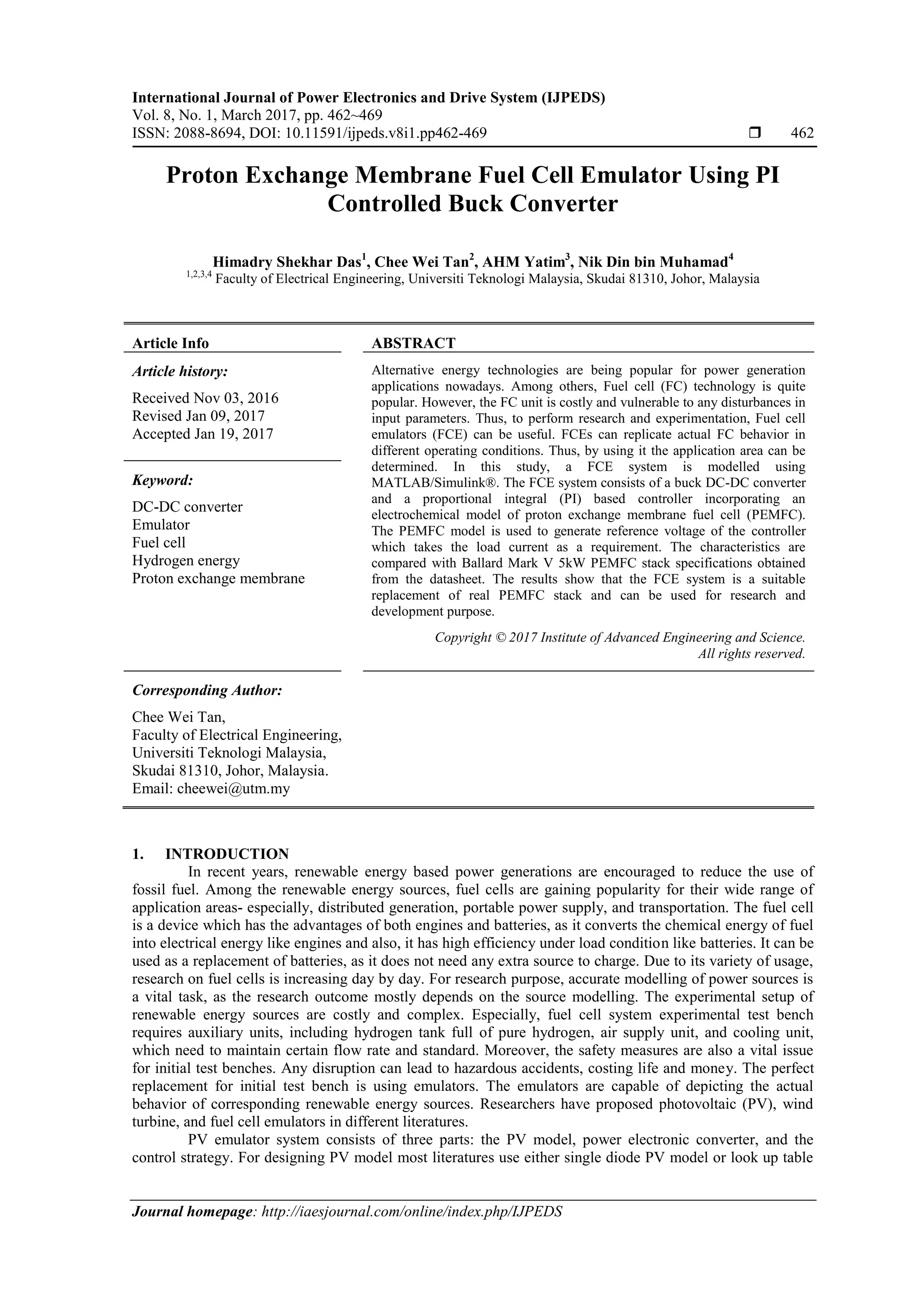
load current is .180 A. Figure 8 presents the voltage and current response of the FCE with changes in
resistive load. With the change of load resistance, the load current and voltage should change linearly.
However, there is overshoot and undershoot in both voltage and current responses. When the load resistance
increases, the load current drops and the voltage increases. However, at the moment of change, there is a
spike on load voltage as well as undershoot on load current response. The reason behind the effect is the slow
dynamic of the FC model. The model needs time to increase or decrease the current flow. Similar incident
takes place while the load resistance drops.
Figure 7. Output voltage and current response of the FCE with fixed load
7. ISSN: 2088-8694
IJPEDS Vol. 8, No. 1, March 2017 : 462 – 469
468
Figure 8. Output voltage and current response of the FCE with changing load
The FCE system is simulated with different sizes of load to determine the accuracy of the emulator
in different regions. In Figure 9, the comparison of V-I graphs of the reference PEMFC model and the FC
emulator is presented. In this figure, the deviation of the FCE system from the reference model can be
observed in the concentration polarization region. For very small loads, the system is not fully consistent with
the ideal FC response. The current flow is less than the reference model at the minimum load. For the ohmic
region and activation region, the FCE is fully consistent with the FC characteristics curve. In the figure, the
blue line represents the reference FC characteristics and the red line represents the FCE output
characteristics. The dots represent the simulation points where the values are taken. From the simulation, the
load resistance values for each region is determined. For activation region, the values are more than 1.8 Ω,
ohmic region loads are between 1.8 Ω and 0.08 Ω, and concentration region load resistances are less than
0.08 Ω. The simulation points at the resistance values are marked on the figure.
R = 0.08
R = 1.8
Figure 9. Characteristics curve comparison of the FCE and reference PEMFC model
5. CONCLUSION
The modeling and simulation of PEMFC based FCE is presented in this paper. The FCE system
includes a DC-DC buck converter and controller. The buck converter is used because it allows to emulate the
behavior of any FCs. Thus, if the current and power rating in the characteristics curve is same, other types of
FCs can also be emulated using this system, provided that the switching control law is modified. The
controller designed in this study consists of an electrochemical PEMFC model, a PI compensator and a PWM
generator. It uses voltage control method for controlling the output and output current as reference to produce
the PEMFC voltage. A 5 kW Ballard mark V PEMFC model parameters are used in this study to model the
PEMFC. The results show that the FCE can emulate the characteristics of the real PEMFC with acceptable
accuracy. As the FCE is a high power system, it can be used for power system application research.
Moreover, the simulated system can be implemented in hardware using DSP and other power electronics,
which will enable the system to contribute in testing the FC applicability in distributed generation, portable
power supply, and in transportation.
8. IJPEDS ISSN: 2088-8694
Proton Exchange Membrane Fuel Cell Emulator Using PI Controlled Buck .... (Himadry Shekhar Das)
469
ACKNOWLEDGEMENTS
The authors would like to pay gratitude to Universiti Teknologi Malaysia (UTM) for supporting
with lab and library facilities. In addition, the authors would like to express their appreciation to the Ministry
of Higher Education, Malaysia (MOHE). They also acknowledge funding provided by fundamental research
grant scheme (FRGS) under vote 4F596, Universiti Teknologi Malaysia (UTM). Lastly, thanks to those
colleagues who have either directly or indirectly contributed to the completion of this work.
REFERENCES
[1] D. Abbes, et al., “Real time supervision for a hybrid renewable power system emulator,” Simulation Modelling
Practice and Theory, vol. 42, pp. 53-72, 2014.
[2] R. G. Medina, et al., “A low‐cost photovoltaic emulator for static and dynamic evaluation of photovoltaic power
converters and facilities,” Progress in Photovoltaics: Research and Applications, vol. 22, pp. 227-241, 2014.
[3] D. D. Lu and Q. N. Nguyen, “A photovoltaic panel emulator using a buck-boost DC/DC converter and a low cost
micro-controller,” Solar Energy, vol. 86, pp. 1477-1484, 2012.
[4] J. Chavarria, et al., “Low cost photovoltaic array emulator design for the test of PV grid-connected inverters,” in
Systems, Signals & Devices (SSD), 2014 11th International Multi-Conference on, pp. 1-6, 2014.
[5] J. Zhang, et al., “Design and realization of a digital PV simulator with a push-pull forward circuit,” Journal of
Power Electronics, vol. 14, pp. 444-457, 2014.
[6] C. Balakishan and S. Babu, “Development of a Microcontroller Based PV Emulator With Current Controlled
DC/DC Buck Converter,” International Journal of Renewable Energy Research, vol. 4, pp. 1049-1055, 2014.
[7] H. Li, et al., “Development of a unified design, test, and research platform for wind energy systems based on
hardware-in-the-loop real-time simulation,” IEEE Transactions on Industrial Electronics, vol. 53, 2006.
[8] I. Munteanu, et al., “Hardware-in-the-loop-based simulator for a class of variable-speed wind energy conversion
systems: Design and performance assessment,” IEEE Transactions on Energy Conversion, vol. 25, 2010.
[9] J. R. Arribas, et al., “Computer-based simulation and scaled laboratory bench system for the teaching and training
of engineers on the control of doubly fed induction wind generators,” IEEE Transactions on Power Systems, vol.
26, pp. 1534-1543, 2011.
[10] M. Monfared, et al., “Static and dynamic wind turbine simulator using a converter controlled dc motor,” Renewable
Energy, vol. 33, pp. 906-913, 2008.
[11] B. Gong and D. Xu, “Real time wind turbine simulator for wind energy conversion system,” in 2008 IEEE Power
Electronics Specialists Conference, pp. 1110-1114, 2008.
[12] J. Chen, et al., “Design and analysis of dynamic wind turbine simulator for wind energy conversion system,” in
IECON 2012-38th Annual Conference on IEEE Industrial Electronics Society, pp. 971-977, 2012.
[13] S. Yuvarajan and D. Yu, “Characteristics and modelling of PEM fuel cells,” in Circuits and Systems, 2004.
ISCAS'04. Proceedings of the 2004 International Symposium on, vol. 5, pp. V-880-V-883, 2004.
[14] A. Gebregergis and P. Pillay, “The development of solid oxide fuel cell (SOFC) emulator,” in 2007 IEEE power
electronics specialists conference, pp. 1232-1238, 2007.
[15] G. Marsala, et al., “A prototype of a fuel cell PEM emulator based on a buck converter,” Applied Energy, vol. 86,
pp. 2192-2203, 2009.
[16] A. S. Samosir, et al., “A simple PEM fuel cell emulator using electrical circuit model,” in IPEC, 2010 Conference
Proceedings, pp. 881-885, 2010.
[17] T. W. Lee, et al., “A 3 kW fuel cell generation system using the fuel cell simulator,” in Industrial Electronics, 2004
IEEE International Symposium on, pp. 833-837, 2004.
[18] M. Ordonez, et al., “Development of a fuel cell simulator based on an experimentally derived model,” in Canadian
Conference on Electrical and Computer Engineering, 2005., pp. 1449-1452, 2005.
[19] M. Ordonez, et al., “A novel fuel cell simulator,” in 2005 IEEE 36th Power Electronics Specialists Conference, pp.
178-184, 2005.
[20] C. H. Lee and J. T. Yang, “Modeling of the Ballard-Mark-V proton exchange membrane fuel cell with power
converters for applications in autonomous underwater vehicles,” Journal of Power Sources, vol. 196, pp. 3810-
3823, 2011.
[21] M. W. Ellis, et al., “Fuel cell systems: efficient, flexible energy conversion for the 21st century,” Proceedings of the
IEEE, vol. 89, pp. 1808-1818, 2001.
[22] X. Huang, et al., “Fuel cell technology for distributed generation: an overview,” in Industrial Electronics, 2006
IEEE International Symposium on, pp. 1613-1618, 2006.
[23] A. S. Samosir, “Dynamic evolution control of bidirectional converter for interfacing ultracapacitor to fuel cell,”
PhD, Universiti Teknologi Malaysia, 2010.
[24] K. Cheng, et al., “Exploring the power conditioning system for fuel cell,” in Power Electronics Specialists
Conference, 2001. PESC. 2001 IEEE 32nd Annual, pp. 2197-2202, 2001.