IRJET- Reduction in Accident Due to Disengagement in Transmission Line
•
0 likes•14 views

https://www.irjet.net/archives/V5/i4/IRJET-V5I4398.pdf

Recommended
Recommended
More Related Content
What's hot
What's hot (20)
Similar to IRJET- Reduction in Accident Due to Disengagement in Transmission Line
Similar to IRJET- Reduction in Accident Due to Disengagement in Transmission Line (20)
More from IRJET Journal
More from IRJET Journal (20)
Recently uploaded
Recently uploaded (20)
IRJET- Reduction in Accident Due to Disengagement in Transmission Line
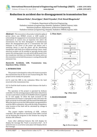
- 1. International Research Journal of Engineering and Technology (IRJET) e-ISSN: 2395-0056 Volume: 05 Issue: 04 | Apr-2018 www.irjet.net p-ISSN: 2395-0072 © 2018, IRJET | Impact Factor value: 6.171 | ISO 9001:2008 Certified Journal | Page 1789 Reduction in accident due to disengagement in transmission line Bhimani Nisha1, Desai Jigna2, Shah Priyanka3, Prof. Henal Bhagatwala4 1, 2,3 Students, Department of Electrical Engineering, Vadodara institute of engineering, Kotambi, Vadodara-390018, Gujarat, India 4Assistant professor, Department. of Electrical Engineering, Vadodara institute of engineering, Kotambi, Vadodara-390018, Gujarat, India ---------------------------------------------------------------------***--------------------------------------------------------------------- Abstract -This innovation is the product relatedtosafetyof person device uses WIMAX circuits or GSM module to acknowledge dis engagement in transmissionlineandsendthe information to control area of respective line where the transmission line has been disengaged. It simultaneously detect the disengagement pint in a transmission line and intimates to the server in the power sub station and a switching device is used the power off the distributing transformer with help of an Arduino processor hence, many electrical accident can be avoided as specially during rainy season this exiting project can only switch off the power from the transformer and does not intimates the station where as this innovation serves both the purpose i.e savingofhumanlife and power loss. Keywords: Accidents, GSM, Transmission Line, Impedance Relay, Arduino. 1. INTRODUCTION This project is developed to reduce the lossesoccurredin the transmission line & also to save human being life. This project serves mainly two purpose : (1) To send the SMS to the substation When the fault occurred in the transmission line. (2) To Find the fault location at which distance the fault is occurred. The operation of the project is operated by Ardiuno controller. For the sensing purpose of the fault, relay driven circuit is used which containsIC ULN2003 whichis supplied by 12 volt supply. So when the fault occurred in the transmission line buzzer is operated & relay will sense the fault current & circuit breaker will disconnectthefaultypart. When the fault occurred, the GSM module is programmed to send the SMS to substation. Also with the help of impedance relay location of the fault will be calculated by voltage & current ratio. This project implies interfacing of GSM ardiuno controller. The operation or functions of the GSM is carried out by fetching the programs in the Arduino by using the Arduino IDE software. Some other additional features like LCD display for display the message like “Fault is occurred at km” , So if network issue is occurred at some place LCD display shows that message. 2. Flow chart : Fig- 1 flow chart 3. BLOCK DIAGRAM Fig -2: Block diagram
- 2. International Research Journal of Engineering and Technology (IRJET) e-ISSN: 2395-0056 Volume: 05 Issue: 04 | Apr-2018 www.irjet.net p-ISSN: 2395-0072 © 2018, IRJET | Impact Factor value: 6.171 | ISO 9001:2008 Certified Journal | Page 1790 4. IMPLEMENTATION The working of the project can be understood by use of the circuit diagram for reduce the accident occur in the transmission line . Fig -3: circuit diagram We have used Ardiuno asthe main controller.Thesupply of 5V to the Arduino is given by SMPS. Relay sensing circuit ,GSM module, buzzer, impedance relay circuit are connected to the Arduino. At first,Ardiuno make the relay is on in normal condition so, current is pass through the relay & it will continuously measures the current . But when the current is increasing above certain limit then it automatically open its contact & circuit breaker trip the circuit. For that trip function buzzer is operated & it will indicate that fault is occurred. For message sending through GSM module , it is interface with ardiuno in which the program is loaded. Fig 4-: GSM & impedance relay circuit For impedance relay current transformer(each CT is rated up to 3 ampere as the rated maximum current is1.5ampere) & potential transformer are used. Here impedance is calculated by the ratio of voltage & current which are measured with the help of PT & CT respectively.Asshownin figure variable resistors are connected with PT for make sure that voltage is not exceeding above 5 volt as ardiuno required 0 to 5 volt. If voltage is increases above 5 volt it may get damage.Also in CT resistance isconnected to C.T for converting current signal in to voltage signal as ardiuno require voltage signal. As the impedance valueischangesthe distance is calculated on the basis of value of impedance. 5. RESULTS We have demonstrated this project by making the fault location circuit as well as message sending circuit.. We have used interfacing of GSM & ardiuno and impedance relay. A GSM module circuit is used for message sending operation. Impedance relay circuit is used for finding the locationofthe fault operation. It is to be noted that a buzzer will operate at every operation. By running this prototype model we got results asgetting messageslike “ fault is occurred at 60 km”, “ fault is occurred at 40 km”,“ fault is occurred at 20 km” & also on LCD display. Fig -5 : Prototype model of project 6. CONCLUSION From the project the conclusion is that,when L-Gfault occur in the transmission at any distance the relay circuit will sense that fault and relay will give the signal to the circuit breaker to isolate that faulty part, so power losses reduced. Also by the impedance relay circuit the location of the fault will be calculated by the voltage & current ratio measured which is measured by current transformer & potential transformer. Due to that the message will be send by the GSM module to the substation. Hence human life can be saved, also the accidents will be reduced. REFERENCES 1. Rahul M. Kabade , D.D Gavali ,”3 Phase Line fault Detection On Distribution lineusingGSMTechnique ” , vol-2, Issue 3, International Journal of Emerging Technology and Innovation Engineering , March 2016.
- 3. International Research Journal of Engineering and Technology (IRJET) e-ISSN: 2395-0056 Volume: 05 Issue: 04 | Apr-2018 www.irjet.net p-ISSN: 2395-0072 © 2018, IRJET | Impact Factor value: 6.171 | ISO 9001:2008 Certified Journal | Page 1791 2. Abhijit A. Dutta , M.M Rao , “Intellent control for Locating Fault In Trasmission Line” Vol 1 , Issue 2 , International journal of Instrumentation , control and Automation , 2011 3. B.A Jan , “Use Of Gps In EHV Transmission Line Fault Detection And Transmission Line Protection In Power System”, Vol 1, Issue 10 , International Journal of Emerging Science Innovation Research And Development , April 2015. 4. Komi Agbesi ,”Automatic Fault Detection And Location In Power Transmission Line Using GSM” , Vol 5, Issue 1 , International Journal of Advance research of Science and Engineering. 5. Shushil Chavhan , Abhijit Dutta , ‘Fault Detection inPower Line Using WirelessSensorNetwork’,Vol3 , Issue 3 , International Journal of Electrical Engineering , March 2015.