IRJET- Autonomous Floor Cleaning BOT
•
1 like•74 views

https://irjet.net/archives/V5/i6/IRJET-V5I6312.pdf

Recommended
Recommended
More Related Content
What's hot
What's hot (20)
Similar to IRJET- Autonomous Floor Cleaning BOT
Similar to IRJET- Autonomous Floor Cleaning BOT (20)
More from IRJET Journal
More from IRJET Journal (20)
Recently uploaded
Recently uploaded (20)
IRJET- Autonomous Floor Cleaning BOT
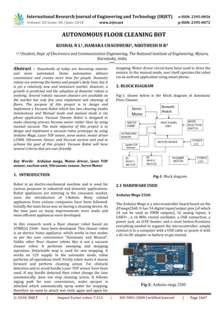
- 1. International Research Journal of Engineering and Technology (IRJET) e-ISSN: 2395-0056 Volume: 05 Issue: 06 | June-2018 www.irjet.net p-ISSN: 2395-0072 © 2018, IRJET | Impact Factor value: 7.211 | ISO 9001:2008 Certified Journal | Page 1667 AUTONOMOUS FLOOR CLEANING BOT KUSHAL N L1, HAMARA CHAUDHURI2, NIKITHESH H R3 1,2,3Student, Dept. of Electronics and Communication Engineering, The National Institute of Engineering, Mysuru, Karnataka, India ---------------------------------------------------------------------***--------------------------------------------------------------------- Abstract - Households of today are becoming smarter and more automated. Home automation delivers convenience and creates more time for people. Domestic robots are entering the homes and people’s daily lives, but it is yet a relatively new and immature market. However, a growth is predicted and the adoption of domestic robots is evolving. Several robotic vacuum cleaners are available on the market but only few ones implement wet cleaning of floors. The purpose of this project is to design and implement a Vacuum Robot which has two cleaning modes Autonomous and Manual mode and manual mode is via phone application. Vacuum Cleaner Robot is designed to make cleaning process become easier rather than by using manual vacuum. The main objective of this project is to design and implement a vacuum robot prototype by using Arduino Mega, Laser TOF sensor, servo motor, motor driver L298N, Ultrasonic Sensor, and Vaccum suction unit and to achieve the goal of this project. Vacuum Robot will have several criteria that are user-friendly Key Words: Arduino mega, Motor driver, laser TOF sensor, suction unit, Ultrasonic sensor, Servo Motor 1. INTRODUCTION Robot is an electro-mechanical machine and is used for various purposes in industrial and domestic applications. Robot appliances are entering in the consumer market, since the introduction of I-Robots. Many related appliances from various companies have been followed. Initially the main focus was on having a cleaning device. As the time pass on many improvements were made and more efficient appliances were developed. In this research work a floor cleaner robot based on ATMEGA 2560- have been developed. This cleaner robot is an electric home appliance, which works in two modes as per the user convenience “Automatic and Manual”. Unlike other floor cleaner robots this is not a vacuum cleaner robot. It performs sweeping and mopping operation. Detachable mop is used for wet mopping. It works on 12V supply. In the automatic mode, robot performs all operations itself. Firstly robot starts it moves forward and perform cleaning action. For obstacle detection and to avoid hurdle Laser TOF sensor have been used. If any hurdle detected then robot change the lane automatically, does not stop cleaning action. It follows zigzag path for user convenience, water sprayer is attached which automatically spray water for mopping, therefore no need to attach wet cloth again and again for mopping. Motor driver circuit have been used to drive the motors. In the manual mode, user itself operates the robot via an android application using smart phone. 2. BLOCK DIAGRAM Fig-1: shown below is the block diagram of Automatic Floor Cleaner. Fig-1: Block diagram 2.1 HARDWARE USED Arduino Mega 2560: The Arduino Mega is a microcontroller board based on the ATmega2560. It has 54 digital input/output pins (of which 14 can be used as PWM outputs), 16 analog inputs, 4 UARTs , a 16 MHz crystal oscillator, a USB connection, a power jack, an ICSP header, and a reset button.9contains everything needed to support the microcontroller; simply connect it to a computer with a USB cable or power it with a AC-to-DC adapter or battery to get started. Fig-2: Arduino mega 2560
- 2. International Research Journal of Engineering and Technology (IRJET) e-ISSN: 2395-0056 Volume: 05 Issue: 06 | June-2018 www.irjet.net p-ISSN: 2395-0072 © 2018, IRJET | Impact Factor value: 7.211 | ISO 9001:2008 Certified Journal | Page 1668 Ultrasonic Sensor: This economical sensor provides 2cm to 400cm of non- contact measurement functionality with a ranging accuracy that can reach up to 3mm. Each HCSR04 module includes an ultrasonic transmitter, a receiver and a control circuit.It can be used for avoiding obstacles as well as edge detection.In our project we have tested both the cases. Fig-3: Ultrasonic sensor DC Geared Motor Geared dc motor can be defined an extension of DC motor. A geared DC motor has a gear assembly attached to the motor. The speed of the motor is counted in terms of rotations of the shaft per minute and is termed as RPM. The gear assembly helps in increasing the torque and reducing the speed. Using the correct combination of gear in a gear motor, its speed can be reduced to any desirable figure. Fig-4: Geared motor Vacuum motor: It is a mechanical machinery that creates negative pressure which helps in sucking air. Vacuum pump exchanges the mechanical input power rotating shaft into pneumatic or hydraulic power by evacuating the air or liquid contained in a system. The pressure levels thus become lowered than the outside atmospheric pressure. The amount of power produced solely depends on the volume of air evacuated and the pressure difference being produced.The low pressure is achieved by moving a cycle of blades by a motor.the motion of air through the pump will be like the diagram shown in Fig 5.2. Fig-5.1: vacuum motor Fig-5.2: Motion of air l298n Dual H-Bridge Motor Driver: H-Bridge's are typically used in controlling motors speed and direction, but can be used for other projects such as driving the brightness of certain lighting projects such as high powered LED arrays. Fig-6: L298N motor driver VL53LOX : The VL53L0X is a Time of Flight distance sensor. The sensor contains a very tiny invisible laser source, and a matching sensor. The VL53L0X can detect the "time of flight", or how long the light has taken to bounce back to the sensor.It can measure a range of 30-1000mm.In this project we have used it for obstacle detection. It can be used for avoiding obstacles as well as edge detection. Fig-7: Laser TOF sensor Bluetooth (HC - 06): For the communication of the robot with the cell phone or a mobile we are using the Bluetooth device. The Bluetooth device (HC-06) is attached to the robot that receives the data from the mobile and also it can transmit the data. It is used for converting serial port to Bluetooth. It has two modes: Master and Slave. Bluetooth is a wireless communication protocol running at the speed of 2.4 GHz with the architecture of client-server and which is suitable
- 3. International Research Journal of Engineering and Technology (IRJET) e-ISSN: 2395-0056 Volume: 05 Issue: 06 | June-2018 www.irjet.net p-ISSN: 2395-0072 © 2018, IRJET | Impact Factor value: 7.211 | ISO 9001:2008 Certified Journal | Page 1669 for forming personal area networks. It is designed for devices such as mobile phones (low power). Bluetooth protocol uses the MAC address of the device. Bluetooth gives the connectivity between two devices using their MAC address. Fig-8: Bluetooth module SUBMERSIBLE PUMP: A 5V water pump is used for dripping the water for wet mopping. Fig-9: submersible water pump Servo Motor The Servo Motor basically consists of a DC Motor, a Gear system, a position sensor and a control circuit. The Gear and shaft assembly connected to the DC motors lower this speed into sufficient speed and higher torque. The position sensor senses the position of the shaft from its definite position and feeds the information to the control circuit. The control circuit accordingly decodes the signals from the position sensor and compares the actual position of the motors with the desired position and accordingly controls the direction of rotation of the DC motor to get the required position. Fig-10:Servo Motor 2.2 ALGORITHM It is stated earlier that the robot having two distinct operational modes and they are: A. Manual Mode B. Automated Mode A. Manual Mode When the mode selection switch is HIGH robot goes to manual mode. Manual mode allows the users to operate the robot hardly to reach places. The user has freedom to command the robot to create any pattern. In autonomous mode obstacles and cliffs are not handled automatically by on board sensors and controllers. But as the user operates the robot by him in manual mode. The robot may bump an obstacle badly or fall from stairs it has to be avoided manually by user. This may bring huge damage to the robot.This is accomplished by using any android app and programming accordingly.The Forward symbol moves the robot forward, Backward symbol moves the robot back, The Right and Left symbol moves the robot right and left respectively when pressed else the robot will be stationary. Fig-11: Android application for manual mode B. Autonomous mode When the mode selection switch is LOW robot goes to Autonomous mode. Usually, autonomous mode is guided by algorithms for path planning of the robot. Path planning is an important factor because the efficiency of cleaning robot is very much dependent on it. The route map of the algorithm used here is like the letter ‘S’. This algorithm is the fastest process to cover the entire room area. With every collision with obstacle the turning direction of the robot continuously changes under this mode. Fig. 10. ‘S’ shape pattern motion path. For this algorithm, after every collision the robot has a sequence of movements. They area. a. Back b. 90deg Turn (Right/Left) c. Go d. 90deg Turn (Left/Right)
- 4. International Research Journal of Engineering and Technology (IRJET) e-ISSN: 2395-0056 Volume: 05 Issue: 06 | June-2018 www.irjet.net p-ISSN: 2395-0072 © 2018, IRJET | Impact Factor value: 7.211 | ISO 9001:2008 Certified Journal | Page 1670 Fig-12:‘S’ shape pattern motion path. The flowchart of the ‘S’ shape algorithm is given in Fig-13 Fig-13: Flow chart of the ‘S’ shape pattern algorithm. When the robot is turned on with mode selection switch LOW robot goes to autonomous mode here a count is initialized to zero and robot starts moving forward. When an obstacle is detected from the laser TOF sensor the servo motor turns in left and right direction .If right distance is greater than left distance the robot turns left setting count = count+ 2 else it turns left setting count = count +1. If the obstacle is detected again depending on the count value it turns right or left accordingly.If count is odd robot takes a right turn and if count is even robot takes a left turn. 3. RESULTS AND DISCUSSION When the robot is turned on its in the manual mode where the user can connect the robot to his phone via bluetooth and control the robot as his choice .By changing the state of the mode selection switch robot is pushed to the automatic mode and move in a ‘S’ path.Based on the type of cleaning required ie, dry or wet cleaning the suction unit or dripping unit can be turned on or off.It was observed that the robot was quite efficient in its cleaning ,around 80% of efficiency was achieved. Fig -14.1: Autonomous cleaning Bot Side View Fig -14.2: Autonomous cleaning Bot Top View 4. CONCLUSIONS AND FUTURE WORK This research facilitates efficient floor cleaning with sweeping and mopping operations. This robot works in two modes automatic and manual for user convenience. This proposed work provides the hurdle detection in case of any obstacle that comes in its way. An automatic water
- 5. International Research Journal of Engineering and Technology (IRJET) e-ISSN: 2395-0056 Volume: 05 Issue: 06 | June-2018 www.irjet.net p-ISSN: 2395-0072 © 2018, IRJET | Impact Factor value: 7.211 | ISO 9001:2008 Certified Journal | Page 1671 sprayer is attached which sprays water for mopping purpose for the convenience of user. User can also operate this robot manually with the help of smartphone. It reduces the labor cost and saves time also and provides efficient cleaning. In automatic mode, the robot operates autonomously. The operations such as sweeping, mopping and changing the path in case of hurdle are performed automatically Nevertheless, there are still new ideas to improve the developed system and to add new functionality to it. The additional features that may be added in autonomous cleaner robot are GSM control system using mobile phones for cleaning process. The control is also enhanced by controlling the robot by Bluetooth or zigbee. And by implementing solar panel in the robot we can charge the battery using light energy which can enhance the robot to operate in power failure condition. By implementing the fuzzy logic in the autonomous cleaner robot we can enable artificial intelligence in cleaning. REFERENCES [1] Ryo Kurazume, Shigeo Hirose, “Development of a Cleaning Robot System with Cooperative Positioning System” in Autonomous Robots (2000) Volume 9, Issue: 3, Publisher: Springer, Pages: 237-246 [2] Sewan Kim, “Autonomous cleaning robot: Roboking system integration and overview” in IEEE International Conference on Robotics and Automation 2004 Proceedings ICRA 04 2004 (2004) Pages: 4437-4441 Vol.5 [3] Chih-Hao Chen and Kai-Tai Song: “Complete Coverage Motion Control of a Cleaning Robot Using Infrared Sensors”, Proceedings of the 2005 IEEE International Conference on Mechatronics July 10, 2005, Taipei, Taiwan. [4] Charles A. Schuler, Willam L. Mcnamee, "Industrial Electronics and Robotics," Mcgraw-Hill International Edition, Industrial Electronics Series, 2003. [5] Manreet Kaur, Preeti Abrol “Design and Development of Floor Cleaner Robot (Automatic and Manual) “International Journal of Computer Applications (0975 – 8887) Volume 97– No.19, July 2014. [6] A Study on Development of Home Mess-Cleanup Robot McBot- YoungkakMa, Seungwoo Kim, Dongik Oh and YoungwanCho.