Implementation of pid control to reduce wobbling in a line following robot

This document summarizes the implementation of a PID control system on a line following robot to reduce wobbling and improve tracking of the line. It describes the components of the robot including sensors, microcontroller, motors and power source. It discusses line following without PID which resulted in large deviations and inability to follow at high speeds. The document then provides details on how PID control was implemented, including definitions of target position, measured position, error, and the proportional, integral and derivative components. It explains how these factors were coded into the microcontroller to calculate motor speeds. The results showed much smoother line following with minimal wobbling even at high speeds compared to without PID control.

Recommended
Recommended
More Related Content
What's hot
What's hot (20)
Viewers also liked
Viewers also liked (18)
Similar to Implementation of pid control to reduce wobbling in a line following robot
Similar to Implementation of pid control to reduce wobbling in a line following robot (20)
More from eSAT Journals
More from eSAT Journals (20)
Recently uploaded
Recently uploaded (20)
Implementation of pid control to reduce wobbling in a line following robot
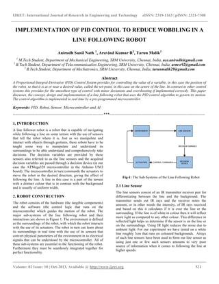
- 1. IJRET: International Journal of Research in Engineering and Technology eISSN: 2319-1163 | pISSN: 2321-7308 __________________________________________________________________________________________ Volume: 02 Issue: 10 | Oct-2013, Available @ http://www.ijret.org 531 IMPLEMENTATION OF PID CONTROL TO REDUCE WOBBLING IN A LINE FOLLOWING ROBOT Anirudh Sunil Nath 1 , Aravind Kumar R2 , Tarun Malik3 1 M.Tech Student, Department of Mechanical Engineering, SRM University, Chennai, India, ace.anirudh@gmail.com 2 B.Tech Student, Department of Telecommunication Engineering, SRM University, Chennai, India, armsr92@gmail.com 3 B.Tech Student, Department of Mechatronics, SRM University, Chennai, India, tarunmalik29@gmail.com Abstract A Proportional-Integral-Derivative (PID) Control System provides for controlling the value of a variable, in this case the position of the robot, so that it is at or near a desired value, called the set-point, in this case on the centre of the line. In contrast to other control systems this provides for the smoothest type of control with minor deviations and overshooting if implemented correctly. This paper discusses, the concept, design and implementation of a line following robot that uses the PID control algorithm to govern its motion. The control algorithm is implemented in real time by a pre-programmed microcontroller. Keywords: PID, Robot, Sensor, Microcontroller and AI ---------------------------------------------------------------------***------------------------------------------------------------------------- 1. INTRODUCTION A line follower robot is a robot that is capable of navigating while following a line on some terrain with the use of sensors that tell the robot where it is. Just as we manipulate and interact with objects through gestures, these robots have to be taught some way to manipulate and understand its surroundings to be able understand and comprehensively take decisions. The decision variables are provided by these sensors also referred to as the line sensors and the acquired decision variables are passed through a decision device (in our case the ATMega328 microcontroller in the Arduino UNO board). The microcontroller in turn commands the actuators to move the robot in the desired direction, giving the effect of following the line. A line in this case is a part of the terrain with a distinct colour that is in contrast with the background and is usually of uniform width. 2. ROBOT CONSTRUCTION The robot consists of the hardware (the tangible components) and the software (the control logic that runs on the microcontroller which guides the motion of the robot. The major sub-systems of the line following robot and their interactions are shown in Figure 1. The environment is defined as the surroundings of the robot, with which the robot interacts with the use of its actuators. The robot in turn can learn about its surroundings in real time with the use of its sensors that convert physical parameters of the environment in to electrical signals that can be understood by the microcontroller. All of these sub-systems are essential to the functioning of the robot. Furthermore they must be seamlessly integrated together for perfect functionality. Fig-1: The Sub-Systems of the Line Following Robot 2.1 Line Sensor The line sensors consist of an IR transmitter receiver pair for differentiating between the line and the background. The transmitter sends out IR rays and the receiver notes the amount, or in other words the intensity, of IR rays received and based on this it calculates if it is over the line or the surrounding. If the line is of white in colour then it will reflect more light as compared to any other colour. This difference in reflected light helps us determine if the sensor is on the line or on the surroundings. Using IR light reduces the noise due to ambient light. For our experiment we have tested on a white line roughly 3cm that runs on coloured backgrounds. Arrays of such line sensors have been used to form our line sensor as using just one or few such sensors amounts to very poor source of information when it comes to following the line at higher speeds.
- 2. IJRET: International Journal of Research in Engineering and Technology eISSN: 2319-1163 | pISSN: 2321-7308 __________________________________________________________________________________________ Volume: 02 Issue: 10 | Oct-2013, Available @ http://www.ijret.org 532 2.2 Decision Device Decision device is a unit where the decision variables passed by the line sensors are analysed, processed and then the appropriate actions/response are initiated. For our robot we have used the Arduino UNO microcontroller board and Arduino Programming Language for coding it. The PID control algorithm, discussed in the next section, is coded to this microcontroller. It is the brain of the robot and thus it can be said that the robot, to a certain degree, has artificial intelligence. 2.3 Actuators The actuators in this robot are brushed DC motors with a reduction gearbox that operate at 60 RPM and have sufficient torque to carry the robot. They are directly connected to the wheels of the robot and cause the robot to move in the desired direction. We have two motors controlling the two wheels. Motion is achieved using the concept of differential drive. Thus we can achieve motions of moving front, back and turning left and right. The motion is controlled from the microcontroller. The two motors are used to drive the robot using the concept of differential drive. In this the speed and direction of rotation of the individual wheels are used to both move and turn the robot. 2.4 Power Source The power source provides electrical power to the robot and all its components. It also consists of a set of regulators that provide the required voltages to the various parts of the robot. We choose a LiPo battery for this purpose because it has the highest power to weight ratio. Regulators are used to provide different levels of voltages for all the various components. 3. LINE FOLLOWING WITHOUT PID After construction of the robot we programmed it follow the line without the PID control algorithm. The method that was used was to check the sensor condition and according to that move the robot in the appropriate direction such that the robot tries to centre itself over the line this was repeated by the microcontroller hundreds of times a second. This was the implementation of a direct mapping of the sensor condition to the motion of the robot. The code was written so that the robot follows a black line on a white background. The result of this was that the robot followed the line. The deviations observed were immense. In certain cases the line sensors would all be off the line. This confused the robot since it did not correspond to any condition of the robot. The robot would continue in its last motion. This problem was solved by figuring out which direction the robot was moving when it moved off the line. This helped put it back on track. The bigger problem was to develop an algorithm that would allow the robot to follow the line smoothly even at high speed. The solution to this is to implement the PID control algorithm to control the motion of the robot. 4. LINE FOLLOWING WITH PID PID is widely used control algorithm, mostly used in industries, Robotics and other areas. The following is a brief explanation of PID. The PID algorithm is explained with taking a simple line following robot as an example, however its application may not be only limited by this. Our goal is to make the Robot follow the black line on the white surface. For it to follow the line with less number of errors and in a smooth manner we use PID Algorithm. It uses an IR sensor to detect the change in the colour of the place it is on. If it is a black, the sensor is on the line. If it is white, it is on the background. The sensor gives a HIGH value when it is on the black line & a LOW if it is on the white background. We can use any number of line sensors but for this example we will take 3 sensors into consideration. We will refer them as the Left, Middle & Right Sensor. First we will start off by describing the normal behavior of a robot while following a line. While the robot moves over the line it may come into the following conditions, if the line is detected by the Left Sensor, then the robot is programmed to go towards Left, if it is detected by the Right sensor, then it goes towards right and similarly for center position of the line it will go straight. The disadvantage in using this is that the robot may wobble a lot, and if going too fast then it may lose control and stop following the line, as discussed in the previous section. Fig -2: Comparison of robot with and without PID following a line
- 3. IJRET: International Journal of Research in Engineering and Technology eISSN: 2319-1163 | pISSN: 2321-7308 __________________________________________________________________________________________ Volume: 02 Issue: 10 | Oct-2013, Available @ http://www.ijret.org 533 When we introduce PID into the motion of Robot then it takes the following factors into consideration: the speed with which the robot is moving from side to side, is the robot centred over the line and how long the robot is not centred on the line. By introducing these, we can get a line following robot which will be very smooth in its motion and can follow it at high speeds as well. In Figure 2, we can see that the line following robot without PID follows the line with a lot of wobbling, whereas on the other hand the one with PID is much smoother as compared to the one without PID. The understanding of PID is necessary for its proper implementation. For this we need to look at the following terms. 4.1 Target Position (Set-Point) It is the required position for the robot to be in. For a line following robot, it is over the center of the line. It is set to zero. It is basically the mean position/the desired position. It is set as a set point in the program, and all the positions of the robot will be with respect to the target position. 4.2 Measured Position This is a value depending upon the position of the robot with respect to the line. It can either be positive or negative. It involves calculating the distance between the current position of the robot and the target position. It can either be to the right or to the left of the target position, and based on that it is given a positive or negative value. 4.3 Error This is the difference between the Target Position and the Measured Position. So the more far away the robot will be from the Target position, the more the value of the error. The magnitude of error depends on which side of the line the robot is in. This also has positive and negative values. 4.4 Proportional Component This component of the PID control, tells us how far away the robot is from the line. A sensor condition of 011 tells us the robot is closer to the line than the sensor position of 001. This component is proportional to the position of the robot with respect to the target position and proportionally varies the output speed of the robot to bring it back to its intended position. A high proportional value would require a large change in the output value, to correct the error. 4.5 Integral Component This component measures the error that builds up over time. This involves adding up the error after every step. The integral value keeps building up after every sensor scan cycle of the microcontroller. This is basically used to tell that the output given by the algorithm is not sufficiently changing the value of the error and the output given needs to be varied more drastically to reduce the error value. This is done for both positive and negative errors. 4.6 Derivative Component This component acts as the inverse of the integral component in the PID control algorithm. This component prevents the overshooting of the robot from the line when correcting the error. This means that when the error is reduces it stops the robot from moving so that it does not continue its motion to produce error by moving to the other side of the line. 4.7 PID Constants There are 3 constants used in this algorithm. These are the Proportional Constant (Kp), Integral Constant (Ki) and the Derivative Constant (Kd). The values of these constant are set beforehand by the programmer. The values of these constant depend on various thing ranging from weight of the robot to the size of it. The robot dimensions and the actuation system also play an important role in determining the value of these constants. 5. PID IMPLEMENTATION IN THE ROBOT For our robot, we used Arduino as the microcontroller board, with an ATMega328 on board. We initialized the various constants such as Kp, Ki and Kd. We also give a value to the Tp Variable, which is the maximum speed given to the wheels for straight condition. Also we initialize last error, which is the previous error value & other variables such as integral, derivative and proportional. We set the value of the Measured Position Variable for each sensor condition. These are the values we set are as in Table 1.
- 4. IJRET: International Journal of Research in Engineering and Technology eISSN: 2319-1163 | pISSN: 2321-7308 __________________________________________________________________________________________ Volume: 02 Issue: 10 | Oct-2013, Available @ http://www.ijret.org 534 Table -1: Value for Measured Position Sensor Measured Position Given Value 0-0-0 100 0-0-1 2 0-1-1 1 0-1-0 0 1-1-0 -1 1-0-0 -2 1-1-1 0 Then we calculated the error value as Error = Measured Value – Target Position A higher error value tells us that the robot is farther away from the line, than a lower error value. We then set the integral value as sum of current integral value & the error. The derivative value was updated to the sum of current derivative value & the last error. We then calculated TURN Value as the sum of the product of ERROR Value & the Kp constant, product of Ki constant and integral and the product of Kd constant & the derivative. We then give the output to the left wheel and the right wheel as a PWM (Pulse Width Modulation) output, which directly controls the speed of the motor. LeftPWM = Tp + TURN RightPWM = Tp – TURN This results in both the wheels moving at different speed, which depends on the sensor input and is computed above. At the end of the program we set the last error value as current error value. This algorithm keeps repeating in a loop to give an effective PID algorithm. The above explained computation happens many times in a second to give an efficient line following robot. Another essential part of a PID algorithm is the setting of the PID Constants, that are Kp, Ki and Kd values. The best way to determine the perfect constant value would be to start from 0, and then look for the best output after continuously incrementing them. From the program execution, the robot first checks the sensor input, and calculates the error accordingly. The error value tells us how far our robot is from the line. Then the derivative is calculated which tells us how fast are we moving towards or away from the line. The integral is then calculated which sums up the distance from the line’s edge. Using this TURN value is calculated which is added to the PWM values of the wheel. PID can be further improved by increasing the number of sensors, which would cause the robot to go faster at curves and follow it more efficiently. The reason to this is that at curves the corner sensors will sense the line and proportionally are able to come back to the line, whereas for lesser number of sensors the robot may just come off the line. CONCLUSIONS Before using the PID, the problem we faced were that the robot did not follow the line smoothly. It wasn’t efficiently following the line, so to improve this we implemented the PID logic. We started with implementing the proportional part, and wrote down the code for it. After running the robot we noticed that while following the wobbling of the robot was lesser than before, but it was still a big issue. We then added the integral part to the code, and the robot was now following the line much more efficiently with very less wobbling. The line following was further improved after adding the differential part to the code, which reduced the overshooting of the robot while trying to return to the line. The robot developed and used for testing by us is shown in Figure 3. While implementing PID, we faced a major problem in setting up the constants for the Proportional, Integral and Differential. We started by setting each value as 1 and then made the changes by either increasing it or decreasing it, and seeing the changes in the behavior of the robot. The constants had to be changed to many times before arriving at the perfect values. After setting up P constant, and setting the Integral Constant, even the P constant had to be varied a little. Fig-3: The Robot REFERENCES [1]. Electrical Power Systems by Wadhwa C L [2]. Modern Control Systems by Richard C Dorf and Bishop [3]. Robotics modeling planning and control by Bruno Siciliano, Lorenzo Sciavicco, Luigi Villani, Giuseppe Oriolo.
- 5. IJRET: International Journal of Research in Engineering and Technology eISSN: 2319-1163 | pISSN: 2321-7308 __________________________________________________________________________________________ Volume: 02 Issue: 10 | Oct-2013, Available @ http://www.ijret.org 535 [4]. Robot Buildings for Beginners by David Cook BIOGRAPHIES Anirudh is currently pursuing his M.Tech in Robotics from SRM University, Chennai. His area of interest is AI and Robotics Aravind is currently pursuing his B.Tech in Telecommunication Engineering from SRM University, Chennai. Area of interest is Robotics and Networking. Tarun is currently pursuing his B.Tech in Mechatronics from SRM University. His area of interest is Robotics and Machine Learning.