IRJET - Analysis of Rejection of Square Piston and its Remedies
•
0 likes•8 views

https://www.irjet.net/archives/V7/i3/IRJET-V7I3671.pdf

Recommended
Recommended
More Related Content
What's hot
What's hot (6)
Similar to IRJET - Analysis of Rejection of Square Piston and its Remedies
Similar to IRJET - Analysis of Rejection of Square Piston and its Remedies (20)
More from IRJET Journal
More from IRJET Journal (20)
Recently uploaded
Recently uploaded (20)
IRJET - Analysis of Rejection of Square Piston and its Remedies
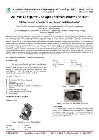
- 1. International Research Journal of Engineering and Technology (IRJET) e-ISSN: 2395-0056 Volume: 07 Issue: 03 | Mar 2020 www.irjet.net p-ISSN: 2395-0072 © 2020, IRJET | Impact Factor value: 7.34 | ISO 9001:2008 Certified Journal | Page 3336 ANALYSIS OF REJECTION OF SQUARE PISTON AND ITS REMEDIES S. Jeffrey Melvin1, V. Karthik2, S. Janarthanan3, Mr. K. Balachandar4 1,2,3B.E Student, Department of Mechanical Engineering, Prathyusha Engineering College, Tamil Nadu, Chennai – 602025 4Assisstant Professor, Department of Mechanical Engineering, Prathyusha Engineering College, Tamil Nadu, Chennai 602025 ------------------------------------------------------------------------------------------------***--------------------------------------------------------------------------------------------- Abstract: In current trends improving and increasing the productivity of the product is very essential to survive in the markets in case of any successful company. The understanding of the quality system must be done in a better methodology. The product variation and the process operational cost can be reduced by improving the method of optimization in terms of the quality method. In order to reduce the rejection rate as well as to give suggestions for improvement of the product we intend to apply quality control tools in the stages of the production process. In terms of any manufacturing company the company faces crisis in terms of having the part rejected after the process of manufacturing which both directly and indirectly affects the cost of the company. Companies may suffer deliberately from problems especially from high rejection as well as rework in the production processing lines. The various process parameters such as the machining operations, grinding, workpiece material etc. influence the product to be controlled and have high aspects in term of the quality of the product as well as give a brief improvement over the process. The common goal in any industry is to reduce the rejection. The process of rejection analysis helps in the identification of the problems that occur with quality as well as the production of the components in an industry which serves as an important key point in terms of the manufacturing processes. Keywords: Rejection, Quality, Production, Manufacturing. INTRODUCTION The seven tools of quality can be used where they can provide the significant cause as well as to identify the various methods, steps, process as well as the introduction of new solution for the probable cause. These tools are enlisted and is used highly in terms of quality as well as maintaining standards of the company as well as the product. The seven QC tools are: 1. Stratification (Divide and Conquer) 2. Histogram 3. Check Sheet (Tally Sheet) 4. Cause-and-effect diagram (“fishbone” or Ishikawa diagram) 5. Pareto chart (80/20 Rule) 6. Scatter diagram (Shewhart Chart) 7. Control chart PISTON FOR HYDRAULIC PUMPS SQUARE PISTON Figure 1 SQUARE PISTON AFTER ASSEMBLY Finishing - Polished Use - For Tractor Product Type - Piston Material - Cast Iron Part Type - Pump Part Surface Treatment - Coated Weight - 50-150 Grams (g) Figure 2 PISTON AFTER CASTING Figure 3 PISTON AFTER MACHINING PROCESSES FLOW CHART Flow Chart is one of the primary tools of the New Quality Tools Where the various process as well as the method are identified using a flow model for clear understanding. The flow chart is used to identify the various stages as well as the process nature and its timeline.
- 2. International Research Journal of Engineering and Technology (IRJET) e-ISSN: 2395-0056 Volume: 07 Issue: 03 | Mar 2020 www.irjet.net p-ISSN: 2395-0072 © 2020, IRJET | Impact Factor value: 7.34 | ISO 9001:2008 Certified Journal | Page 3337 Figure 4 Piston After Manufacturing FLOW CHART IN PRODUCT MANUFACTURING Figure 5 FLOW CHART OF MANUFACTURING FLOW CHART IN MILLING PROCESS Figure 6 FLOW CHART OF MILLING MACHINE Figure 7 COMPONENT AFTER MACHINING PROCESS FLOW CHART IN BROACHING PROCESS Figure 8 FLOW CHART OF BROACHING PROCESS FIGURE 23 COMPONENT AFTER BROACHING PROCESS Fixating Workpiece in the Fixture Milling Process on the Arm Face Drilling on the face of the Arm Unclamping of Workpiece and Removal of Burrs Fixating the Workpiece into the fixture Broaching is done on the internal side of the Piston Removal of Workpiece and Cleaning of Burrs Supplier Raw Material Company Storage Face Milling Process Broaching Process Deburring Process Arm Milling & Drilling Process CNC Turning Process Centreless Grinding Process Dispatch
- 3. International Research Journal of Engineering and Technology (IRJET) e-ISSN: 2395-0056 Volume: 07 Issue: 03 | Mar 2020 www.irjet.net p-ISSN: 2395-0072 © 2020, IRJET | Impact Factor value: 7.34 | ISO 9001:2008 Certified Journal | Page 3338 FLOW CHART IN DEBURRING PROCESS Figure 9 FLOW CHART OF DEBURRING PROCESS Figure 10 COMPONENT AFTER DEBURRING PROCESS FLOW CHART IN TURNING PROCESS Figure 11 FLOW CHART OF TURNING PROCESS Figure 12 COMPONENT AFTER TURNING PROCESS FLOW CHART IN GRINDING PROCESS Figure 13 FLOW CHART OF GRINDING PROCESS The Hydraulic Pump used in tractors is one of the major components that is manufactured in Cross Manufacturing Company. The Data Collected in the months of May, July And September shows that the most rejected part is the Piston Hydraulic Pump, Hence We use the Pareto Diagram to determine the various Rejection of Components that has been done in the piston machining line. Pareto Analysis is a statistical technique in decision-making used for the selection of a limited number of tasks that produce significant overall effect. It uses the Pareto Principle (also known as the 80/20 rule) the idea that by doing 20% of the work you can generate 80% of the benefit of doing the entire job. Take quality improvement, for example, a vast majority of problems (80%) are produced by a few key causes (20%). This technique is also called the vital few and the trivial many. REJECTION OF COMPONENTS In order to reject the various defective components produced by the company the company uses the paretto analysis ,paretto analysis is done on the defects produced by the each machine used for production in the last 3 months A comprehensive study was done on the number of rejected components by each and every machine used for production and the number of components staggered in one particular product which became the focus of this rejection analysis project The piston was the front runner of the most defective components with 58 components being rejected in the last three months ,with cup gear shift being a close second with 24 components. The differential cross produced 15 rejected components ,the center column ,shaft differential cross each producing 13 rejected components each ,couple rear drive creating 11 defects in its production and shaft lower link having the least number of component being rejected having only 6 in its tally. Type of component Number of defects Hydraulic piston 58 Cup gear shift 24 Differential cross 15 Center column 13 Shaft differential cross 13 Deburring the External Edges of the Workpiece Deburring the Internal edges of the Workpiece Repeating the process on the other face of the Workpiece Loading of Workpiece by the Drilled Centres Step Turning and grooving on the circumference of the arm UnLoading and Removing the Burrs Loading the Workpiece into the Machine Grinding the circumference of the Arm Unloading and Inspection
- 4. International Research Journal of Engineering and Technology (IRJET) e-ISSN: 2395-0056 Volume: 07 Issue: 03 | Mar 2020 www.irjet.net p-ISSN: 2395-0072 © 2020, IRJET | Impact Factor value: 7.34 | ISO 9001:2008 Certified Journal | Page 3339 Couple rear Drive 11 Shaft lower link 6 Table 1 Types of Components Upon The various components that have been manufactured the manufacturing of the piston is made with the greater number of rejections hence we select that particular component to reduce its rejection by analyzing the various causes of Rejection and to come up with a solution to reduce the rejection rate thereby providing Zero Defect as well as reducing the cost that has been used in production of the defective part. Figure 14 Pareto in types of components Figure 15 Pareto in Various defects
- 5. International Research Journal of Engineering and Technology (IRJET) e-ISSN: 2395-0056 Volume: 07 Issue: 03 | Mar 2020 www.irjet.net p-ISSN: 2395-0072 © 2020, IRJET | Impact Factor value: 7.34 | ISO 9001:2008 Certified Journal | Page 3340 Figure 16 Pareto in various machines Based Upon the Data Collected From the month of May, July & September the pareto Diagram has been constructed to determine the various Defects Produced in the various Machining Machines. Type of machines No of components Cnc turning machine 28 Arm milling machine 21 Face milling machine 19 Centerless grinding macjine 6 Table 2 Types of machines It is observed that the cnc turning machine saw the most number of rejection adding to 38 percent of all the rejection of components ,the second machine which witnessed the most rejection was arm milling machine ,it can be inferred that some of the defects can be carried over to cnc turning machine from this machine adding up to 21 components rejected but also 32 percent of the total rejected components,the third machine which has the most rejections is face milling machine with 19 components being rejected during the three months this record was taken with total percentage of components rejected from this machine amassing around 19 percent of the total component rejected, the centerless grinding machine has the least rejection with only 6 components adding up the final 9 percent of the total Figure 17 Pareto in Face milling Upon Further Analyzing the statistics ,The Rejection in the Face Milling Operation is reasoned by two factors namely milling width minus and Milling Taper Type of defects No of components Milling width minus 11 Milling taper 8 Table 3 Defects in milling process During the three months face milling machine saw a total rejection of 18 components with a whooping lion share of defects coming from milling width minus defect rejecting a total of 11 components adding up to 55 perecent of the total percentage of components rejected, and the second type of defect namely milling taper rejecting its share of 8 components to its tally and contributing a total of 45 percent of total number of percentage of rejected components.
- 6. International Research Journal of Engineering and Technology (IRJET) e-ISSN: 2395-0056 Volume: 07 Issue: 03 | Mar 2020 www.irjet.net p-ISSN: 2395-0072 © 2020, IRJET | Impact Factor value: 7.34 | ISO 9001:2008 Certified Journal | Page 3341 Figure 18 Pareto in arm milling The Rejection In Arm Milling is reasoned by Only one factor which is Centre drill offset where whooping 21 Components have been rejected in the statistical analysis All the 100 percent of rejection in arm milling came from centre drill offset defect. Figure 19 Pareto in turning machine The Rejected Piston Components saw the highest percentage of rejection in CNC Turning Machine and the reason for rejection stems from three factors namely Groove position shift, CNC Outer Diameter Minus and Outer Diameter Lobbing. Type of defect No of component rejected Groove position shift 14 Cnc outer diameter minus 12 Outer diameter lobbing 2 Table 4 Defect in Turning machine Three type of defects dominate the cnc turning machine ,with the groove position shift defect rejected around 14 components during the three month period and contributing to a 50 percent of total percentage of total number of rejection percentage and the second close competitor of this defect being rejecting only 2 component less than the former being cnc outer diameter minus having rejected 12 components and adding a total rejection percentage of 42 and that gives us to the introduction of the third defect in the cnc turning machine being outer diameter lobbing rejecting a total pf only 2 components and adding to the final 8 percent of the total rejection percentage Figure 20 Pareto in Grinding machine
- 7. International Research Journal of Engineering and Technology (IRJET) e-ISSN: 2395-0056 Volume: 07 Issue: 03 | Mar 2020 www.irjet.net p-ISSN: 2395-0072 © 2020, IRJET | Impact Factor value: 7.34 | ISO 9001:2008 Certified Journal | Page 3342 The Rejected Piston Components saw the least percentage of rejection in Centerless grinding Machine with grinding ovality and CNC Grinding Outer Diameter Minus rejected one and five components respectively. Type of defects No of components Cnc grinding outer diameter minus 5 Grinding ovality 1 Table 5 Defect in grinding machine Even the machine with least rejection , has given rise to two different type of defects them being cnc grinding outer diameter minus and grinding ovality, with the former rejecting up to 5 components being the total 80 percent of the rejected components and the latter rejecting only a single component adding up to 20 percent of the total components rejected ISHIKAWA The fishbone diagram or Ishikawa diagram is a cause- and-effect diagram that helps managers to track down the reasons for imperfections, variations, defects, or failures. The diagram looks just like a fish’s skeleton with the problem at its head and the causes for the problem feeding into the spine. Once all the causes that underlie the problem have been identified, managers can start looking for solutions to ensure that the problem doesn’t become a recurring one. Finally, the fishbone diagram is also a great way to look for and prevent quality problems before they ever arise. Use it to troubleshoot before there is trouble, and you can overcome all or most of your teething troubles when introducing something new. Figure 21 Ishikawa in Piston Defects CONTROL CHART The control chart is a graph used to study how a process changes over time. Data are plotted in time order. A control chart always has a central line for the average, an upper line for the upper control limit, and a lower line for the lower control limit. These lines are determined from historical data. By comparing current data to these lines, you can draw conclusions about whether the process variation is consistent (in control) or is unpredictable (out of control, affected by special causes of variation). This versatile data collection and analysis tool can be used by a variety of industries and is considered one of the seven basic quality tools. Control charts for variable data are used in pairs. The top chart monitors the average, or the centering of the distribution of data from the process. The bottom chart monitors the range, or the width of the distribution. If your data were shots in target practice, the average is where the shots are clustering, and the range is how tightly they are clustered. Control charts for attribute data are used singly.
- 8. International Research Journal of Engineering and Technology (IRJET) e-ISSN: 2395-0056 Volume: 07 Issue: 03 | Mar 2020 www.irjet.net p-ISSN: 2395-0072 © 2020, IRJET | Impact Factor value: 7.34 | ISO 9001:2008 Certified Journal | Page 3343 CONTROL CHART FOR HOLE DIAMETER FOR DRILLING Date Sample measure s Mean UCL(3σ ) LCL(3σ ) 2/12/2019 15.059 15.050 15.100 15.000 3/12/2019 15.059 15.050 15.100 15.000 4/12/2019 15.069 15.050 15.100 15.000 5/12/2019 15.047 15.050 15.100 15.000 6/12/2019 15.033 15.050 15.100 15.000 9/12/2019 15.045 15.050 15.100 15.000 10/12/2019 15.055 15.050 15.100 15.000 11/12/2019 15.053 15.050 15.100 15.000 12/12/2019 15.049 15.050 15.100 15.000 13/12/2019 15.063 15.050 15.100 15.000 14/12/2019 15.059 15.050 15.100 15.000 16/12/2019 15.043 15.050 15.100 15.000 17/12/2019 15.05 15.050 15.100 15.000 18/12/2019 15.039 15.050 15.100 15.000 19/12/2019 15.049 15.050 15.100 15.000 20/12/2019 15.058 15.050 15.100 15.000 21/12/2019 15.052 15.050 15.100 15.000 23/12/2019 15.051 15.050 15.100 15.000 24/12/2019 15.06 15.050 15.100 15.000 26/12/2019 15.047 15.050 15.100 15.000 27/12/2019 15.049 15.050 15.100 15.000 28/12/2019 15.05 15.050 15.100 15.000 29/12/2019 15.049 15.050 15.100 15.000 30/12/2019 15.058 15.050 15.100 15.000 31/12/2019 15.05 15.050 15.100 15.000 MEAN 15.052 STANDARD DEVIATION 0.007803204 Table 6 Control Chart for hole diameter The above control chart is an example of the diameter of the hole to be drileed at the face of the arms of the piston. The x-axis denotes the day of the month for the particular observations while the y-axis deals with the quality characteristics i.e. the dimensions of the part. The average of the above samples is 15.050 which means measures an average 15.050 each day. The control limits are then calculated. The UCL is 15.100mm. The LCL is 15.000mm. This is the minimum allowable measurement acceptable when only common causes are present. There is one point beyond the UCL. This is the first pattern that signifies an out of control point a special cause of variation. Special causes of variation are detected on control charts by noticing certain types of patterns that appear on the control chart. controlits is one such pattern. Figure 22 Control chart for hole diameter CONTROL CHART FOR CENETERLESS GRINDING FINISH Date Sample measures Mean UCL(3 σ) LCL(3 σ) 12-02- 2019 25.047 25.051 25.057 25.045 12-03- 2019 25.049 25.051 25.057 25.045 12-04- 2019 25.056 25.051 25.057 25.045 12-05- 2019 25.05 25.051 25.057 25.045 12-06- 2019 25.049 25.051 25.057 25.045 12-09- 2019 25.049 25.051 25.057 25.045 12-10- 2019 25.053 25.051 25.057 25.045 12-11- 2019 25.053 25.051 25.057 25.045 12-12- 2019 25.051 25.051 25.057 25.045 13/12/20 19 25.055 25.051 25.057 25.045 14/12/20 19 25.053 25.051 25.057 25.045 16/12/20 19 25.047 25.051 25.057 25.045 17/12/20 19 25.049 25.051 25.057 25.045 18/12/20 19 25.052 25.051 25.057 25.045 19/12/20 19 25.051 25.051 25.057 25.045 20/12/20 19 25.05 25.051 25.057 25.045 21/12/20 19 25.049 25.051 25.057 25.045
- 9. International Research Journal of Engineering and Technology (IRJET) e-ISSN: 2395-0056 Volume: 07 Issue: 03 | Mar 2020 www.irjet.net p-ISSN: 2395-0072 © 2020, IRJET | Impact Factor value: 7.34 | ISO 9001:2008 Certified Journal | Page 3344 23/12/20 19 25.056 25.051 25.057 25.045 24/12/20 19 25.047 25.051 25.057 25.045 26/12/20 19 25.047 25.051 25.057 25.045 27/12/20 19 25.051 25.051 25.057 25.045 28/12/20 19 25.053 25.051 25.057 25.045 29/12/20 19 25.055 25.051 25.057 25.045 30/12/20 19 25.051 25.051 25.057 25.045 31/12/20 19 25.055 25.051 25.057 25.045 MEAN 25.051 STANDAR D DEVIATIO N 0.0028913 66 Table 7 Control chart for Grinding The above control chart is an example of the finishing dimensions in the final process piston manufacturing which is centerless grinding. The x-axis denotes the day of the month for the particular observations while the y-axis deals with the quality characteristics i.e. the dimensions of the part. The average of the above samples is 25.051 which means measures an average 25.051 each day. The control limits are then calculated. The UCL is 25.057mm. The LCL is 25.045 mm. This is the minimum allowable measurement acceptable when only common causes are present. There is one point beyond the UCL. This is the first pattern that signifies an out of control point a special cause of variation. Special causes of variation are detected on control charts by noticing certain types of patterns that appear on the control chart. The point be-yond the control limits Figure 23 Control Chart for finish CONTROL CHART FOR GROOVE LENGTH Date Sample measures Mean UCL(3σ ) LCL(3σ ) 2/12/2019 28.12 28.015 28.140 27.890 3/12/2019 27.93 28.015 28.140 27.890 4/12/2019 27.92 28.015 28.140 27.890 5/12/2019 28.05 28.015 28.140 27.890 6/12/2019 28.012 28.015 28.140 27.890 9/12/2019 27.93 28.015 28.140 27.890 10/12/2019 27.99 28.015 28.140 27.890 11/12/2019 28.04 28.015 28.140 27.890 12/12/2019 28.12 28.015 28.140 27.890 13/12/2019 27.97 28.015 28.140 27.890 14/12/2019 28 28.015 28.140 27.890 16/12/2019 27.93 28.015 28.140 27.890 17/12/2019 27.9 28.015 28.140 27.890 18/12/2019 27.99 28.015 28.140 27.890 19/12/2019 28.1 28.015 28.140 27.890 20/12/2019 28.13 28.015 28.140 27.890 21/12/2019 28.13 28.015 28.140 27.890 23/12/2019 28.1 28.015 28.140 27.890 24/12/2019 27.85 28.015 28.140 27.890 26/12/2019 27.92 28.015 28.140 27.890 27/12/2019 28.02 28.015 28.140 27.890 28/12/2019 28 28.015 28.140 27.890 29/12/2019 27.99 28.015 28.140 27.890 30/12/2019 27.99 28.015 28.140 27.890 31/12/2019 28.12 28.015 28.140 27.890 MEAN 28.015 STANDARD DEVIATION 0.08175263 5 Table 8 Control chart for groove length
- 10. International Research Journal of Engineering and Technology (IRJET) e-ISSN: 2395-0056 Volume: 07 Issue: 03 | Mar 2020 www.irjet.net p-ISSN: 2395-0072 © 2020, IRJET | Impact Factor value: 7.34 | ISO 9001:2008 Certified Journal | Page 3345 The above control chart is an example of the groove length tolerance that should be maintained in the turning operation. Figure 24 Control Chart for groove length The x-axis denotes the day of the month for the particular observations while the y-axis deals with the quality characteristics i.e. the dimensions of the part. The average of the above samples is 28.015which means measures an average 28.015 each day. The control limits are then calculated. The UCL is 28.140mm. The LCL is 27.890mm. This is the minimum allowable measurement acceptable when only common causes are present. There is one point beyond the UCL. This is the first pattern that signifies an out of control point a special cause of variation. Special causes of variation are detected on control charts by noticing certain types of patterns that appear on the control chart. The point be-yond the control limits of such pattern. CONTROL CHART FOR BROACHING FINISH WIDTH Date Sample measures Mean UCL(3σ ) LCL(3σ ) 2/12/2019 58.973 58.995 59.020 58.970 3/12/2019 58.975 58.995 59.020 58.970 4/12/2019 58.98 58.995 59.020 58.970 5/12/2019 59.015 58.995 59.020 58.970 6/12/2019 59.001 58.995 59.020 58.970 9/12/2019 58.994 58.995 59.020 58.970 10/12/2019 58.996 58.995 59.020 58.970 11/12/2019 58.996 58.995 59.020 58.970 12/12/2019 58.996 58.995 59.020 58.970 13/12/2019 58.995 58.995 59.020 58.970 14/12/2019 58.999 58.995 59.020 58.970 16/12/2019 58.989 58.995 59.020 58.970 17/12/2019 58.996 58.995 59.020 58.970 18/12/2019 58.971 58.995 59.020 58.970 19/12/2019 58.995 58.995 59.020 58.970 20/12/2019 58.995 58.995 59.020 58.970 21/12/2019 58.993 58.995 59.020 58.970 23/12/2019 58.981 58.995 59.020 58.970 24/12/2019 59.005 58.995 59.020 58.970 26/12/2019 59.001 58.995 59.020 58.970 27/12/2019 58.997 58.995 59.020 58.970 28/12/2019 58.994 58.995 59.020 58.970 29/12/2019 58.997 58.995 59.020 58.970 30/12/2019 58.995 58.995 59.020 58.970 31/12/2019 58.997 58.995 59.020 58.970 MEAN 58.993 STANDARD DEVIATION 0.01006429 3 Tabel 9 Control chart for broaching The above control chart is an example of the finishing dimensions in the width of the broaching machine in the broaching machine. The x-axis denotes the day of the month for the particular observations while the y-axis deals with the quality characteristics i.e. the dimensions of the part. The average of the above samples is 25.051 which means measures an average 25.051 each day. The control limits are then calculated. The UCL is 25.057mm. The LCL is 25.045 mm. This is the minimum allowable measurement acceptable when only common causes are present. There is one point beyond the UCL. This is the first pattern that signifies an out of control point a special cause of variation. Special causes of variation are detected on control charts by noticing certain types of patterns that appear on the control chart. The point be- yond the control limits Figure 25 Control chart for broaching
- 11. International Research Journal of Engineering and Technology (IRJET) e-ISSN: 2395-0056 Volume: 07 Issue: 03 | Mar 2020 www.irjet.net p-ISSN: 2395-0072 © 2020, IRJET | Impact Factor value: 7.34 | ISO 9001:2008 Certified Journal | Page 3346 ROOT CAUSE ANALYSIS Eventually all manufacturing processes will experience problems with non-conforming parts, equipment failure resulting in lost productivity or rework expenses and possible increased scrap. Even with the best quality systems, training and Statistical Process Control (SPC), problems can happen. What must be prevented are the repeat problems. The problems you thought were resolved only to reoccur. Repeat problems can be experienced in everyday life. If you compare a manufacturing process to a garden, the process problems would be the weeds in the garden. If you pull up a dandelion and don’t get the entire root it will just keep popping back up. It is much the same with manufacturing problems – if you don’t get to the root cause of the problem, it is eventually (if not frequently) going to re-occur. The goal of a Root Cause Analysis (RCA) is to get down to the true cause of the problem, the root cause. Root Cause Analysis for Centre Drill Offset Defect Figure 26 Root cause for Drill Offset Root Cause Analysis of Milling Width Minus Figure 27 Root Cause for Milling Width Root Cause Analysis of Centerless grinding Outer Diameter Minus Figure 28 Root Cause for grinding Diameter Centre Drill Offset Tool- Workpiece Offset Shift Wobble of workpiece during machining Improper clamping of workpice Bolt of clamp for workpiece is loose Incompletion of tightening of bolt by bolt tightening machine Carelessness of operator Milling Width minus Depth of cut is high Incorrect cutting parameters Invasion of burr in cutting process Cutting edge of toool is chipped Prolonged use of tool than tool life Improper tool monitoring Grinding Outer Diameter Minus Grinding burns and surface irregularities Lubrication is not sufficient More heat is generated during grinding High infeed Training the operator before enrolling them to work as well as
- 12. International Research Journal of Engineering and Technology (IRJET) e-ISSN: 2395-0056 Volume: 07 Issue: 03 | Mar 2020 www.irjet.net p-ISSN: 2395-0072 © 2020, IRJET | Impact Factor value: 7.34 | ISO 9001:2008 Certified Journal | Page 3347 Root Cause Analysis of Milling Taper Figure 29 Root Cause for milling Taper RESULTS CAUSE TYPE CAUSES MEASURES Operator skill ( man) Due to absence of skill chances of accidents at operation station is more Operator should provide with sufficient training Operator awareness (man) Operator is not locating the part properly on gauge. Specified tolerance limit may vary due to Negligence Operator should be trained regarding slight changes in part specification may affect quality Material properties (material) Poor material properties leads to Crack and damages Material should be ductile enough to absorb pressure at peaks and not shatters Metal Chips present on the chucks and tool ( method) Metal Chips present on the chucks and tool ( method) Make sure that chips are removed properly Grinding outer diameter minus (method) High infeed of the cutting tool Infeed rate should be mitigated and should be paralel to the coolant supply Milling width minus (method) Incorrect cutting tool parameters fed in to the cnc machine Tool parameters and its tool life must be monitored periodically by tool monitoring system or manual inspection Centre drill offset defect (man) Improper clamping of work piece Training the operator on the job as well as testing the components Milling taper defect(man) Work piece elevated inclination with respect to tool Positioning and fixing of the fixture And removing the burs using air gun Tool indexing(method) Wrong position of tool will damage the piston Tool has to be accurately set Speed (machine) Improper machining on Operator should follow Milling taper Workpiece elevated inclination with respect to tool Presence of burr in the machine bed Non Removal of Burrs Operator Carelessness
- 13. International Research Journal of Engineering and Technology (IRJET) e-ISSN: 2395-0056 Volume: 07 Issue: 03 | Mar 2020 www.irjet.net p-ISSN: 2395-0072 © 2020, IRJET | Impact Factor value: 7.34 | ISO 9001:2008 Certified Journal | Page 3348 the surface of piston the SOP strictly Tool grinding (method) leads to deep cut or improper surface finishing Tool has to be grind or changed whenever its necessary Blow holes Due to excessive gas content in the metal bar and rejection of dissolved gases during solidification,it includes hydrogen and nitrogen detect before machining, requiring harmonic, ultrasonic, magnetic or x- ray analysis. Table 10 Findings and Results From the above table it can be seen that the several problems associated with the hydraulic piston are studied and the feasible solutions are also derived by our knowledge. After studying all problems related to each research papers individual solutions are provided. Based on solution on that problem effect on production is changed as increase in productivity or reduction of rejection rates. CONCLUSION In the earlier days traditional Quality Control techniques such as hit and trial or thumb rule are not guided by scientific principle or rules but follow an unsystematic approach leading to wastage of time, improper utilization of resources and ineffective solutions. These techniques do not provide optimum solutions but only provide a shortcut whose effectiveness is not guaranteed. Quality Problem Solving Analysis using various quality tools such as why why analysis, Frequency Sheets, control chart, Pareto Chart and Cause and Effect Diagram, it can be concluded that these scientific problem solving techniques are far better and efficient as well as provide systematic approach towards problem solving as compared to traditional quality control techniques used in Indian Industries leading to overall improvement in productivity.- Minimization of defect and rework is an important factor ensuring the quality of product. The importance of manufacturing industry in the economy is high. So manufacturing the quality product is essential to sustain in the global market. Customer satisfaction depends on quality of product. Good quality results in good establishment of brand name, good providers and builds reputation in market. We should know that 1 % defect leads to 100% defective for customer to buy product. RECOMMENDATIONS Make Use of Poke Yoke Method, where without the application of the first the second stage does not undergo which minimizes the overall method rejection without need of analysis. Go and No-Go Gauges must be embedded with PLC Circuits such that before loading of the components the workpiece must be measured whether it has the required parameters of design. This prevents the defective material to be manufactured and reduces the total power and resources required. A separate division must be made such that the rejected and rework materials so that those are to be made as functioning workpiece so that material reductions can be achieved. Every Machine must have a Check, Lubricate and Inspect Chart (CLI) and before the start of the machine must be thoroughly checked with the chart such that maintenance can be done accordingly and helps in increasing the efficiency and the life of the machines. Machine Calibration must be labeled and maintained both on the machine and on a separate module such that efficient functioning can be maintained. The machine line must have a supply quality stage to check the casting material as well as a Final Quality stage to check whether the components can be supplied to the desired customers. The final Quality Stage must determine that the component has been manufactured with both dimensional as well as surface tolerances. Each machine must be embedded with the PLC and a Central server such that a component can be only moved in case if the same component was successfully finished the earlier stages. Weekly as well as monthly audit must be correspondingly done to check the quality as well as the ways to prevent defects and achieve zero defects.
- 14. International Research Journal of Engineering and Technology (IRJET) e-ISSN: 2395-0056 Volume: 07 Issue: 03 | Mar 2020 www.irjet.net p-ISSN: 2395-0072 © 2020, IRJET | Impact Factor value: 7.34 | ISO 9001:2008 Certified Journal | Page 3349 Quality of the product must be focused more than the Quantity of the product that has been manufactured. A respective span must be given for the use of coolants as well as tooling oils and they must be changed at equal intervals of time. The workstation mut be cleaned thoroughly for after a definitive number of components manufactured such that they are free from the burs that might affect the tools. The tool Calibration as well as the sharpness must be maintained and checked periodically. In case of safety the machines must be equipped with a sensor such that if they bring the hands while the machine is in operation it would automatically stop thereby preventing causalities. The sensors must be accurate and moreover digital sensors with clear dimension listing must be used to derive the accurate values. In case of VMC and CNC machine the programs must be set such that it corresponds to the home position of both the tool as well as the workpiece. A barcode system for the components must be introduced for making the embedded system with a central server more easy and job perfection. Operators must undergo training and must be able to understand the full concepts of the manufacturing process of the component as well as the working of the machines along with manual visual inspection. [1] Dias, S., & Saraiva, P. M. (2004). Use Basic Quality Tools To Manage Your Processes’. Quality Progress, 37(8), p47–53. [2] Escalante, E. J. (1999). Quality and productivity improvement: a study of variation and defects in manufacturing. Quality Engineering, 11(3), 427–442. [3] Evans, J. E., & Lindsay, W., M. (2004). The Management and Control of Quality (6 edition). Mason, OH: South-Western College Pub. [4] Ishikawa, K. (1988). What is Total Quality Control? the Japanese Way. (D. J. Lu, Trans.) (1St Edition edition). Englewood Cliffs, N.J: Prentice Hall. [5] Kume, H. (1987). Statistical Methods for Quality Improvement. Tokyo: Productivity Press. [6] Magar, V. M., & Shinde, V. B. (2014). Application of 7 Quality Control (7 QC) Tools for Continuous Improvement of Manufacturing Processes. International Journal of Engineering Research and General Science, 2(4), 364–371. [7] Mears, P. (1994). Quality Improvement Tools & Techniques. New York: McGraw-Hill Trade. [8] Montgomery, D. (2012). Statistical Quality Control (7 edition). Hoboken, NJ: Wiley. [9] Paliska, G., Pavletiæ, D., & Sokoviæ, M. (2008). Application of quality engineering tools in process industry. International Journal Advanced Engineering,(ISSN 1846-5900), 2(1), 79–86. [10] Sarkar, A. (1998). Implementation of ISO 9000 in a textile mill. Total Quality Management, 9(1), 123–131. REFERENCES