Heat Load Calculation and HVAC Design for Hospital Using Revit
•
0 likes•12 views

https://www.irjet.net/archives/V10/i4/IRJET-V10I430.pdf
![International Research Journal of Engineering and Technology (IRJET) e-ISSN: 2395-0056
Volume: 10 Issue: 04 | Apr 2023 www.irjet.net p-ISSN: 2395-0072
© 2023, IRJET | Impact Factor value: 8.226 | ISO 9001:2008 Certified Journal | Page 199
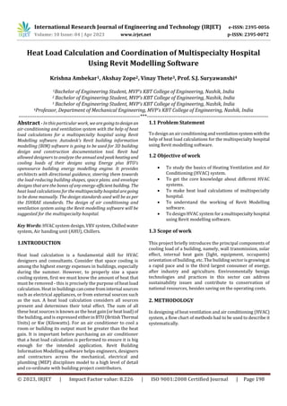
The steps include:
Fig-1: Methodology Flow Chart
3. LITERATURE REVIEW
Sharad Shukla et. al. [1] have designed the energy efficient
HVAC system for a school building. The use of air
conditioning systems for residential/office buildings were
very minimum in the earlier days of 1980’s. Due to the
technology advancement and industrial growth buildings
were started construction in a closed area and construction
of apartment also increased after 1980’s with increased
population. Also, ambient temperatures are changed
drastically due to global warming effect. The necessity of
design of air conditioning system for residential/office
buildings is increasing day-by-day and lot of professionals
have been developed in this field and adapted themselves
into this field as consultants/designers due to the increased
requirement. Hence, they also felt necessity to learn this
subject and upgrade their knowledge in this field of air
conditioning.
Ren Lu-luet. et. al. [2] have designed an office building in
Nanjing as an example to use the BIM technology for the 3-
dimensional optimization. With the detailed layout of
pipelines, it sets the elevation to replan the original
unreasonable designing.
V. Nikithaet. et.al. [3] have discussed the cooling load
calculations for a commercial building by using Revit
software. Window air conditioners, splitairconditionersare
used in small buildings and offices etc but in big buildings
and commercial complex we use central air conditioning
systems these systems are installed far away from the
buildings. The cooled air is supplied to the building with the
help of ducts. When ducts are not properly designed, then it
will lead to problem such as frictional loss, higher
installation cost, increased noise and power consumption.
For minimizing this problem, a proper design of duct is
needed. Equal friction method is used to design the duct; it
gives the comparison of pressure drop in rectangular duct
and circular duct. Central air conditioning is more reliable
for easy operation with a lower maintenance cost. Cooling
load items such as, people heat gain, lighting heat gain,
infiltration and ventilation heat gain can easily be done by
using REVIT SOFTWARE.Theprogrammecanalsobeusedto
calculate cooling load due to walls and roofs. And results
were compared withthestandarddata given byASHRAEand
CARRIER. The RULE OF THUMB method is used to calculate
the heat developed in the rooms.Thesemethodsareused for
lower power consumption capital cost and improve
aesthetics of building.
Minjae Shina et. al. [4] have designed building energy
simulation programs can be useful tools in evaluating
building energy performance during a building’s lifecycle,
both at the design and operation stages. In addition,
simulating building energy usage has become a key strategy
in designing high performancebuildingsthatcanbettermeet
the needs of society without consuming excess resources.
Therefore, it is important to provide accurate predictions of
building energy performance in building design and
construction projects. Although many previous studieshave
addressed the accuracy of building energy simulations, very
few studies of this subject have mentionedtheimportanceof
Heating, Ventilation, and Air-Conditioning (HVAC) thermal
zoning strategies to sustainable building design. This
research provides a systematic literature review of building
thermal zoning for building energy simulation. This work
also reviews previous definitions of HVAC thermal zoning
and its application in building energy simulation programs,
including those appearing in earlier studies of the
development of new thermal zoning methods for simulation
modelling. The results indicate that future research is
needed to develop a well-documented and accurate thermal
zoning method capable of assisting designers with their
building energy simulation needs.
Cary A. Faulkneret. et. al. [5] have stated to minimize the
indoor transmission of contaminants, such as the virus that
can lead to COVID-19, buildings must provide the best
indoor air quality possible. Improving indoor air quality can
be achieved through the building’s HVAC systemtodecrease
any concentrationofindoorcontaminantsbydilutionand/or
by source removal. However, doing so has practical
downsides on the HVAC operation that are not always
quantified in the literature. This paper develops a temporal
simulation capability that is used to investigate the indoor
virus concentration and operational cost of an HVAC system
for two mitigation strategies: (1) supplying 100% outdoor
air into the building and (2) using different HVAC filters,
including MERV 10, MERV 13, and HEPA filters. These
strategies are applied to a hypothetical medium office
building consisting of five occupied zones and located in a
2D Architectural Layout of Hospital
Heat Load Calculations
Design of HVAC System
Cost Estimation
3D Revit Model of Hospital](data:image/gif;base64,R0lGODlhAQABAIAAAAAAAP///yH5BAEAAAAALAAAAAABAAEAAAIBRAA7)
Recommended
Recommended
More Related Content
Similar to Heat Load Calculation and HVAC Design for Hospital Using Revit
Similar to Heat Load Calculation and HVAC Design for Hospital Using Revit (20)
More from IRJET Journal
More from IRJET Journal (20)
Recently uploaded
Recently uploaded (20)
Heat Load Calculation and HVAC Design for Hospital Using Revit
- 1. © 2023, IRJET | Impact Factor value: 8.226 | ISO 9001:2008 Certified Journal | Page 198 Heat Load Calculation and Coordination of Multispecialty Hospital Using Revit Modelling Software Krishna Ambekar1, Akshay Zope2, Vinay Thete3, Prof. S.J. Suryawanshi4 1Bachelor of Engineering Student, MVP’s KBT College of Engineering, Nashik, India 2 Bachelor of Engineering Student, MVP’s KBT College of Engineering, Nashik, India 3 Bachelor of Engineering Student, MVP’s KBT College of Engineering, Nashik, India 4Professor, Department of Mechanical Engineering, MVP’s KBT College of Engineering, Nashik, India ---------------------------------------------------------------------***--------------------------------------------------------------------- Abstract - In this particular work, we aregoingtodesign an air-conditioning and ventilation system with the help of heat load calculations for a multispecialty hospital using Revit Modelling software. Autodesk's Revit building information modelling (BIM) software is going to be used for 3D building design and construction documentation tool. Revit had allowed designers to analyze the annualandpeakheatingand cooling loads of their designs using Energy plus BTO's opensource building energy modelling engine. It provides architects with directional guidance, steering them towards the load-reducing building shapes, space plans. and envelope designs that are the bones of anyenergy-efficientbuilding. The heat load calculations forthemultispecialtyhospitalaregoing to be done manually. The design standards used will be as per the ISHRAE standards. The design of air conditioning and ventilation system using the Revit modelling software will be suggested for the multispecialty hospital. Key Words: HVAC system design, VRV system, Chilledwater system, Air handing unit (AHU), Chillers. 1.INTRODUCTION Heat load calculation is a fundamental skill for HVAC designers and consultants. Consider that space cooling is among the highest energy expenses in buildings, especially during the summer. However, to properly size a space cooling system, first we must know the amount of heat that must be removed - this is precisely the purpose of heat load calculation. Heat in buildingscancomefrominternal sources such as electrical appliances, or from external sources such as the sun. A heat load calculation considers all sources present and determines their total effect. The sum of all these heat sources is known as the heat gain(orheatload)of the building, and is expressed eitherinBTU(BritishThermal Units) or Kw (Kilowatts). For an air conditioner to cool a room or building its output must be greater than the heat gain. It is important before purchasing an air conditioner that a heat load calculation is performed to ensure it is big enough for the intended application. Revit Building Information Modelling software helps engineers, designers and contractors across the mechanical, electrical and plumbing (MEP) disciplines model to a high level of detail and co-ordinate with building project contributors. 1.1 Problem Statement To design an airconditioningand ventilationsystemwiththe help of heat load calculations for the multispecialty hospital using Revit modelling software. 1.2 Objective of work To study the basics of Heating Ventilation and Air Conditioning (HVAC) system. To get the core knowledge about different HVAC systems. To make heat load calculations of multispecialty hospital. To understand the working of Revit Modelling software. To design HVAC system fora multispecialtyhospital using Revit modelling software. 1.3 Scope of work This project briefly introduces the principal components of cooling load of a building, namely, wall transmission, solar effect, internal heat gain (light, equipment, occupants) orientation of building, etc. The building sector isgrowing at a rapid pace and is the third largest consumer of energy, after industry and agriculture. Environmentally benign technologies and practices in this sector can address sustainability issues and contribute to conservation of national resources, besides saving on the operating costs. 2. METHODOLOGY In designing of heat ventilation and air conditioning (HVAC) system, a flow chart of methods had to be used to describe it systematically. International Research Journal of Engineering and Technology (IRJET) e-ISSN: 2395-0056 Volume: 10 Issue: 04 | Apr 2023 www.irjet.net p-ISSN: 2395-0072
- 2. International Research Journal of Engineering and Technology (IRJET) e-ISSN: 2395-0056 Volume: 10 Issue: 04 | Apr 2023 www.irjet.net p-ISSN: 2395-0072 © 2023, IRJET | Impact Factor value: 8.226 | ISO 9001:2008 Certified Journal | Page 199 The steps include: Fig-1: Methodology Flow Chart 3. LITERATURE REVIEW Sharad Shukla et. al. [1] have designed the energy efficient HVAC system for a school building. The use of air conditioning systems for residential/office buildings were very minimum in the earlier days of 1980’s. Due to the technology advancement and industrial growth buildings were started construction in a closed area and construction of apartment also increased after 1980’s with increased population. Also, ambient temperatures are changed drastically due to global warming effect. The necessity of design of air conditioning system for residential/office buildings is increasing day-by-day and lot of professionals have been developed in this field and adapted themselves into this field as consultants/designers due to the increased requirement. Hence, they also felt necessity to learn this subject and upgrade their knowledge in this field of air conditioning. Ren Lu-luet. et. al. [2] have designed an office building in Nanjing as an example to use the BIM technology for the 3- dimensional optimization. With the detailed layout of pipelines, it sets the elevation to replan the original unreasonable designing. V. Nikithaet. et.al. [3] have discussed the cooling load calculations for a commercial building by using Revit software. Window air conditioners, splitairconditionersare used in small buildings and offices etc but in big buildings and commercial complex we use central air conditioning systems these systems are installed far away from the buildings. The cooled air is supplied to the building with the help of ducts. When ducts are not properly designed, then it will lead to problem such as frictional loss, higher installation cost, increased noise and power consumption. For minimizing this problem, a proper design of duct is needed. Equal friction method is used to design the duct; it gives the comparison of pressure drop in rectangular duct and circular duct. Central air conditioning is more reliable for easy operation with a lower maintenance cost. Cooling load items such as, people heat gain, lighting heat gain, infiltration and ventilation heat gain can easily be done by using REVIT SOFTWARE.Theprogrammecanalsobeusedto calculate cooling load due to walls and roofs. And results were compared withthestandarddata given byASHRAEand CARRIER. The RULE OF THUMB method is used to calculate the heat developed in the rooms.Thesemethodsareused for lower power consumption capital cost and improve aesthetics of building. Minjae Shina et. al. [4] have designed building energy simulation programs can be useful tools in evaluating building energy performance during a building’s lifecycle, both at the design and operation stages. In addition, simulating building energy usage has become a key strategy in designing high performancebuildingsthatcanbettermeet the needs of society without consuming excess resources. Therefore, it is important to provide accurate predictions of building energy performance in building design and construction projects. Although many previous studieshave addressed the accuracy of building energy simulations, very few studies of this subject have mentionedtheimportanceof Heating, Ventilation, and Air-Conditioning (HVAC) thermal zoning strategies to sustainable building design. This research provides a systematic literature review of building thermal zoning for building energy simulation. This work also reviews previous definitions of HVAC thermal zoning and its application in building energy simulation programs, including those appearing in earlier studies of the development of new thermal zoning methods for simulation modelling. The results indicate that future research is needed to develop a well-documented and accurate thermal zoning method capable of assisting designers with their building energy simulation needs. Cary A. Faulkneret. et. al. [5] have stated to minimize the indoor transmission of contaminants, such as the virus that can lead to COVID-19, buildings must provide the best indoor air quality possible. Improving indoor air quality can be achieved through the building’s HVAC systemtodecrease any concentrationofindoorcontaminantsbydilutionand/or by source removal. However, doing so has practical downsides on the HVAC operation that are not always quantified in the literature. This paper develops a temporal simulation capability that is used to investigate the indoor virus concentration and operational cost of an HVAC system for two mitigation strategies: (1) supplying 100% outdoor air into the building and (2) using different HVAC filters, including MERV 10, MERV 13, and HEPA filters. These strategies are applied to a hypothetical medium office building consisting of five occupied zones and located in a 2D Architectural Layout of Hospital Heat Load Calculations Design of HVAC System Cost Estimation 3D Revit Model of Hospital
- 3. International Research Journal of Engineering and Technology (IRJET) e-ISSN: 2395-0056 Volume: 10 Issue: 04 | Apr 2023 www.irjet.net p-ISSN: 2395-0072 © 2023, IRJET | Impact Factor value: 8.226 | ISO 9001:2008 Certified Journal | Page 200 cold and dry climate. They showed that the ASHRAE recommended MERV 13 filtration reduces the average virus concentration by about 10% when compared to MERV 10 filtration, with an increase in site energy consumption of about 3%. In contrast, the use of 100% outdoor air reduces the average indoor concentration by about an additional 1% compared to MERV 13 filtration, but significantly increases heating energy consumption. Guangcai Gonget et. al. [6] have definedthe radiantheating and cooling has been widely acknowledged as an important energy saving technique for building air-conditioning. This paper put forward the concept of Air Carrying Energy Radiant-air-conditioning System (ACERS) to solve some of the limitations of existing radiant air-conditioning systems. Since the orifice plate of ACERS would enable 2 radiant and convective heat transfer with indoor surfaces, using the traditional load calculation method could result in inaccuracy. Therefore, a correction coefficient method for load calculation for ACERS was developed. Based on experiments conducted in summer and winter, in a room installed with ACERS, the cooling and heating loads of the test room were calculated by traditional and newly developed Computational Fluid Dynamics (CFD) simulation method. Then the cooling and heating load calculation results of two methods were compared as the approximate correction coefficient of ACERS, which was validated as about 0.75 in summer cooling and 0.8 in winter heating. The load calculation is the foundation of ACERS design and application, and should also contribute to energy conservation in usage of Heating, Ventilating, Air- conditioning (HVAC). Yungang Pan et. al. [7] have stated the purpose ofthestudy is to discuss the appropriate HVAC operations in civil buildings from a perspective of engineering experience, to provide a safe and healthy indoor environment for working and living, responding to the prevention of COVID-19 transmission in buildings. The study reviewed the previous theoretical studies of relations between increased ventilation and the transmission of the virus, and based on a premise of value orientation, addressed that increasing the ventilation was still one of the most effective ways to promote the antiepidemic property in the buildings. The study thus summarized the current characteristics of different HVAC systems in buildings, and put forward the target operation strategies respectively, which effectively increased the fresh air flow rate and meantime ensure the normal operation of the buildings. 4. ANALYSIS AND EVALUATION Specific Assumptions: [1] Conditioned space: Entire hospital (all floors) [2] Location: Pune [3] Inside conditions: Dry bulb temperature = 75 0F Wet bulb temperature= 62.5 0F Relative humidity= 50% [4] Outside Conditions: Dry bulb temperature = 104 0F Wet bulb temperature= 75 0F Relative humidity= 50% Daily range = 32 0F Designed Assumptions: [1] Hospital timings 24 hours [2] Height of room 10 ft. Load Assumptions: [1] Density of air is constant. [2] The peak time will be 4 p.m. [3] Ventilation in toilets is free flow. HEAT LOAD CALCULATION: Room: OPD-1 1. Area and volume Feet = (10.36 * 11.81) Area = 10.36* 11.81 = 122.35 feet2 Volume =122.35 * 10 = 1223.5 feet3 2. Sensible Heat Solar heat gain through glass Window Direction= South Q=UA ∆T Q= 0.65*(6*4) *12 = 187.2 British Thermal Unit (BTU)/hr Solar Heat Gain through Wall Wall 1: South direction A= (10 * 11.8) – (6 * 4) = 94.1 Ft2 ∆T = Equivalent temp + correction factor ∆T = 16+9 = 25 Q= 0.31 * 94.1 * 25 = 729.275 BTU/hr. Transient Heat gain i. All Glasses A= 6*4 = 24 Ft2 ∆T = DBT Outside– DBTInside = 104 – 75 = 290 F Q=UA∆T Q = 0.65 * 24 * 29 = 452.4 BTU/hr. ii. Floor: Q=UA∆T Q= 0.23 * 12.35 * 24 = 675.37 BTU/hr. Ventilation Fresh Air CFM = (CFM/person*No of person) + (CFM/Sq.ft.* Area in Sq. ft.) = (5 * 3) + (0.06 * 122.35) = 22.341 Q Heat Gain = Q fresh Air*∆T*B. F*1.08 = 22.341 * 29 *0.12 *1.08 = 83.966BTU/hr.
- 4. International Research Journal of Engineering and Technology (IRJET) e-ISSN: 2395-0056 Volume: 10 Issue: 04 | Apr 2023 www.irjet.net p-ISSN: 2395-0072 © 2023, IRJET | Impact Factor value: 8.226 | ISO 9001:2008 Certified Journal | Page 201 Infiltration Window Infiltration: Crack length= 2*(7+7) = 28 ft2 Q infiltration = 28 * 0.375= 10.5 Q sensible = Q infiltration * ∆T * 1.08 = (10.5) * 29 * 1.08 = 328.86 BTU/hr. Internal sensible heat 1) People: Q = No of person + Sensible heat / person = 3 * 245 = 735 BTU/hr. 2) Lighting: Q = Area * 3.4 = 122.35 * 3.4 = 415.9913 BTU/hr. 3) Equipment: Printer = 50 W Computer = 200 W Q = (50 + 200) * hours running / (24 * 3.4) = (50 + 200) * 8/ (24 * 3.4) = 283.33 BTU/hr. Total sensible Heat (TSH) =sum of all sensible heats=87.2+729.275+452.4+675.37+83.966+3 28.86+735+415.99+283.33 = 3891.391 BTU/hr. Effective Room Sensible Heat (ERSH) ERSH= (TSH + 0.1) * TSH= (3891.391 + 0.1) *3891.391= 4280.530 BTU/hr. 3. Latent Heat: People = No of person * Latent Heat / Person = 3 * 205 = 615 BTU/hr. Ventilation = Q Fresh air *Specific Humidity (∆ꙍ) *0.12*1.08= 22.341 * 25.6 * 0.12 * 1.08 = 74.122 BTU/hr Infiltration = Q infiltration CFM *∆ꙍ*0.68 = (10.5) * 25.6 * 0.68 = 182.784 BTU/hr. Total room latent heat (TLH) = 615+74.122+182.784= 871.906 BTU/hr. Effective Room Latent Heat (ERLH) ERLH=TLH+0.1*TLH 871.906 + 0.1 * 871.906= 915.5013 BTU /hr. Room total heat = ERSH+ERLH= 4280.530+915.5013 = 5196.0313 BTU/hr Outside Air Heat= Q sensible = Q Fresh air *∆ T * 0.88 * 1.08= 22.341 * 29 * 0.88 *1.08 = 615.754 BTU / hr. Q latent = Q Fresh air *∆ꙍ *0.88 * 0.68= 22.341 * 25.6 * 0.88 * 0.68 = 543.56 BTU/ hr Grand Total = ROOM TOTAL + Q Sensible+ Q Latent = 5196.0313+615.754+543.56= 6355.345 BTU/hr. Effective Room Sensible Heat Factor (ERSHF) ERSHF = ERSH/Room total heat= 4280.530 / 5196.0313= 0.8238 Therefore, Apparatus Dew Point (ADP) = 54 4. Dehumidified Rise= (1- B.F) *(Room temp – ADP) = (1 - 0.88) * (75 – 54) = 2.52 5. Dehumidified CFM = (Room sensible heat / DR) * 1.08= 3891.391 / (2.52 * 1.08) = 1429.817 CFM 6. Total CFM = (Dehumidified CFM * Dehumidified Rise) / (Room temp – ADP) = (1429.817 * 2.52) / (75 – 54) = 171.578 BTU/hr Calculation Summary for Ground Floor: Fig-2: Detail layout and HVAC system implementation (Ground floor)
- 5. International Research Journal of Engineering and Technology (IRJET) e-ISSN: 2395-0056 Volume: 10 Issue: 04 | Apr 2023 www.irjet.net p-ISSN: 2395-0072 © 2023, IRJET | Impact Factor value: 8.226 | ISO 9001:2008 Certified Journal | Page 202 Table-1: Calculation summary for Ground Floor using VRV System: Sr. No. Room Name Dehumidifi ed CFM Tonnage of Refrigera tion (TR) Indoor Unit Outdoor Unit 1. Pharm acy 2750 6.8 FXAQ100 (DAIKIN VRV System Reference Guide) RXYQ18A (DAIKIN VRV System Reference Guide) 2. X-Ray 1520 3.8 FXAQ100 (DAIKIN VRV System Reference Guide) RXYQ18A (DAIKIN VRV System Reference Guide) Table-2: Calculation summary for Ground Floor using Chilled water System: Sr. No. Room Name Dehumi dified CFM Tonnage of Refrigerat ion (TR) Indoor Unit Outdoor Unit 1. OPD-1 1430 3.57 2 supply and 2 return ceiling diffusers Chilled Water System with 2 Air Handling Unit (AHUs) 2. OPD-2 1275 3.18 1 supply and 1 return ceiling diffusers Chilled Water System with 2 AHUs 3. OPD-3 1275 3.18 1-supply and 1 return ceiling diffusers Chilled Water System with 2 AHUs 4. Waitin g Lobby 3700 9.25 5 supply and 5 return ceiling diffusers Chilled Water System with 2 AHUs 5. Casualt y 5520 13.8 3 supply and 3 return ceiling diffusers Chilled Water System with 2 AHUs 6. Optical Store 303.85 0.75 1 supply and 1 return ceiling diffusers Chilled Water System with 2 AHUs 7. Ophtha lmolog y 2580 6.45 2supply and 2 return ceiling diffusers Chilled Water System with 2 AHUs Calculation Summary for First Floor: Fig-3: Detail layout and HVAC system implementation (First floor)
- 6. International Research Journal of Engineering and Technology (IRJET) e-ISSN: 2395-0056 Volume: 10 Issue: 04 | Apr 2023 www.irjet.net p-ISSN: 2395-0072 © 2023, IRJET | Impact Factor value: 8.226 | ISO 9001:2008 Certified Journal | Page 203 Table-3: Calculation summary for First Floor using VRV System: Sr. No. Room Name Area (Sq. ft) Dehumid ified CFM Tonnage of Refrigera tion (TR) Indoor Unit Outdoor Unit 1. Confer ence Room 167.70 4505 11.2 FXFSQ140 ARV16 Cassette unit. (DAIKIN VRV System Reference Guide) RXYQ10 A, RXYQ12 A (DAIKIN VRV System Referenc e Guide) 2. Admin room 134.82 1670 4.1 FXAQ 63 (2 units) RXYQ18 A 3. Lab Room 174.83 5000 12.5 FXFSQ140 ARV16 Cassette unit RXYQ10 A, RXYQ12 A 4. OPD-4 96.86 1330 3.3 FXAQ100 RXYQ10 A, RXYQ12 A 5. OPD-5 96.86 1330 3.3 FXAQ100 RXYQ10 A, RXYQ12 A 6. OPD-6 96.86 1330 3.3 FXAQ100 RXYQ10 A, RXYQ12 A 7. OPD-7 96.86 1330 3.3 FXAQ100 RXYQ10 A, RXYQ12 A 8. Pediatr ic Room 144.88 1266 3.1 FXAQ 50 (2 units) RXYQ18 A 9. USG Room 133.82 2725 6.8 FXAQ100 (2 units) RXYQ18 A Table-4 Calculation summary for Ground Floor using Chilled water System: Sr. No. Roo m Nam e Area (Sq. ft) Dehumid ified CFM Tonnage of Refrigera tion Indoor Unit Outdoor Unit 1. Waiti ng Lobb y 167.70 4500 11.2 6 supply and 6 return ceiling diffusers Chilled Water System with 2 AHUs Calculation Summary for Second Floor:
- 7. International Research Journal of Engineering and Technology (IRJET) e-ISSN: 2395-0056 Volume: 10 Issue: 04 | Apr 2023 www.irjet.net p-ISSN: 2395-0072 © 2023, IRJET | Impact Factor value: 8.226 | ISO 9001:2008 Certified Journal | Page 204 Fig-4 Detail layout and HVAC system implementation (Second Floor) Table-5 Calculation summary for First Floor using VRV System: Sr. No. Room Name Area (Sq. ft) Dehumi dified CFM Tonnage of Refriger ation (TR) Indoor Unit Outdoor Unit 1. Private Room 119.87 1635 4 FXAQ63 (DAIKIN VRV System Reference Guide) RXYQ10A (DAIKIN VRV System Reference Guide) 2. Labour room 179.79 834 2 FXAQ63 RXYQ10A 3. Auto Clave room 86.85 1514 3.7 FXAQ63 RXYQ10A Table-6 Calculation summary for Ground Floor using Chilled water System: Sr. No. Room Name Area (Sq. ft) Dehumid ified CFM Tonnage of Refrigera tion (TR) Indoor Unit Outdoor Unit 1. Twin sharing room 209. 24 2008.3 5 3 supply and 3 return ceiling diffusers Chilled Water System with 2 AHUs 2. Day care Room 399. 53 4577.2 11.4 5 supply and 4 return ceiling diffusers Chilled Water System with 2 AHUs 3. Female general ward 405. 77 4940 12.3 5 supply and 4 return ceiling diffusers Chilled Water System with 2 AHUs 4. N.I.C.U Room 134. 69 1601.6 4 3 supply and 3 return ceiling diffusers Chilled Water System with 2 AHUs 5. Gynae OT Room 229. 14 2230 5.5 3 supply and 3 return ceiling diffusers Chilled Water System with 2 AHUs 6. Lobby 384. 94 2013 5 3 supply and 3 return ceiling diffusers Chilled Water System with 2 AHUs Description and Layout of Plant room Fig-5: Layout of Plant room
- 8. International Research Journal of Engineering and Technology (IRJET) e-ISSN: 2395-0056 Volume: 10 Issue: 04 | Apr 2023 www.irjet.net p-ISSN: 2395-0072 © 2023, IRJET | Impact Factor value: 8.226 | ISO 9001:2008 Certified Journal | Page 205 Plant Room is located at the terrace of Hospital Building. It consists of 2 AHU (Air handling unit) with capacity of 45 TR each. They are connected to 2 SAD (Supply air duct) with capacity of 20564 CFM and 18430 CFM. Cooling tower is used to extract waste heat from a system and ejecting it into the atmosphere primarily through evaporation. Why Variable Refrigerant Volume (VRV) system? VRV is a trademark of Daikin Industries, Ltd. In the small/medium sized building environment where air conditioning is required, it is common for Variable Refrigerant Volume (VRV) systems to be installed to maintain internal building conditions. VRV systems operate with multiple indoor air- conditioning units connected to a single outdoorcondensing unit. Depending on each zone’s condition, the refrigerant volume is varied to each indoor unit. Hotels, schools, hospitals, cinema hall courthouses, residential,central plant, multi-storied buildings, Commercial buildings, office buildings, and industrial unit are good examples for VRV systems. VRV is a technology that alternatestherefrigerantvolume in a system to match a building's precise requirements. Only a minimum amount of energy is required for a system to maintain set temperatures, and ensure that it automatically shuts off when no occupants are detected in a room. This unique mechanism achieves more sustainability in the long run, as end users save on energy costs while reducing their system’s carbon emissions. Fig-6: VRV Combined unit With up to 64 indoor units connected to 1 outdoor unit, the VRV system operatessimilartoa multi-splitsystem.Each individual indoor unit determines the capacity it needs based on the current indoor temperature and requested temperature from the remote control (set point). The total demand among all indoor units will determine how the outdoor unit adjusts the refrigerant volume and temperature accordingly. By only supplying the cooling or heating that is needed, the inverter compressorcontinues to save a large amount of energy during VRV operation. Modern VRV systems provide some major advantages, such as consistent comfort, energy efficient, quietoperation, zoning, individual temperature control, minimized ductwork, excluding the need for secondary fluids (chilled- water or hot-water distribution), and associated costs. This all-electric technology consists of a single outdoor condensing unit, multipleindoorunitsservingvariouszones, refrigerant piping with branch selectors, and associated controls. Why Chilled water system? Carrier invented the first centrifugal chiller, which made it possible to provide large-scaleairconditioningforbuildings. Chillers have undergone much innovation and there are many different types of chillers. However, the purpose of a chiller remains the same: To remove heat from water. Chilled Water Loop: The chilled water loop consists of pipes and pumps that move chilled water around a building. A chilled water pump (CHWP) pushes chilled water through the chiller and through the chilled water line around the building. The chilled water that exits a chiller is called the chilled water supply (CHWS). The chilled water supply temperature is usually about 45 °F. The chilled water supply is pumped through the chiller and to the building’s various air conditioning units such as air handling units (AHU’s) and fan coil units (FCUs): 1. In the AHUs and FCUs, the chilled water is passed through a heat exchanging coil to reduce the temperature of the coil. 2. While the heat exchanging coil is cooled by the chilled water, a fan blows air through the coil to provide cold air to the building’s space. The supply air temperature that is blown out of AHUsandFCUs is usually about 55 °F. 3. After exiting the heat exchanging coil, the chilled water return (CHWR) returnstothechiller,whereit is cooled again, and the process repeats. Water Cooled Chiller: Water-cooled chillers are almostalwayslocatedinsideofa building. They work almost the same way as air-cooled chillers. The difference is that they remove heat from chilled water by exhausting the heat to a second, isolated waterline called the condenser water line. The condenser water flows through the chiller and picks up heat. The condenser water then returns to the cooling tower. The cooling tower is almost always located outsideof
- 9. International Research Journal of Engineering and Technology (IRJET) e-ISSN: 2395-0056 Volume: 10 Issue: 04 | Apr 2023 www.irjet.net p-ISSN: 2395-0072 © 2023, IRJET | Impact Factor value: 8.226 | ISO 9001:2008 Certified Journal | Page 206 the building and removes heat from the condenser water by evaporating some of the condenser water into the atmosphere. Fig-6: Chilled Water System As some of the condenser water evaporates, heat is removed from the condenser water, and the cool condenser water flows back to the chiller. This process is then repeated all over again. Chilled water systems provide some major advantages, such as longer lifespan, quiet operation, energy efficient, safety, lesser cost, practicality, better indoor air quality, and flexibility. What is REVIT? Revit was intended to allow architects and other building professionals to design and document a building by creating a parametric three-dimensional model that included both the geometry and non-geometric design and construction information, which is also known as building information modeling or BIM. Revit is a parametric change propagation engine that relied on a new technology, context-driven parametric’s, that wasmore scalablethanthevariational and history-driven parametric’s used in mechanical CAD software. The term parametric building model was adopted to reflect the fact that changes to parameters drove the whole building model and associated documentation, not just individual components. The Revit work environment allows users to manipulate whole buildings or assemblies (in the project environment) or individual 3D shapes (in the family editor environment). Modelling tools can be used with pre-made solid objects or imported geometric models. However, Revit is not a NURBS modeler and also lacks the ability to manipulate an object's individual polygons except on some specific object types such as roofs, slabs, and terrain or in the massing environment. Revit includes categories of objects ('families' in Revit terminology). These fall into three groups: System families, such as walls, floors, roofs,ceilings, major finishes, and even furniture built inside a project. Loadable families/components,whichare builtwith primitives (extrusions, sweeps, etc.) separately from the project and loaded into a project for use. In-place families, which are built in-situ within a project with the same toolset as loadable components. An experienced user can create realistic and accurate families ranging from furniture tolightingfixtures,aswell as import existing models from other programs. Revit families can be created as parametric models with dimensions and properties. This lets users modify a given component by changing predefined parameters such as height, width or number in the case of an array. In this way a family defines a geometry that is controlled by parameters, each combinationofparameterscanbesaved as a type, and each occurrence (instance in Revit) of a type can also contain further variations. For example, a swing door may be a Family. It may have types that describe different sizes, and the actual building model has instances of those types placed in walls where instance-based parameters could specify the door hardware uniquely for each occurrence of the door. 3D Revit Model for multispecialty hospital: In this work, we designed a 3D architectural view of multispecialty hospital building, HVAC components including indoor and outdoor units, plant room, etc., using Autodesk Revit modelling software. Fig-7: 3D Architectural model of multispecialty Hospital Building
- 10. International Research Journal of Engineering and Technology (IRJET) e-ISSN: 2395-0056 Volume: 10 Issue: 04 | Apr 2023 www.irjet.net p-ISSN: 2395-0072 © 2023, IRJET | Impact Factor value: 8.226 | ISO 9001:2008 Certified Journal | Page 207 Fig-8: HVAC system installation model of multispecialty Hospital Fig-9: Combined 3D model of multispecialty Hospital The figure 7,8,9 shows the actual position of air conditioning units to be placed in the individual rooms of hospital. Further, the plan will be shared with architectsand civil engineers to construct building accordingly. 5. RESULTS AND DISCUSSING Results: Total Tonnage of Refrigeration of VRV system used in entire multispecialty Hospital: 71.2 TR {85.44 Horsepower (HP)} …. (1 TR = 1.2 HP) Total Tonnage of Refrigeration of chilled water system used in entiremultispecialtyHospital: 94.63 TR (113.55 HP) Total Tonnage of Refrigeration= 165.83 TR (198.99 HP) Cost Estimation: According to design, the cost for installation of VRV system for multispecialty Hospital will cost approximately 30-35 lakhs INR. According to design, the cost for installation of chilled water system (AHU system) for multispecialty Hospital will cost approximately 15- 20 lakhs INR. 6. CONCLUSIONS The influence of building envelopparameters;HVACsystems design, selection and operational techniques and lighting system design on energy consumption in the selected multispeciality hospital buildings from different climate zones have been studied. The study has been conducted in different stages to accomplish the research objectives.Inthe initial phase, extensive literature was assessed for HVAC system operation, energy efficiency in buildings, energy conservation and thermal comfort. It was apparent from earlier studies that energy efficiency in buildings and thermal comfort conditions were primarilyalliedwithHVAC system planning and procedure. In mostcountriesoneof the major contributions in energy consumption for buildings come from HVAC system and especially a largest electric consumption found in commercial buildings by HVAC. Through some studies conducted, apprehension about preserving and improving an existing building energy system has guided designers to pay a lesser amount of consideration towards comparative study for the proposed buildings. It was necessary to assess the current common practices adopted in hospital building energy systems to identifying the impact and potential of energy efficiency measures in different climate zones of India. Engineering design of a HVAC systemforthemultispecialtyhospital using revit modeling software is presented in this research paper. ACKNOWLEDGEMENT We would like to thank our professor and guide Mr. S.J. Suryawanshi, of Mechanical engineering department in
- 11. International Research Journal of Engineering and Technology (IRJET) e-ISSN: 2395-0056 Volume: 10 Issue: 04 | Apr 2023 www.irjet.net p-ISSN: 2395-0072 © 2023, IRJET | Impact Factor value: 8.226 | ISO 9001:2008 Certified Journal | Page 208 MVP’s KBT College of Engineering for their valuable advice and technical assistance. REFERENCES [1] Sharad Shukla, Uma Shankar Dubey, Pranshu Parouha, Shubham Patel, Shubham Patel (2020), “Design, Calculation and Cost Estimation of HVAC system for School Building”, ISSN: 2394-1952, Volume 7, Issue 2. [2] Ren Lu-lu, Yu Yue-jin, Luo Lang (2016), “Application of the BIM Technology in the HVAC Design for an Office Building in Nanjing”, ICIEA 2016, MATEC Web of Conferences 6, ICIEA 2016 8 13002. [3] V. Nikitha, I. S. N. V. R. Prashanth, B. Aravind, N. Mahesh (2019), “Estimation of Cooling Load Calculations for a Commercial Complex”, ISSN: 2456 – 6470, Volume: 3, Issue: 3. [4] Minjae Shina, Jeff S. Haberl (2019), “Thermal zoning for building HVAC design and energy simulation”, Energy and buildings 203, 109429 [5] Cary A. Faulkner, John E. Castellini Jr., Wangda Zuo, David M. Lorenzetti, Michael D. Sohn (2022), “Investigation of HVAC operation strategies for office buildings during COVID-19 pandemic, Building and Environment”, Volume 207, Part B,108519. [6] Guangcai Gong, Jia Liu, Xiong Mei (2017), “Investigation of Heat Load CalculationforAirCarryingEnergyRadiant Air-conditioning System,Energy and Buildings”,Volume 138, 1 March 2017, Pages 193-2051, Pages 193-205. [7] Yungang Pan, Chenqiu Du, Zhuzhou Fu, Mushu Fu (2021),”Re-thinking of engineering operation solutions to HVAC systems under the emerging COVID-19 pandemic”, Journal of Building Engineering, Volume 43, 102889 [8] MEP Training Institute, HVAC Design Booklet by Design and Draft Engineering [9] ASHRAE, Fundamentals Handbook, American Societyof Heating, Refrigerating and Air-Conditioning Engineers, Atlanta, 2005. [10] R.S. Khurmi, J.K. Gupta, Refrigeration and Air Conditioning, S. Chand and Company Ltd. Delhi, 2006. [11] DAIKIN VRV system reference guide and pricelist.