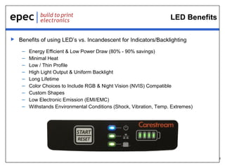
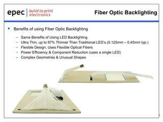
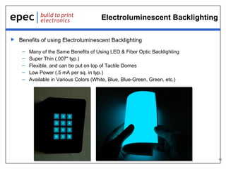
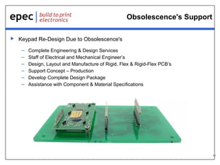
 DELIVERING QUALITY SINCE 1952.
Re-Designing Legacy
User Interfaces
21st Century Keypad
Technologies
08.15.14
2
Introduction
 This webinar will explain how Epec can provide Design & Engineering
support to bring your Legacy or obsolete keypad assembly into the 21st
century.
 During this presentation we will show possible design changes to User
Interface assemblies to include the following technologies:
– Rigid, Rigid-Flex and Flex Printed Circuit Card (PCB)
– LED, Fiber Optic and Electroluminescent Solutions
– Keypad Re-Design Due to Obsolescence's
3
Membrane Style Switch Explained
 Many Legacy keypads use a
flexible printed Membrane style
keypad assembly.
 This membrane keypad
assembly uses a silver epoxy
circuit layer that is screen
printed on two opposing
polyester sheets.
 The two printed layers are
stacked on top of each other to
form the switch circuit.
 The circuit is complete when the
two layers are pressed together.
4
Membrane Design Limitations
 Membrane designs have the following limitations:
– Material Selection Issues
• Incorrect material selection can cause premature failures of the assembly
– Electronic Component Mounting Issues
• Component failures can occur if assembly is deformed due to handling, environmental
conditions or sheer stress
– Component Real Estate Limitations
• Circuit trace layers and switch buttons consume most of the assembly leaving no room for
additional components
– High Density Connector Limitations
• Membrane assemblies connectors are limited to a 1.0 mm pitch minimum
5
Benefits of Using a Rigid PCB
 Benefits of using a Rigid PCB Assembly vs. Membrane Assembly
– Material Selection Issues
• Standard PCB materials and thicknesses can be used (0.010” and up)
– Electronic Component Mounting Issues
• Resilient to environmental conditions
• Self supporting by design and do not require a supporting backplate
– Component Real Estate Limitations
• Components can be soldered directly to the PCB
• Additional components can be added to the rear side of the PCB
– High Density Connector Limitations
• Connectors can be soldered directly to the PCB
• PCB can use high density connectors in various configurations (Thru-hole, locking, etc.)
6
Rigid PCB Additional Benefits
 Additional benefits of using a PCB Assembly vs. Membrane Assembly
– Higher Reliable Product
– Harsh Environment Use
– Use of Higher Quality Components and Materials
– Can Meet Overall Material Stack Ups Required
– Self Supporting, Metal Back Plate Not Required
– Reduced NRE & Tooling Costs
7
Flex & Rigid-Flex PCB Benefits
 Benefits of Flex & Rigid Flex vs. Rigid PCB’s
– All The Same Benefits as a Rigid PCB Design
– Unlimited Freedom of Packaging Geometry While Retaining the Precision Density
and Repeatability of Printed Circuits
– High Reliability Replacement for Wire and Cable Harness Assemblies
– Ability of Design to Fit to Your Device
8
LED Benefits
 Benefits of using LED’s vs. Incandescent for Indicators/Backlighting
– Energy Efficient & Low Power Draw (80% - 90% savings)
– Minimal Heat
– Low / Thin Profile
– High Light Output & Uniform Backlight
– Long Lifetime
– Color Choices to Include RGB & Night Vision (NVIS) Compatible
– Custom Shapes
– Low Electronic Emission (EMI/EMC)
– Withstands Environmental Conditions (Shock, Vibration, Temp. Extremes)
9
Fiber Optic Backlighting
 Benefits of using Fiber Optic Backlighting
– Same Benefits of Using LED Backlighting
– Ultra Thin, up to 97% Thinner Than Traditional LED’s (0.125mm – 0.45mm typ.)
– Flexible Design, Uses Flexible Optical Fibers
– Power Efficiency & Component Reduction (uses a single LED)
– Complex Geometries & Unusual Shapes
10
Electroluminescent Backlighting
 Benefits of using Electroluminescent Backlighting
– Many of the Same Benefits of Using LED & Fiber Optic Backlighting
– Super Thin (.007" typ.)
– Flexible, and can be put on top of Tactile Domes
– Low Power (.5 mA per sq. in typ.)
– Available in Various Colors (White, Blue, Blue-Green, Green, etc.)
11
Obsolescence's Support
 Keypad Re-Design Due to Obsolescence's
– Complete Engineering & Design Services
– Staff of Electrical and Mechanical Engineer’s
– Design, Layout and Manufacture of Rigid, Flex & Rigid-Flex PCB’s
– Support Concept – Production
– Develop Complete Design Package
– Assistance with Component & Material Specifications
12
Case Study
 Customer Requirements
– Re-design Product
– Conceptual Design, Minimal Design Drawings
– Small Form Factor
• Keypad required to fit in a 0.45” deep pocket
– IP68 - Ingress Protection
– Higher Reliable Product
• Current Keypad life cycle is 8-12 months
• Uses Membrane Style Switch
– High Density Mating Connector
• Mate with 0.5mm pitch ZIF connector
13
Case Study – cont.
 Value Add Design Services
– Conceptual Design, Minimal Design Drawings
• Developed Complete Design Package
• Product Renderings to Assist Customer Marketing
– Small Form Factor
• Design Flex PCB to meet Stack-up Tolerance
– IP68 - Ingress Protection
• Specify Design Features & Materials
– Higher Reliable Product
• Use of Flex PCB over Membrane Style
• Design Flex PCB with Gold Switch Contacts
– High Density Mating Connector
• Design Flex PCB with High Density Pigtail
14
Summary
 Epec can support you with your Design Phase.
 Epec can support Concept – Production
 Epec can also assist with the update of Legacy User Interfaces, to
include the following:
– Membrane to Printed Circuit Card Assembly
– Update to Rigid, Rigid-Flex and Flex Printed Circuit Card (PCB)
– Update to LED, Fiber Optic and Electroluminescent Solutions
– Support Keypad Re-Design issues due to Obsolescence's
15
Our Products
Battery Packs Flex & Rigid-Flex PCB’s User Interfaces
Fans & Motors Cable Assemblies Printed Circuit Boards
16
Design Centers & Technical Support
 Battery Pack & Power Management – Denver, CO
 User Interfaces – Largo, FL
 Fans & Motors – Wales, UK
 PCB’s – New Bedford, MA & Shenzhen, China
 Flex & Rigid Flex – Toronto, Canada
 Cable Assemblies – New Bedford, MA
 Our Engineering and Design teams are ready to help
our customers create world class and cost effective
product solutions.
17
Q&A
 Questions?
– Enter any questions you may have
in the Control Panel.
– If we don’t have time to get to it, we
will reply via email.
18
Thank You
Check out our previous webinars at www.epectec.com.
For more information email sales@epectec.com.
Stay Connected with Epec Engineered Technologies
Follow us on our social media sites for continuous technical updates and information:

Re-Designing Legacy User Interfaces with 21st Century Keypad Technologies

  • 1.
     DELIVERING QUALITYSINCE 1952. Re-Designing Legacy User Interfaces 21st Century Keypad Technologies 08.15.14
  • 2.
    2 Introduction  This webinarwill explain how Epec can provide Design & Engineering support to bring your Legacy or obsolete keypad assembly into the 21st century.  During this presentation we will show possible design changes to User Interface assemblies to include the following technologies: – Rigid, Rigid-Flex and Flex Printed Circuit Card (PCB) – LED, Fiber Optic and Electroluminescent Solutions – Keypad Re-Design Due to Obsolescence's
  • 3.
    3 Membrane Style SwitchExplained  Many Legacy keypads use a flexible printed Membrane style keypad assembly.  This membrane keypad assembly uses a silver epoxy circuit layer that is screen printed on two opposing polyester sheets.  The two printed layers are stacked on top of each other to form the switch circuit.  The circuit is complete when the two layers are pressed together.
  • 4.
    4 Membrane Design Limitations Membrane designs have the following limitations: – Material Selection Issues • Incorrect material selection can cause premature failures of the assembly – Electronic Component Mounting Issues • Component failures can occur if assembly is deformed due to handling, environmental conditions or sheer stress – Component Real Estate Limitations • Circuit trace layers and switch buttons consume most of the assembly leaving no room for additional components – High Density Connector Limitations • Membrane assemblies connectors are limited to a 1.0 mm pitch minimum
  • 5.
    5 Benefits of Usinga Rigid PCB  Benefits of using a Rigid PCB Assembly vs. Membrane Assembly – Material Selection Issues • Standard PCB materials and thicknesses can be used (0.010” and up) – Electronic Component Mounting Issues • Resilient to environmental conditions • Self supporting by design and do not require a supporting backplate – Component Real Estate Limitations • Components can be soldered directly to the PCB • Additional components can be added to the rear side of the PCB – High Density Connector Limitations • Connectors can be soldered directly to the PCB • PCB can use high density connectors in various configurations (Thru-hole, locking, etc.)
  • 6.
    6 Rigid PCB AdditionalBenefits  Additional benefits of using a PCB Assembly vs. Membrane Assembly – Higher Reliable Product – Harsh Environment Use – Use of Higher Quality Components and Materials – Can Meet Overall Material Stack Ups Required – Self Supporting, Metal Back Plate Not Required – Reduced NRE & Tooling Costs
  • 7.
    7 Flex & Rigid-FlexPCB Benefits  Benefits of Flex & Rigid Flex vs. Rigid PCB’s – All The Same Benefits as a Rigid PCB Design – Unlimited Freedom of Packaging Geometry While Retaining the Precision Density and Repeatability of Printed Circuits – High Reliability Replacement for Wire and Cable Harness Assemblies – Ability of Design to Fit to Your Device
  • 8.
    8 LED Benefits  Benefitsof using LED’s vs. Incandescent for Indicators/Backlighting – Energy Efficient & Low Power Draw (80% - 90% savings) – Minimal Heat – Low / Thin Profile – High Light Output & Uniform Backlight – Long Lifetime – Color Choices to Include RGB & Night Vision (NVIS) Compatible – Custom Shapes – Low Electronic Emission (EMI/EMC) – Withstands Environmental Conditions (Shock, Vibration, Temp. Extremes)
  • 9.
    9 Fiber Optic Backlighting Benefits of using Fiber Optic Backlighting – Same Benefits of Using LED Backlighting – Ultra Thin, up to 97% Thinner Than Traditional LED’s (0.125mm – 0.45mm typ.) – Flexible Design, Uses Flexible Optical Fibers – Power Efficiency & Component Reduction (uses a single LED) – Complex Geometries & Unusual Shapes
  • 10.
    10 Electroluminescent Backlighting  Benefitsof using Electroluminescent Backlighting – Many of the Same Benefits of Using LED & Fiber Optic Backlighting – Super Thin (.007" typ.) – Flexible, and can be put on top of Tactile Domes – Low Power (.5 mA per sq. in typ.) – Available in Various Colors (White, Blue, Blue-Green, Green, etc.)
  • 11.
    11 Obsolescence's Support  KeypadRe-Design Due to Obsolescence's – Complete Engineering & Design Services – Staff of Electrical and Mechanical Engineer’s – Design, Layout and Manufacture of Rigid, Flex & Rigid-Flex PCB’s – Support Concept – Production – Develop Complete Design Package – Assistance with Component & Material Specifications
  • 12.
    12 Case Study  CustomerRequirements – Re-design Product – Conceptual Design, Minimal Design Drawings – Small Form Factor • Keypad required to fit in a 0.45” deep pocket – IP68 - Ingress Protection – Higher Reliable Product • Current Keypad life cycle is 8-12 months • Uses Membrane Style Switch – High Density Mating Connector • Mate with 0.5mm pitch ZIF connector
  • 13.
    13 Case Study –cont.  Value Add Design Services – Conceptual Design, Minimal Design Drawings • Developed Complete Design Package • Product Renderings to Assist Customer Marketing – Small Form Factor • Design Flex PCB to meet Stack-up Tolerance – IP68 - Ingress Protection • Specify Design Features & Materials – Higher Reliable Product • Use of Flex PCB over Membrane Style • Design Flex PCB with Gold Switch Contacts – High Density Mating Connector • Design Flex PCB with High Density Pigtail
  • 14.
    14 Summary  Epec cansupport you with your Design Phase.  Epec can support Concept – Production  Epec can also assist with the update of Legacy User Interfaces, to include the following: – Membrane to Printed Circuit Card Assembly – Update to Rigid, Rigid-Flex and Flex Printed Circuit Card (PCB) – Update to LED, Fiber Optic and Electroluminescent Solutions – Support Keypad Re-Design issues due to Obsolescence's
  • 15.
    15 Our Products Battery PacksFlex & Rigid-Flex PCB’s User Interfaces Fans & Motors Cable Assemblies Printed Circuit Boards
  • 16.
    16 Design Centers &Technical Support  Battery Pack & Power Management – Denver, CO  User Interfaces – Largo, FL  Fans & Motors – Wales, UK  PCB’s – New Bedford, MA & Shenzhen, China  Flex & Rigid Flex – Toronto, Canada  Cable Assemblies – New Bedford, MA  Our Engineering and Design teams are ready to help our customers create world class and cost effective product solutions.
  • 17.
    17 Q&A  Questions? – Enterany questions you may have in the Control Panel. – If we don’t have time to get to it, we will reply via email.
  • 18.
    18 Thank You Check outour previous webinars at www.epectec.com. For more information email sales@epectec.com. Stay Connected with Epec Engineered Technologies Follow us on our social media sites for continuous technical updates and information: