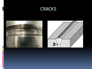
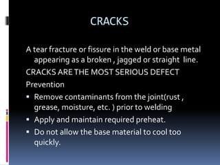
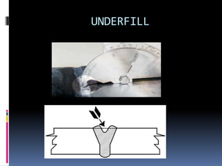
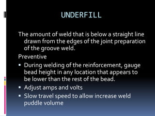
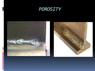
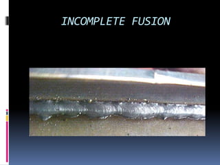
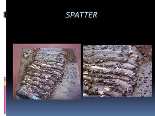
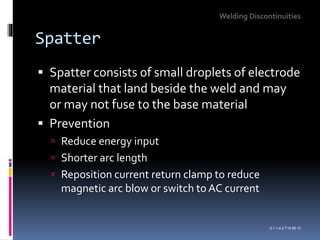
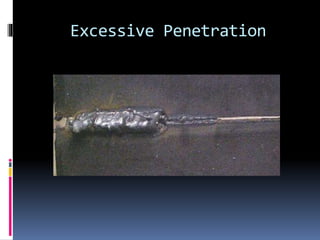
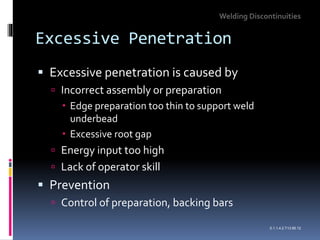
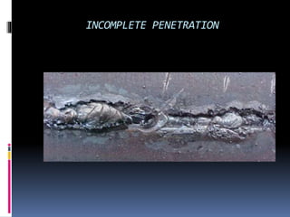
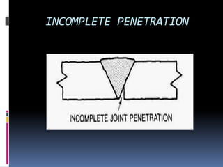
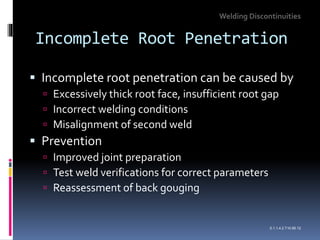
WELDING DEFECTS
WELDINGWORKSHOP PRACTICE
OBJECTIVE: Avoid and prevent
welding defects
Production without defects saves:
 WORK-TIME
 MATERIALS
 REPAIR COST
 DECREASE IN PRODUCTIVITY
HOW TO AVOID WELDING DEFECTS
 Avoidance of welding defects starts with correct
design and preparation.
 Use of recommended tools and fixtures should
be implemented with no excuses admitted for
temporary unavailability.
 Machine and tools are in good operating
condition , should be used with the correct
parameters ,according to approved procedure
 The welder or machine operator should be
proficient in the process selected.
WELD DEFECTS
 Welding-defects are excessive conditions,
outside the acceptance limits of deviations,
which risks to compromise the stability or the
functionality of the welded structure.
 They are also called rejectable
discontinuities.This means that the same
type of discontinuity of a lesser degree, might
be considered harmless and acceptable.
CRACKS
CRACKS
A tear fracture or fissure in the weld or base metal
appearing as a broken , jagged or straight line.
CRACKS ARETHE MOST SERIOUS DEFECT
Prevention
 Remove contaminants from the joint(rust ,
grease, moisture, etc. ) prior to welding
 Apply and maintain required preheat.
 Do not allow the base material to cool too
quickly.
UNDERFILL
UNDERFILL
The amount of weld that is below a straight line
drawn from the edges of the joint preparation
of the groove weld.
Preventive
 During welding of the reinforcement, gauge
bead height in any location that appears to
be lower than the rest of the bead.
 Adjust amps and volts
 Slow travel speed to allow increase weld
puddle volume
POROSITY
Porosity
 Porosity is the entrapment of small volumes
of gas in solidifying weld metal
 Prevention
 Drying consumables
 Cleaning, degreasing material being welded
 Electrode or filler metals with higher level of
deoxidants
 Sealing air leaks, reducing excess shielding gas
flow
Welding Discontinuities
0.1.1.4.2.T7.95.12
MINI–WELDING ROD OVEN
UNDERCUT
UNDERCUT
Undercut
A groove melted into the base metal and left unfilled by weld
metal.
Prevention
 Decrease amps/volts.
 Decrease travel speed.
 Maintain appropriate arc lenght.
 Adjust rod angle.
Welding Discontinuities
0.1.1.4.2.T12.95.12
OVERLAP
OVERLAP
Overlap
 Overlap is an imperfection at the weld toe or
root caused by metal flowing onto the
surface of the base metal without fusing to it
 Prevention
 Adjust electrode manipulation to ensure fusion of
base metal
 Limit size of fillet to 9-mm leg length
Welding Discontinuities
0.1.1.4.2.T11.95.12
INCOMPLETE FUSION
Lack of Fusion
 Lack of fusion is caused by incorrect welding
conditions
 Prevention
 Procedure for complete fusion should be verified
by testing
 Increased energy input
 Correct electrode angle and work position
Welding Discontinuities
0.1.1.4.2.T9.95.12
SPATTER
Spatter
 Spatter consists of small droplets of electrode
material that land beside the weld and may
or may not fuse to the base material
 Prevention
 Reduce energy input
 Shorter arc length
 Reposition current return clamp to reduce
magnetic arc blow or switch to AC current
Welding Discontinuities
0.1.1.4.2.T15.95.12
Excessive Penetration
 Excessive penetration is caused by
 Incorrect assembly or preparation
 Edge preparation too thin to support weld
underbead
 Excessive root gap
 Energy input too high
 Lack of operator skill
 Prevention
 Control of preparation, backing bars
Welding Discontinuities
0.1.1.4.2.T13.95.12
INCOMPLETE PENETRATION
Incomplete Root Penetration
 Incomplete root penetration can be caused by
 Excessively thick root face, insufficient root gap
 Incorrect welding conditions
 Misalignment of second weld
 Prevention
 Improved joint preparation
 Test weld verifications for correct parameters
 Reassessment of back gouging
Welding Discontinuities
0.1.1.4.2.T10.95.12
CONCAVE FILLET WELD
CONCAVE FILLET WELD
Fillet weld that sinks in the center.
Preventive
 Adjust amps and volts
 Decrease travel speed
 Maintain appropriate arc length/ wire stick
out
 Adjust torch and rod angle.
CONVEX FILLET WELD
CONVEX FILLET WELD
 A fillet weld that bulges out in the center.
Preventive
 Adjust amps/volts.
 Increase travel speed.
 Maintain proper wire stickout.
OFFSET
OFFSET
 A situation where base materials creating a
butt or corner joint have move out off
alignments. Offset is one of the major causes
of in services failures.
Preventive
 Ensure installing trade provides proper fit-up
prior to welding.
 Use approved temporary attachments (
strong back,flatbar, etc.) as needed to reduce
distortion.
SLAG INCLUSION
Slag inclusions
 Slag inclusions are irregularly shaped, not
spherical like porosity
 Prevention
 Position work and/or change electrode/flux to
increase slag control
 Better slag removal between passes
 Dress weld surface smooth if it is likely to cause
slag traps
 Remove heavy mill scale on plate
Welding Discontinuities
0.1.1.4.2.T8.95.12
ARC STRIKES
ARC STRIKES
 A discontinuity consisting of any localized
remelted metal, heat effected metal, or
change in surface profile of a finished weld or
base material surface resulting from an
electrical arc.
Preventive
 Prior to energizing welding equipment,
replace damaged welding lines and ground
cables.
THANK YOU FOR LISTENING!
INSTRUCTOR JonardA. Almuestro

WELD DEFECTS FOR VISUAL INSPECTION.pptx

  • 1.
  • 2.
    OBJECTIVE: Avoid andprevent welding defects Production without defects saves:  WORK-TIME  MATERIALS  REPAIR COST  DECREASE IN PRODUCTIVITY
  • 3.
    HOW TO AVOIDWELDING DEFECTS  Avoidance of welding defects starts with correct design and preparation.  Use of recommended tools and fixtures should be implemented with no excuses admitted for temporary unavailability.  Machine and tools are in good operating condition , should be used with the correct parameters ,according to approved procedure  The welder or machine operator should be proficient in the process selected.
  • 4.
    WELD DEFECTS  Welding-defectsare excessive conditions, outside the acceptance limits of deviations, which risks to compromise the stability or the functionality of the welded structure.  They are also called rejectable discontinuities.This means that the same type of discontinuity of a lesser degree, might be considered harmless and acceptable.
  • 5.
  • 6.
    CRACKS A tear fractureor fissure in the weld or base metal appearing as a broken , jagged or straight line. CRACKS ARETHE MOST SERIOUS DEFECT Prevention  Remove contaminants from the joint(rust , grease, moisture, etc. ) prior to welding  Apply and maintain required preheat.  Do not allow the base material to cool too quickly.
  • 7.
  • 8.
    UNDERFILL The amount ofweld that is below a straight line drawn from the edges of the joint preparation of the groove weld. Preventive  During welding of the reinforcement, gauge bead height in any location that appears to be lower than the rest of the bead.  Adjust amps and volts  Slow travel speed to allow increase weld puddle volume
  • 9.
  • 10.
    Porosity  Porosity isthe entrapment of small volumes of gas in solidifying weld metal  Prevention  Drying consumables  Cleaning, degreasing material being welded  Electrode or filler metals with higher level of deoxidants  Sealing air leaks, reducing excess shielding gas flow Welding Discontinuities 0.1.1.4.2.T7.95.12
  • 11.
  • 12.
  • 13.
  • 14.
    Undercut A groove meltedinto the base metal and left unfilled by weld metal. Prevention  Decrease amps/volts.  Decrease travel speed.  Maintain appropriate arc lenght.  Adjust rod angle. Welding Discontinuities 0.1.1.4.2.T12.95.12
  • 15.
  • 16.
  • 17.
    Overlap  Overlap isan imperfection at the weld toe or root caused by metal flowing onto the surface of the base metal without fusing to it  Prevention  Adjust electrode manipulation to ensure fusion of base metal  Limit size of fillet to 9-mm leg length Welding Discontinuities 0.1.1.4.2.T11.95.12
  • 18.
  • 19.
    Lack of Fusion Lack of fusion is caused by incorrect welding conditions  Prevention  Procedure for complete fusion should be verified by testing  Increased energy input  Correct electrode angle and work position Welding Discontinuities 0.1.1.4.2.T9.95.12
  • 20.
  • 21.
    Spatter  Spatter consistsof small droplets of electrode material that land beside the weld and may or may not fuse to the base material  Prevention  Reduce energy input  Shorter arc length  Reposition current return clamp to reduce magnetic arc blow or switch to AC current Welding Discontinuities 0.1.1.4.2.T15.95.12
  • 22.
  • 23.
    Excessive Penetration  Excessivepenetration is caused by  Incorrect assembly or preparation  Edge preparation too thin to support weld underbead  Excessive root gap  Energy input too high  Lack of operator skill  Prevention  Control of preparation, backing bars Welding Discontinuities 0.1.1.4.2.T13.95.12
  • 24.
  • 25.
  • 26.
    Incomplete Root Penetration Incomplete root penetration can be caused by  Excessively thick root face, insufficient root gap  Incorrect welding conditions  Misalignment of second weld  Prevention  Improved joint preparation  Test weld verifications for correct parameters  Reassessment of back gouging Welding Discontinuities 0.1.1.4.2.T10.95.12
  • 27.
  • 28.
    CONCAVE FILLET WELD Filletweld that sinks in the center. Preventive  Adjust amps and volts  Decrease travel speed  Maintain appropriate arc length/ wire stick out  Adjust torch and rod angle.
  • 29.
  • 30.
    CONVEX FILLET WELD A fillet weld that bulges out in the center. Preventive  Adjust amps/volts.  Increase travel speed.  Maintain proper wire stickout.
  • 31.
  • 32.
    OFFSET  A situationwhere base materials creating a butt or corner joint have move out off alignments. Offset is one of the major causes of in services failures. Preventive  Ensure installing trade provides proper fit-up prior to welding.  Use approved temporary attachments ( strong back,flatbar, etc.) as needed to reduce distortion.
  • 33.
  • 34.
    Slag inclusions  Slaginclusions are irregularly shaped, not spherical like porosity  Prevention  Position work and/or change electrode/flux to increase slag control  Better slag removal between passes  Dress weld surface smooth if it is likely to cause slag traps  Remove heavy mill scale on plate Welding Discontinuities 0.1.1.4.2.T8.95.12
  • 35.
  • 36.
    ARC STRIKES  Adiscontinuity consisting of any localized remelted metal, heat effected metal, or change in surface profile of a finished weld or base material surface resulting from an electrical arc. Preventive  Prior to energizing welding equipment, replace damaged welding lines and ground cables.
  • 37.
    THANK YOU FORLISTENING! INSTRUCTOR JonardA. Almuestro

Editor's Notes

  • #11 Molten weld metal is able to hold more gas than solid weld metal. For this reason, gas bubbles tend to evolve as the liquid metal solidifies. These gas bubbles trapped within the solid weld metal are referred to as porosity. Although porosity is sometimes noted at the surface of a weld, visual inspection cannot detect internal porosity. Radiography and ultrasonic methods are required. Localized regions of porosity can be cut from a weld; a repair is then made. For general porosity throughout a weld, the entire weld must be gouged out and rewelded.
  • #15 Undercut is another defect that can be associated with horizontal welding among other factors such as high current and excessive weaving. Flat position welding can aid in eliminating this discontinuity. It is detected visually and measured by a depth gauge. Deep undercut is ground out and weld repaired.
  • #18 Overlap is often associated with horizontal welding; welding in the flat position can help to eliminate this problem. Overlap can be detected visually and can be supplemented with dye penetrant. It is corrected by cutting back to sound weld metal. Rewelding may be necessary.
  • #20 Lack of fusion can occur at the weld sidewall, root, or between individual passes. Magnetic particle and dye or fluorescent penetrant may be used to detect this discontinuity if it reaches the surface. Otherwise, radiography or ultrasonic methods must be used. Affected regions must be cut out and rewelded.
  • #22 As metal drops transfer from the electrode to the weld pool, some are blown clear of the weld and form drops of spatter on the base plate. All open arc consumable electrode processes produce some spatter. Spatter can occur when the energy input is too high or when the arc length is excessive. Arc blow can also cause spatter, as can insufficient inductance in GMAW or CO2 welding. Spatter can be detected visually. It can be removed by scraping or by light grinding. Anti-spatter coatings are available on the market that prevent spatter from adhering to the base material.
  • #24 Maintaining uniform root penetration requires great skill on the part of the welder, especially when welding butted pipe ends. Excessive root penetration is detected visually; however in the case of pipelines, radiography is used if the pipe bore cannot be examined. Excessive penetration is corrected by such dressing operations as grinding. In piping, it is corrected by broaching.
  • #27 Incomplete root penetration is the failure of a weld to extend into the root of a joint. For a double weld, it is an internal discontinuity and can be detected only by radiography or ultrasonic testing. It can be detected by magnetic particle, and dye or fluorescent penetrant methods if the root side is accessible. A long pipeline would be an example of when the weld root (inside the pipe) would not be accessible. This defect is repaired by cutting it out and rewelding.
  • #35 Slag inclusions, as the name implies, are small pieces of welding slag which are trapped in the weld metal. Unlike porosity, which is usually spherical, slag inclusions are irregularly shaped. Since these are internal discontinuities, radiography or ultrasonic testing is required for detection. Weld regions containing slag inclusions must be cut out and rewelded.