Downloaded 908 times

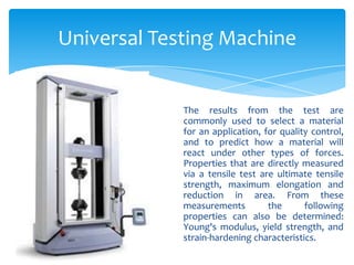
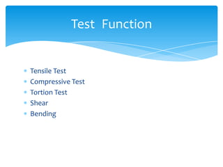
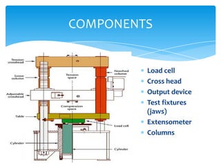
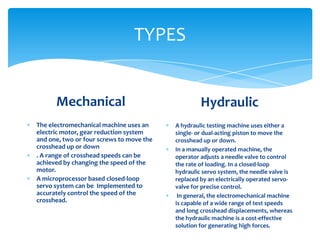
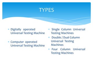
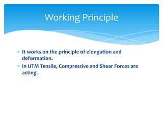
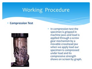

The document discusses a presentation on a universal testing machine. It describes how the machine is used to apply tensile, compressive, and shear forces to test materials and measure their properties. It explains that the machine uses load cells, crossheads, and columns to grip specimens and apply and measure forces. The document outlines the working principle of the machine and procedures for tensile and compression tests.