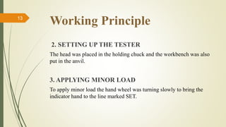
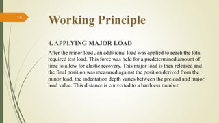
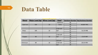
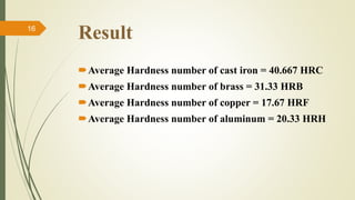
Presentation on
ROCKWELL HARDNESS TEST
Presented By
Kazi Noor-E-Asfia (148015)
Miraz Hossain Akash (148016)
Afrin Sadia (148017)
Abu Bakar Siddique (148018)
Prangon Das (148019)
Aparajita Talukder (148020)
Department of Mechatronics Engineering,
Rajshahi University of Engineering & Technology
Contents
 Objectives
 Required apparatus
 Theory
 Figure of the machine
 Working principle
 Data table
 Result
 Discussion and conclusion
2
Objectives
To determine the Rockwell hardness number of
various metal specimens.
To develop an understanding of suitable scales for
hardness test specimens.
3
Required Apparatus
10 Kg Rockwell Hardness Tester Machine
Cast iron material
Brass
Copper
Aluminum
Diamond cone head
1/16 inch ball head.
4
Why name ROCKWELL HARDNESS?
On February 11, 1919, Hugh Rockwell and Stanly
Rockwell received a patent for the Rockwell hardness
tester.
A device for measuring the resistance of metallic materials
to force.
5
Theory
Hardness is defined as the resistance of a metal to
permanent deformation of it’s surface.
This deformation may be in the form of scratching,
indentation or cutting.
Sometimes there is a direct connection between the
hardness and few other mechanical properties.
So, by knowing the hardness number we can find out the
tensile strength of the specimen
6
In This Experiment
In this experiment we measured the average hardness
number of the following materials :
Cast Iron.
Brass
Copper &
Aluminum
7
Figure8
Theory
In both figure the ball having a diameter of ‘d’ in the indenter,
which is pressed against a piece of metal.
For the same load P, the indentations will be different for the
soft and hard materials.
For the above two cases h2<h1, i.e., mat.2 is harder than mat.1.
Indentation depends upon load(P) indenter diameter(d) time
during which load is applied(t) and the hardness of the
material(H).
If P, d & t are kept constant then it is a function of hardness
only.
9
Rockwell Hardness Tester10
The tester is composed of
(i) machine body,
(ii)Penetrator,
(iii)loading and unloading mechanism,
(iv)measurement mechanism,
(v)load changeover mechanism,
(vi)specimen support mechanism and so
on.
Description11
 The machine body is the shell of the tester, where other parts are fitted directly
or indirectly onto the machine body.
 The total test force is composed of main test force plus preliminary test force which is
produced by the weight of parts including larger lever and main shaft.
 The top end-face of penetrator bears the total test force and the sharp tip penetrates into
the surface of the object to be tested.
 The load changeover handle regulates the positions of weight changeover support
bracket resulting in different composition of weights.
 The loading handle is to apply main test force.
 The unloading handle can be pushed back to remove the main test force.
 Test value can be read directly from the indication dial gauge.
 The specimen support mechanism includes worktable, elevating screw and hand wheel
which is used for bearing hardness blocks and the parts to be tested.
Working Principle
1. SELECTING THE HEAD AND TEST BLOCK
Hardened steel and hard alloys like Cast Iron were tested in the
Rockwell C scale, using a diamond cone as head and a 150 kg major
load. Brass was tested in B scale, using a 1/16” ball as head and a 100
kg major load. Copper was tested in F scale, using a 1/16” ball as head
and 60 kg major load. Aluminum was tested in H scale. Using a 1/16”
ball as head and 60 kg major load.
12
Working Principle
2. SETTING UP THE TESTER
The head was placed in the holding chuck and the workbench was also
put in the anvil.
3. APPLYING MINOR LOAD
To apply minor load the hand wheel was turning slowly to bring the
indicator hand to the line marked SET.
13
Working Principle
4. APPLYING MAJOR LOAD
After the minor load , an additional load was applied to reach the total
required test load. This force was held for a predetermined amount of
time to allow for elastic recovery. This major load is then released and
the final position was measured against the position derived from the
minor load, the indentation depth varies between the preload and major
load value. This distance is converted to a hardness number.
14
Data Table15
Result
Average Hardness number of cast iron = 40.667 HRC
Average Hardness number of brass = 31.33 HRB
Average Hardness number of copper = 17.67 HRF
Average Hardness number of aluminum = 20.33 HRH
16
Discussion
An analog machine has it's drawbacks. Since the readings
were taken manually, accuracy wasn't ensured. The weigh
scale was positioned at a higher level unlike the dial gauge
which may have resulted in more errors. The 1/8inch ball
wasn't available so 1/16 inch ball was used instead. The
specimen were old and reused from time to time which
may result in slight changes of hardness property.
17
Conclusion
The Rockwell Hardness number of the given specimen cast
iron, brass, copper, aluminum were determined by this
experiment. The specimen were differentiated according to
their hardness scale obtained by the experiment. This scale is
a good parameter for material selection with suitable loading
for construction of different objects.
18
***THE END***
Thank You All
19

Rockwell hardness test

  • 1.
    Presentation on ROCKWELL HARDNESSTEST Presented By Kazi Noor-E-Asfia (148015) Miraz Hossain Akash (148016) Afrin Sadia (148017) Abu Bakar Siddique (148018) Prangon Das (148019) Aparajita Talukder (148020) Department of Mechatronics Engineering, Rajshahi University of Engineering & Technology
  • 2.
    Contents  Objectives  Requiredapparatus  Theory  Figure of the machine  Working principle  Data table  Result  Discussion and conclusion 2
  • 3.
    Objectives To determine theRockwell hardness number of various metal specimens. To develop an understanding of suitable scales for hardness test specimens. 3
  • 4.
    Required Apparatus 10 KgRockwell Hardness Tester Machine Cast iron material Brass Copper Aluminum Diamond cone head 1/16 inch ball head. 4
  • 5.
    Why name ROCKWELLHARDNESS? On February 11, 1919, Hugh Rockwell and Stanly Rockwell received a patent for the Rockwell hardness tester. A device for measuring the resistance of metallic materials to force. 5
  • 6.
    Theory Hardness is definedas the resistance of a metal to permanent deformation of it’s surface. This deformation may be in the form of scratching, indentation or cutting. Sometimes there is a direct connection between the hardness and few other mechanical properties. So, by knowing the hardness number we can find out the tensile strength of the specimen 6
  • 7.
    In This Experiment Inthis experiment we measured the average hardness number of the following materials : Cast Iron. Brass Copper & Aluminum 7
  • 8.
  • 9.
    Theory In both figurethe ball having a diameter of ‘d’ in the indenter, which is pressed against a piece of metal. For the same load P, the indentations will be different for the soft and hard materials. For the above two cases h2<h1, i.e., mat.2 is harder than mat.1. Indentation depends upon load(P) indenter diameter(d) time during which load is applied(t) and the hardness of the material(H). If P, d & t are kept constant then it is a function of hardness only. 9
  • 10.
    Rockwell Hardness Tester10 Thetester is composed of (i) machine body, (ii)Penetrator, (iii)loading and unloading mechanism, (iv)measurement mechanism, (v)load changeover mechanism, (vi)specimen support mechanism and so on.
  • 11.
    Description11  The machinebody is the shell of the tester, where other parts are fitted directly or indirectly onto the machine body.  The total test force is composed of main test force plus preliminary test force which is produced by the weight of parts including larger lever and main shaft.  The top end-face of penetrator bears the total test force and the sharp tip penetrates into the surface of the object to be tested.  The load changeover handle regulates the positions of weight changeover support bracket resulting in different composition of weights.  The loading handle is to apply main test force.  The unloading handle can be pushed back to remove the main test force.  Test value can be read directly from the indication dial gauge.  The specimen support mechanism includes worktable, elevating screw and hand wheel which is used for bearing hardness blocks and the parts to be tested.
  • 12.
    Working Principle 1. SELECTINGTHE HEAD AND TEST BLOCK Hardened steel and hard alloys like Cast Iron were tested in the Rockwell C scale, using a diamond cone as head and a 150 kg major load. Brass was tested in B scale, using a 1/16” ball as head and a 100 kg major load. Copper was tested in F scale, using a 1/16” ball as head and 60 kg major load. Aluminum was tested in H scale. Using a 1/16” ball as head and 60 kg major load. 12
  • 13.
    Working Principle 2. SETTINGUP THE TESTER The head was placed in the holding chuck and the workbench was also put in the anvil. 3. APPLYING MINOR LOAD To apply minor load the hand wheel was turning slowly to bring the indicator hand to the line marked SET. 13
  • 14.
    Working Principle 4. APPLYINGMAJOR LOAD After the minor load , an additional load was applied to reach the total required test load. This force was held for a predetermined amount of time to allow for elastic recovery. This major load is then released and the final position was measured against the position derived from the minor load, the indentation depth varies between the preload and major load value. This distance is converted to a hardness number. 14
  • 15.
  • 16.
    Result Average Hardness numberof cast iron = 40.667 HRC Average Hardness number of brass = 31.33 HRB Average Hardness number of copper = 17.67 HRF Average Hardness number of aluminum = 20.33 HRH 16
  • 17.
    Discussion An analog machinehas it's drawbacks. Since the readings were taken manually, accuracy wasn't ensured. The weigh scale was positioned at a higher level unlike the dial gauge which may have resulted in more errors. The 1/8inch ball wasn't available so 1/16 inch ball was used instead. The specimen were old and reused from time to time which may result in slight changes of hardness property. 17
  • 18.
    Conclusion The Rockwell Hardnessnumber of the given specimen cast iron, brass, copper, aluminum were determined by this experiment. The specimen were differentiated according to their hardness scale obtained by the experiment. This scale is a good parameter for material selection with suitable loading for construction of different objects. 18
  • 19.