Downloaded 1,252 times

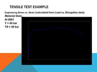
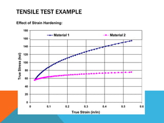
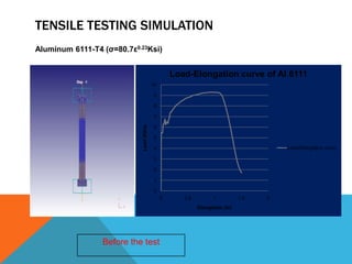
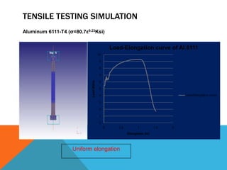
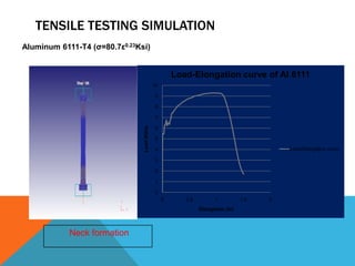

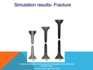

The document discusses tensile testing procedures and principles. It outlines the components of a universal testing machine used for tensile testing, including the load frame, load cell, crosshead, and output devices. It then provides details on conducting a tensile test, including specimen preparation, loading procedure, and data collection. Examples are given demonstrating how load and elongation data can be used to determine material properties and how finite element analysis can simulate the effects of strain hardening.