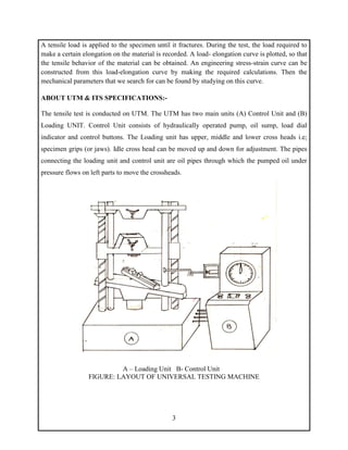
1
D.Y. PATIL COLLEGE OF ENGINEERING
AKURDI, PUNE-411044
Department of Mechanical Engineering
SOLID MECHANICS [202042]
SE MECH [2019 PAT]
TENSION TEST ON DUCTILE
MATERIAL
2
Experiment No :
Title : Tension Test on given specimen
Date of Performance :
Date of Checking :
AIM: - To Perform tensile test on a ___________________specimen
OBJECTIVE: -
1. Students are required to understand the principle of a uniaxial tensile testing and gain
their practices on operating the tensile testing machine to achieve the required tensile
properties.
2. Students are able to explain load-extension and stress-strain relationships and represent
them in graphical forms.
3. To evaluate the values of ultimate tensile strength, yield strength, % elongation, fracture
strain and Young's Modulus of the selected metals when subjected to uniaxial tensile
loading.
4. Students can explain deformation and fracture characteristics of different materials such
as aluminium, steels or brass when subjected to uniaxial tensile loading.
APPARATUS: -
(i) Universal Testing Machine (UTM) (ii) specimens
(iii) Graph paper (iv) Scale
(v) Vernier Caliper (vi) Extensometer
THEORY: -
Mechanical testing plays an important role in evaluating fundamental properties of engineering
materials as well as in developing new materials and in controlling the quality of materials for
use in design and construction. If a material is to be used as part of an engineering structure that
will be subjected to a load, it is important to know that the material is strong enough and rigid
enough to withstand the loads that it will experience in service. As a result engineers have
developed a number of experimental techniques for mechanical testing of engineering materials
subjected to tension, compression, bending or torsion loading. The most common type of test
used to measure the mechanical properties of a material is the Tension Test. Tension test is
widely used to provide basic design information on the strength of materials and is an acceptance
test for the specification of materials. The major parameters that describe the stress-strain curve
obtained during the tension test are the tensile strength (UTS), yield strength or yield point (σy),
elastic modulus (E), percent elongation (∆L%) and the reduction in area (RA%). Toughness,
Resilience, Poisson’s ratio (ν) can also be found by the use of this testing technique.
3
A tensile load is applied to the specimen until it fractures. During the test, the load required to
make a certain elongation on the material is recorded. A load- elongation curve is plotted, so that
the tensile behavior of the material can be obtained. An engineering stress-strain curve can be
constructed from this load-elongation curve by making the required calculations. Then the
mechanical parameters that we search for can be found by studying on this curve.
ABOUT UTM & ITS SPECIFICATIONS:-
The tensile test is conducted on UTM. The UTM has two main units (A) Control Unit and (B)
Loading UNIT. Control Unit consists of hydraulically operated pump, oil sump, load dial
indicator and control buttons. The Loading unit has upper, middle and lower cross heads i.e;
specimen grips (or jaws). Idle cross head can be moved up and down for adjustment. The pipes
connecting the loading unit and control unit are oil pipes through which the pumped oil under
pressure flows on left parts to move the crossheads.
A – Loading Unit B- Control Unit
FIGURE: LAYOUT OF UNIVERSAL TESTING MACHINE
4
SPECIFICATIONS:-
1. Load capacity = _____ Ton
2. Least count = ______ Kg
3. Power supply = 440V
FIGURE: UNIVERSAL TESTING MACHINE
5
PROCEDURE:-
1. Measure the original length and diameter of the specimen. The length may either be
length of gauge section which is marked on the specimen with a preset punch of the total
length of the specimen.
2. Insert the specimen into grips of the test machine and attach strain-measuring device to it.
3. Begin the load application and record load versus elongation data.
4. Take readings more frequently as yield point is approached.
5. Measure elongation values with the help of dividers and a ruler.
6. Continue the test till Fracture occurs.
7. By joining the two broken halves of the specimen together, measure the final length and
diameter of specimen.
OBESERVATION:- Material: ____________________
A) Original dimensions
Length between ___Markings = ______mm
Diameter = ______________________ mm
Area = _________________________mm2
B) Final Dimensions:
Length between ___Markings = ______mm
Diameter = ______________________ mm
Area = _________________________mm2
Least count of extensometer: _________
Extensometer Used to Measure Deflection during Tensile Load
6
OBSERVATION TABLE:-
Load in KN Extensometer Reading Ivory Scale Reading
A B Average
7
GRAPH 1:- ______________________Vs_____________________
8
GRAPH 2:- ______________________Vs_____________________
9
Sample Calculations:-
A. Yield Stress =
Yield Load
Original C/S Area
=
B. Ultimate TensileStrength =
Maximum tensile load
Original C/S Area
C. Young’sModulus E = Slope ∗ (𝟏/𝟎. 𝟎𝟏) ∗ L/A = ___________GPa
[Note: Here Length of the specimen between the grips (End Markings on Specimen)
=______mm]
D. Percentage Elongation =
Final length (at fracture) – original length
Original length
=
E. Percentage Reduction in area =
Original area – Area at fracture
Original area
=
10
SUMMARY OF RESULTS:-
Result Actual Value Calculated Value Percentage Error
Yield Stress (N/mm2
)
Ultimate Tensile Strength
(N/mm2
)
Modulus of Elasticity (GPa)
Percentage Elongation (%)
Percentage Reduction In
Area (%)
PRECAUTION:-
1. The specimen should be prepared in proper dimensions.
2. The specimen should be properly adjusted to get between the jaws.
3. Take reading carefully.
4. If the strain measuring device is an extensometer it should be removed before necking
begins.
5. Measure deflection on scale accurately & carefully
6. After breaking specimen, stop the Machine.
CONCLUSION:-

1.SM_LAB_TENSION_TEST_MS.pdf

  • 1.
    1 D.Y. PATIL COLLEGEOF ENGINEERING AKURDI, PUNE-411044 Department of Mechanical Engineering SOLID MECHANICS [202042] SE MECH [2019 PAT] TENSION TEST ON DUCTILE MATERIAL
  • 2.
    2 Experiment No : Title: Tension Test on given specimen Date of Performance : Date of Checking : AIM: - To Perform tensile test on a ___________________specimen OBJECTIVE: - 1. Students are required to understand the principle of a uniaxial tensile testing and gain their practices on operating the tensile testing machine to achieve the required tensile properties. 2. Students are able to explain load-extension and stress-strain relationships and represent them in graphical forms. 3. To evaluate the values of ultimate tensile strength, yield strength, % elongation, fracture strain and Young's Modulus of the selected metals when subjected to uniaxial tensile loading. 4. Students can explain deformation and fracture characteristics of different materials such as aluminium, steels or brass when subjected to uniaxial tensile loading. APPARATUS: - (i) Universal Testing Machine (UTM) (ii) specimens (iii) Graph paper (iv) Scale (v) Vernier Caliper (vi) Extensometer THEORY: - Mechanical testing plays an important role in evaluating fundamental properties of engineering materials as well as in developing new materials and in controlling the quality of materials for use in design and construction. If a material is to be used as part of an engineering structure that will be subjected to a load, it is important to know that the material is strong enough and rigid enough to withstand the loads that it will experience in service. As a result engineers have developed a number of experimental techniques for mechanical testing of engineering materials subjected to tension, compression, bending or torsion loading. The most common type of test used to measure the mechanical properties of a material is the Tension Test. Tension test is widely used to provide basic design information on the strength of materials and is an acceptance test for the specification of materials. The major parameters that describe the stress-strain curve obtained during the tension test are the tensile strength (UTS), yield strength or yield point (σy), elastic modulus (E), percent elongation (∆L%) and the reduction in area (RA%). Toughness, Resilience, Poisson’s ratio (ν) can also be found by the use of this testing technique.
  • 3.
    3 A tensile loadis applied to the specimen until it fractures. During the test, the load required to make a certain elongation on the material is recorded. A load- elongation curve is plotted, so that the tensile behavior of the material can be obtained. An engineering stress-strain curve can be constructed from this load-elongation curve by making the required calculations. Then the mechanical parameters that we search for can be found by studying on this curve. ABOUT UTM & ITS SPECIFICATIONS:- The tensile test is conducted on UTM. The UTM has two main units (A) Control Unit and (B) Loading UNIT. Control Unit consists of hydraulically operated pump, oil sump, load dial indicator and control buttons. The Loading unit has upper, middle and lower cross heads i.e; specimen grips (or jaws). Idle cross head can be moved up and down for adjustment. The pipes connecting the loading unit and control unit are oil pipes through which the pumped oil under pressure flows on left parts to move the crossheads. A – Loading Unit B- Control Unit FIGURE: LAYOUT OF UNIVERSAL TESTING MACHINE
  • 4.
    4 SPECIFICATIONS:- 1. Load capacity= _____ Ton 2. Least count = ______ Kg 3. Power supply = 440V FIGURE: UNIVERSAL TESTING MACHINE
  • 5.
    5 PROCEDURE:- 1. Measure theoriginal length and diameter of the specimen. The length may either be length of gauge section which is marked on the specimen with a preset punch of the total length of the specimen. 2. Insert the specimen into grips of the test machine and attach strain-measuring device to it. 3. Begin the load application and record load versus elongation data. 4. Take readings more frequently as yield point is approached. 5. Measure elongation values with the help of dividers and a ruler. 6. Continue the test till Fracture occurs. 7. By joining the two broken halves of the specimen together, measure the final length and diameter of specimen. OBESERVATION:- Material: ____________________ A) Original dimensions Length between ___Markings = ______mm Diameter = ______________________ mm Area = _________________________mm2 B) Final Dimensions: Length between ___Markings = ______mm Diameter = ______________________ mm Area = _________________________mm2 Least count of extensometer: _________ Extensometer Used to Measure Deflection during Tensile Load
  • 6.
    6 OBSERVATION TABLE:- Load inKN Extensometer Reading Ivory Scale Reading A B Average
  • 7.
  • 8.
  • 9.
    9 Sample Calculations:- A. YieldStress = Yield Load Original C/S Area = B. Ultimate TensileStrength = Maximum tensile load Original C/S Area C. Young’sModulus E = Slope ∗ (𝟏/𝟎. 𝟎𝟏) ∗ L/A = ___________GPa [Note: Here Length of the specimen between the grips (End Markings on Specimen) =______mm] D. Percentage Elongation = Final length (at fracture) – original length Original length = E. Percentage Reduction in area = Original area – Area at fracture Original area =
  • 10.
    10 SUMMARY OF RESULTS:- ResultActual Value Calculated Value Percentage Error Yield Stress (N/mm2 ) Ultimate Tensile Strength (N/mm2 ) Modulus of Elasticity (GPa) Percentage Elongation (%) Percentage Reduction In Area (%) PRECAUTION:- 1. The specimen should be prepared in proper dimensions. 2. The specimen should be properly adjusted to get between the jaws. 3. Take reading carefully. 4. If the strain measuring device is an extensometer it should be removed before necking begins. 5. Measure deflection on scale accurately & carefully 6. After breaking specimen, stop the Machine. CONCLUSION:-