Automation and Robotics Week 08 Theory Notes 20ME51I.pdf

Day 01 Session: Concepts of Industrial Robots, Applications of Robotics, Types of robots, Configurations of robots – Articulated Robot, Polar configuration, SCARA, Cartesian Co-ordinate Robot, Delta Robot, Key Components of Robot. Day 02 Session: Wrist configuration, Work Volume Degree of Freedom- Forward and Back, Up and Down, Left and Right, Pitch, Yaw, Roll, Joint Notation & Type of joints in robot- Linear Joint (L Joint), Orthogonal Joint (O Joint), Rotational Joint (R Joint), Twisting Joint (T Joint), Revolving Joint (V Joint) End Effectors- Grippers, Tools, Types of grippers, Factors to be considered for Selecting a Gripper, Robotic Drives- Electric Drive, Pneumatic Drive, Hydraulic Drive Day 03 Session: Robot Control systems- • Point- to Point control Systems • Continuous Path Control • Intelligent control • Controller Components • System Control Robotic Coordinate system using a robot • Joint co-ordinate system • Rectangular co-ordinate system • User or object coordinate system • Tool coordinate system. Steps to define user co-ordinate system. • Defining X, Y, Z co-ordinate system • Verifying co-ordinate system by multiple motion movements.

Recommended
Recommended
More Related Content
What's hot
What's hot (20)
Similar to Automation and Robotics Week 08 Theory Notes 20ME51I.pdf
Similar to Automation and Robotics Week 08 Theory Notes 20ME51I.pdf (20)
More from THANMAY JS
More from THANMAY JS (20)
Recently uploaded
Recently uploaded (20)
Automation and Robotics Week 08 Theory Notes 20ME51I.pdf
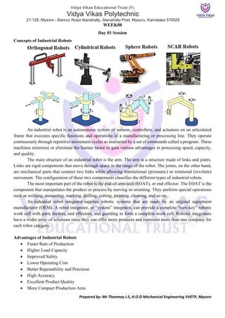
- 1. Vidya Vikas Educational Trust (R), Vidya Vikas Polytechnic 27-128, Mysore - Bannur Road Alanahally, Alanahally Post, Mysuru, Karnataka 570028 Prepared by: Mr Thanmay J.S, H.O.D Mechanical Engineering VVETP, Mysore WEEK08 Day 01 Session Concepts of Industrial Robots An industrial robot is an autonomous system of sensors, controllers, and actuators on an articulated frame that executes specific functions and operations in a manufacturing or processing line. They operate continuously through repetitive movement cycles as instructed by a set of commands called a program. These machines minimize or eliminate the human factor to gain various advantages in processing speed, capacity, and quality. The main structure of an industrial robot is the arm. The arm is a structure made of links and joints. Links are rigid components that move through space in the range of the robot. The joints, on the other hand, are mechanical parts that connect two links while allowing translational (prismatic) or rotational (revolute) movement. The configuration of these two components classifies the different types of industrial robots. The most important part of the robot is the end-of-arm-tool (EOAT), or end effector. The EOAT is the component that manipulates the product or process by moving or orienting. They perform special operations such as welding, measuring, marking, drilling, cutting, painting, cleaning, and so on. An industrial robot integrator supplies robotic systems that are made by an original equipment manufacturer (OEM). A robot integrator, or “system” integrator, can provide a complete “turn-key” robotic work cell with parts feeders, end effectors, and guarding to form a complete work cell. Robotic integrators have a wider array of solutions since they can offer more products and represent more than one company for each robot category. Advantages of Industrial Robots • Faster Rate of Production • Higher Load Capacity • Improved Safety • Lower Operating Cost • Better Repeatability and Precision • High Accuracy • Excellent Product Quality • More Compact Production Area
- 2. Vidya Vikas Educational Trust (R), Vidya Vikas Polytechnic 27-128, Mysore - Bannur Road Alanahally, Alanahally Post, Mysuru, Karnataka 570028 Prepared by: Mr Thanmay J.S, H.O.D Mechanical Engineering VVETP, Mysore Applications of Robotics a) Product Assembly: Industrial robots are widely used as assembly machines. They are suitable for highly repetitive but precise tasks that are tedious for a human operator. Their end effectors are usually mechanical grippers that pick, place, and orient small or large parts in quick succession. Sensors are optional and are typically used for recalibrating the accuracy of the robot ‘s movements. b) Non-Conventional Machining: Common non-conventional methods of machining include waterjet cutting, laser cutting, abrasive jet machining, electric discharge machining (EDM), and plasma cutting. These non-contact machining processes perform material removal by using highly concentrated streams of water, light, electric charge, or another physical entity. c) Palletizing and Depalletizing: Palletizing is the process of combining several individual products into a single load for more efficient product handling, storage, and distribution. On the other hand, depalletizing is the opposite: It is the disassembly of a palletized load. Both of these processes are labor-intensive and can quickly become process bottlenecks. Robotic palletizers are used for their better product handling and cost- efficiency. End effectors integrated into robotic palletizers are mechanical, pneumatic, and vacuum grippers that operate by picking, orienting, and stacking items, similar to the operation of assembly machines. d) Welding: Robotic welding systems are commonly seen in automotive manufacturing plants, but they are also widely used in many high-volume metal fabrication processes. Increased market competitiveness created the need for better product quality and higher operating rates. This, in turn, requires more accurate and precise welding processes. The main advantage of using industrial robots in welding is better control of different parameters such as current, voltage, arc length, filler feed rate, weld rate, and arc travel speed. e) Painting and Coating: Painting and coating is a sensitive operation that requires highly accurate and repeatable movements to create a layer with uniform thickness. On top of the required accuracy and precision, painting involves working with potentially hazardous chemicals. Many pigments and solvents are poisonous, and some can even create an explosive atmosphere. All these hazards are mitigated by using industrial robots. f) Grinding, Polishing, and Buffing: Grinding, polishing, and buffing are common secondary fabrication processes used to improve the product's final appearance and surface properties. These processes involve repetitive, oscillating motions of the abrasive or polishing material. A robotic arm can easily mimic this simple movement of the tool. g) Deburring: Another capability of modern industrial robots is deburring. This is a process where the robot holds a rotating tool, usually a sanding drum, wire wheel, or carbide deburr tool, and follows a pre- programmed path to deburr and smooth parts from casting or injection molding.. h) Machine Loading and Unloading: Machine loading and unloading take advantage of robotic systems' high load capacity and mechanical advantage. Specific machine loading and unloading applications include transferring large metal or plastic parts from casting, moulding, and forging processes to conveyor systems, secondary processing stations, or loading machining centres with blanks for machining. i) Inspection: Robotic inspection systems can use measuring devices such as optical sensors, proximity sensors, force transducers, ultrasonic probes, and even complete machine vision systems to perform inspection tasks on parts or assemblies. These machines are typically used to precisely measure the dimensions of a product to maintain quality and consistency. j) Sorting: Sorting processes utilize the simple pick and place capability and high-speed monitoring of robotic systems. Visual sensors detect variations in size, colour, or shape. Upon detection of an odd item, a robot is used to pick and reject the item. Common industries using robotic sorting systems are pharmaceuticals and electronics.
- 3. Vidya Vikas Educational Trust (R), Vidya Vikas Polytechnic 27-128, Mysore - Bannur Road Alanahally, Alanahally Post, Mysuru, Karnataka 570028 Prepared by: Mr Thanmay J.S, H.O.D Mechanical Engineering VVETP, Mysore Types of Industrial robots Industrial robots are classified according to their arm configuration. A robotic arm is composed of links and joints. Varying the number and type of these two components yields robots with different configurations. Below are the six types of industrial robots. 1) Cartesian Robot: A Cartesian robot is composed of three prismatic joints. Thus, the tool is limited to linear motion at each axis but can still generate circular moves through kinematic models that allow circular interpolation. The name Cartesian is derived from the three-dimensional Cartesian coordinate system, which consists of X, Y, and Z axes. Cartesian robots are the simplest robotic system since their operation may only involve translational movements. They are suitable for applications that only require movement at right angles without the need for angular translations. Since one or two of a cartesian robot’s prismatic joints can be supported at both ends, they can be built to handle heavier loads than other robot types. 2) Polar Robot: Polar robots, also known as spherical robots, use the three- dimensional polar coordinate system r, θ, and φ coordinate. Instead of having a work envelope in the shape of a rectangular prism, polar robots have a spherical range. Their range of motion has a radius equal to the length of the link connecting the EOAT and the nearest revolute joint. This configuration allows polar robots to have the farthest reach for a given arm length compared to other robot types. The range of a polar robot can be further extended using a second link connected by a prismatic joint. Because of their wide reach, polar robots are commonly used in machine loading applications. 3) Cylindrical Robot: As the name suggests, a cylindrical robot has a cylindrical range of motion. This type consists of one revolute joint and two prismatic joints. The revolute joint is located at the arm's base, allowing the rotation of the links about the robot's axis. The two prismatic joints are used for adjusting the radius and height of the robot’s cylindrical work envelope. In compact designs, the prismatic joint used for adjusting the arm’s radius is eliminated. This one revolute, one prismatic joint configuration is useful in simple pick and place operations where the product feed is located only in one place. 4) Selective Compliant Articulated Robot Arm (SCARA): A SCARA is a type of robot with an arm that is compliant or flexible in the horizontal or XY-plane but rigid in the vertical direction or Z-axis. Its translational movement on a single plane describes its “Selective Compliant” characteristic. A SCARA has two links, two revolute joints, and a single prismatic joint. The links and the base are connected by the revolute joints oriented at the same axis. The prismatic joint is only for raising or lowering the End effectors. The resulting work envelope of a SCARA is a torus. Its application is similar to that of a cylindrical robot.
- 4. Vidya Vikas Educational Trust (R), Vidya Vikas Polytechnic 27-128, Mysore - Bannur Road Alanahally, Alanahally Post, Mysuru, Karnataka 570028 Prepared by: Mr Thanmay J.S, H.O.D Mechanical Engineering VVETP, Mysore 5) Delta Robot: A delta robot consists of at least three links connected to an End effector and a common base. The End effector is connected to the links by three undriven universal joints. On the other hand, the base is connected by either three prismatic or revolute-driven joints. The driven joints work together to allow the End effector to have four degrees of freedom. For designs using prismatic joints, a fourth link or shaft is usually connected to the End effector to enable rotation. The End effector of a delta robot can move along all Cartesian axes and rotate around the vertical axis, resulting in a dome-shaped work envelope. The simultaneous action of the three driven joints makes delta robots suitable for high-speed pick and place applications. 6) Articulated Robot or Anthropomorphic Robot: Articulated robots are the most common robots used in manufacturing processes. They perform more complex operations such as welding, product assembly, and machining. End effectors are mounted on articulated robots are designed to have a full six degrees of freedom. The robot arm consists of at least three revolute joints. A fourth revolute joint can be added to the wrist of the arm for rotating the End effector. Its work envelope is also spherical, similar to that of the polar robot type. Configurations of robots There are six major types of robot configurations: Cartesian, Cylindrical, Spherical, Selective Compliance Articulated Robot Arm (SCARA). Articulate, and Delta (Parallel). Robot Configuration Explanation Common Uses Cartesian Has the robot’s tool moving in a linear motion along each of the Cartesian coordinates (x, y, z). 3D printers Cylindrical Allows its tool to rotate around a central axis. The tool can also move towards and away from the central axis, plus up and down the central axis. Assembly operations, handling of machine tools and die-cast machines, and spot welding. Spherical The tool motion created by this configuration sweeps out a workspace shaped like a sphere. It has its tool rotate around a central axis, and the tool can also rotate around a second axis which is placed at a 90⁰ angle on the central axis. Die casting, injection moulding, welding, and material handling. Selective Compliance Articulated Robot Arm (SCARA) Uses pivot points to allow its tool to move in a combination of the Cartesian and the cylindrical motions. assembly and palletizing, bio- medical applications. Articulated This type of robot is the most commonly pictured when referring to an industrial robot. As a minimum, it needs to have at least a shoulder joint, an elbow joint, and a wrist joint. Assembly, arc welding, material handling, machine tending, and packaging. Delta (Parallel) Can move the robot’s tool the fastest of all of the robot configuration types. It uses parallel linkages to allow its tool to quickly sweep out its workspace. A Delta can nimbly and quickly pick and place items in a sorting task
- 5. Vidya Vikas Educational Trust (R), Vidya Vikas Polytechnic 27-128, Mysore - Bannur Road Alanahally, Alanahally Post, Mysuru, Karnataka 570028 Prepared by: Mr Thanmay J.S, H.O.D Mechanical Engineering VVETP, Mysore WEEK 8 Day 02 Session Technical specification in Robotics i. Accuracy: The robot's program instructs the robot to move to a specified point, it does not actually perform as per specified. The accuracy measures such variance. That is, the distance between the specified position that a robot is trying to achieve (programming point), and the actual X, Y and Z resultant position of the robot end effector. ii. Repeatability: The ability of a robot returns repeatedly to a given position. It is the ability of a robotic system or mechanism to repeat the same motion or achieve the same position. Repeatability is is a measure of the error or variability when repeatedly reaching for a single position. Repeatability is often smaller than accuracy. iii. Degree of Freedom (DOF): Each joint or axis on the robot introduces a degree of freedom. Each DOF can be a slider, rotary, or other type of actuator. The number of DOF that a manipulator possesses thus is the number of independent ways in which a robot arm can move. Industrial robots typically have 5 or 6 degrees of freedom. Three of the degrees of freedom allow positioning in 3D space (X, Y, Z), while the other 2 or 3 are used for orientation of the end effector (yaw, pitch and roll). 6 degrees of freedom are enough to allow the robot to reach all positions and orientations in 3D space. 5 DOF requires a restriction to 2D space, or else it limits orientations. 5 DOF robots are commonly used for handling tools such as arc welders. iv. Resolution: The smallest increment of motion can be detected or controlled by the robotic control system. It is a function of encoder pulses per revolution and drive (e.g. reduction gear) ratio. And it is dependent on the distance between the tool center point and the joint axis. v. Envelope: A three-dimensional shape, that defines the boundaries that the robot manipulator can reach; also known as reach envelope. vi. Reach: The maximum horizontal distance between the center of the robot base to the end of its wrist. vii. Maximum Speed: A robot simultaneously moving with all joints in complimentary directions at full speed with full extension. The maximum speed is the theoretical values which does not consider under loading condition. viii. Payload: The maximum payload is the amount of weight carried by the robot manipulator at reduced speed while maintaining rated precision. Nominal payload is measured at maximum speed while maintaining rated precision. These ratings are highly dependent on the size and shape of the payload due to variation in inertia. Wrist configuration Roll- This is also called wrist swivel; this involves rotation of the wrist mechanism about the arm axis. Pitch- It involves up & down rotation of the wrist. This is also called as wrist bend. Yaw- It involves right or left rotation of the wrist.
- 6. Vidya Vikas Educational Trust (R), Vidya Vikas Polytechnic 27-128, Mysore - Bannur Road Alanahally, Alanahally Post, Mysuru, Karnataka 570028 Prepared by: Mr Thanmay J.S, H.O.D Mechanical Engineering VVETP, Mysore Robot Work Volume The work volume is determined by the following physical characteristics of the robot: • The robot’s physical configuration (type of joints, structure of links) • The sizes of the body, arm, and wrist components • The limits of the robot’s joint movements Robot Degree of Freedom Degree of freedom basically refers to the number of ways in which an object can move. Now, simply put, there are 2 fundamental means of movement: 1. Translation 2. Rotation Translation can be further broken down into 3 kinds of movements: • Forward - Backward • Left - Right • Up - Down Rotation can also be further broken down into 3 kinds of movements: • Pitch • Yaw • Roll Total there are 6 degrees of freedom. Joint Notation & Type of joints in robot The Robot Joints is the important element in a robot which helps the links to travel in different kind of movements. There are five major types of joints such as: 1) Translational motion: ▪ Linear joint (type L) ▪ Orthogonal joint (type O) 2). Rotary motion: ▪ Rotational joint (type R) ▪ Twisting joint (type T) ▪ Revolving joint (type V) Linear Joint: Linear joint can be indicated by the letter L –Joint. This type of joints can perform both translational and sliding movements. These motions will be attained by several ways such as telescoping mechanism and piston. The two links should be in parallel axes for achieving the linear movement.
- 7. Vidya Vikas Educational Trust (R), Vidya Vikas Polytechnic 27-128, Mysore - Bannur Road Alanahally, Alanahally Post, Mysuru, Karnataka 570028 Prepared by: Mr Thanmay J.S, H.O.D Mechanical Engineering VVETP, Mysore Orthogonal Joint: The O –joint is a symbol that is denoted for the orthogonal joint. This joint is somewhat similar to the linear joint. The only difference is that the output and input links will be moving at the right angles. Rotational Joint: Rotational joint can also be represented as R –Joint. This type will allow the joints to move in a rotary motion along the axis, which is vertical to the arm axes. Twisting Joint: Twisting joint will be referred as V –Joint. This joint make twisting motion among the output and input link. During this process, the output link axis will be vertical to the rotational axis. The output link rotates in relation to the input link. Revolving Joint: Revolving joint is generally known as V –Joint. Here, the output link axis is perpendicular to the rotational axis, and the input link is parallel to the rotational axes. As like twisting joint, the output link spins about the input link. Joint Notation Scheme Uses the joint symbols (L, O, R, T, V) to designate joint types used to construct robot manipulator. Separates body-and-arm assembly from wrist assembly using a colon (:) Example: TLR: TR Robot End Effectors End effector are usually attached to the robot's wrist. The end effector enables the robot to accomplish a specific task. Because of the wide variety of tasks performed by industrial robots, the end effector must usually be custom-engineered and fabricated for each different application. There are two categories of end effectors are grippers and tools. 1) Grippers: Grippers are end effectors used to grasp and manipulate objects during the work cycle. The objects are usually Work parts that are moved from one location to another in the cell. Machine loading and unloading applications fall into this category. Grippers must usually be custom designed to the variety of part shapes, sizes, and weights. Types of grippers used in industrial robot applications include the following:
- 8. Vidya Vikas Educational Trust (R), Vidya Vikas Polytechnic 27-128, Mysore - Bannur Road Alanahally, Alanahally Post, Mysuru, Karnataka 570028 Prepared by: Mr Thanmay J.S, H.O.D Mechanical Engineering VVETP, Mysore a) mechanical grippers: consisting of two or more fingers that can be actuated by the robot controller to open and measure to grasp the work part. b) vacuum grippers: In these suction cups are used to hold flat objects. c) magnetized devices: Used for holding ferrous parts. Mechanical grippers are the most common gripper type. Some of the innovations und advances in mechanical gripper technology includes. i. Dual grippers, consisting of two gripper devices in one end effector, which are useful for machine loading and unloading. ii. interchangeable fingers that can be used on one gripper mechanism. To accommodate different parts, different fingers are attached to the gripper. iii. Sensory feedback in the fingers that provide the gripper with capabilities such as; sensing the presence of the work part or applying a specified limited force to the work part during gripping. iv. Multiple fingered grippers that possess the general anatomy of a human hand. v. Standard gripper products that are commercially available, thus reducing the need to custom-design a gripper for each separate robot application. 2) Tools: Tools are used in applications where the robot must perform some processing operation on the work part. The robot therefore manipulates the tool relative to a stationary or slowly moving object (e.g., work part or subassembly). Examples of the tools used as end effectors by robots to perform processing applications include: a) spot welding gun b) arc welding tool c) spray painting gun d) rotating spindle for drilling, routing. grinding, and so forth e) assembly tool (e.g., automatic screwdriver) f) heating torch g) water jet cutting tool. In each case, the robot must not only control the relative position of the tool with respect to the work as a function of time, it must also control the operation of the tool. For this purpose. the robot must be able to transmit control signals to the tool for starting, stopping, and otherwise regulating its actions. Factors to be considered for Selecting a Gripper
- 9. Vidya Vikas Educational Trust (R), Vidya Vikas Polytechnic 27-128, Mysore - Bannur Road Alanahally, Alanahally Post, Mysuru, Karnataka 570028 Prepared by: Mr Thanmay J.S, H.O.D Mechanical Engineering VVETP, Mysore Robotic Drives- Electric Drive, Pneumatic Drive, Hydraulic Drive Actuators drive the mechanical linkages and joints of a manipulator, which can be various types of motors and valves. The energy for these actuators is provided by some power source such as hydraulic, pneumatic, or electric. There are three major types of drive systems for industrial robots: I. Hydraulic drive system II. Pneumatic drive system III. Electric drive system 1. Hydraulic Drive System: The most popular form of the drive system is the hydraulic drive system because hydraulic cylinders and motors are compact and allow for high levels of force and power, together with accurate control. These systems are driven by a fluid that is pumped through motors, cylinders, or other hydraulic actuator mechanisms. A hydraulic actuator converts forces from high pressure hydraulic fluid into the mechanical shaft rotation or linear motion. Hydraulic robots are preferred in environments in which the use of electric drive robots may cause fire hazards, for example, in spray painting. Advantages • A hydraulic device can produce an enormous range of forces • without the need for gears, simply by controlling the flow of fluid • Preferred for moving heavy parts • Preferred to be used in explosive environments • Self-lubrication and self-cooling • Smooth operation at low speeds • There is need for return line Disadvantages • Occupy large space area • There is a danger of oil leak to the shop floor 2. Pneumatic Drive System: Pneumatic drive systems are found in approximately 30 percent of today’s robots. These systems use compressed air to power the robots. Because machine shops typically have compressed air lines in their working areas, the pneumatically driven robots are very popular. These robots generally have fewer axis of movement and can carry out simple pick-and-place material-handling operations, such as picking up an object at one location and placing it at another location. These operations are generally simple and have short cycle times. The pneumatic power can be used for sliding or rotational joints. Advantages • Less expensive than electric or hydraulic robots • Suitable for relatively less degrees of freedom design • Do not pollute work area with oils • No return line required • Pneumatic devices are faster to respond as compared to a hydraulic • system as air is lighter than fluid Disadvantages • Compressibility of air limits control and accuracy aspects • Noise pollution from exhausts • Leakage of air can be of concern
- 10. Vidya Vikas Educational Trust (R), Vidya Vikas Polytechnic 27-128, Mysore - Bannur Road Alanahally, Alanahally Post, Mysuru, Karnataka 570028 Prepared by: Mr Thanmay J.S, H.O.D Mechanical Engineering VVETP, Mysore 3. Electric Drive System: Electrical drive systems are used in about 20 percent of today’s robots. These systems are servomotors, stepping motors, and pulse motors. These motors convert electrical energy into mechanical energy to power the robot. Compared with a hydraulic system, an electric system provides a robot with less speed and strength. Electric drive systems are adopted for smaller robots. Electrically driven robots are the most commonly available and used industrial robots. There are three major types of electric drive that have been used for robots: a) Stepper Motors: These are used mainly for simple pick and place mechanisms where cost is more important than power or controllability. b) DC Servos: For the early electric robots, the DC servo drive was used extensively. It gave good power output with a high degree of control of both speed and position. c) AC Servos: In recent years, the AC servo has taken over from the DC servo as the standard drive. These modern motors give higher power output and are almost silent in operation. As they have no brushes, they are very reliable and require almost no maintenance in operation. Advantages • Good for small and medium size robots • Better positioning accuracy and repeatability • Less maintenance and reliability problems Disadvantages • Provides less speed and strength than hydraulic robots • Not all electric motors are suited for use as actuators in robots • Require more sophisticated electronic controls and can fail in high temperature, wet, or dusty environments
- 11. Vidya Vikas Educational Trust (R), Vidya Vikas Polytechnic 27-128, Mysore - Bannur Road Alanahally, Alanahally Post, Mysuru, Karnataka 570028 Prepared by: Mr Thanmay J.S, H.O.D Mechanical Engineering VVETP, Mysore WEEK 8 Day 03 Session Robot Control systems The motions of a robot are controlled by a combination of software and hardware that is programmed by the user. Robots are classified by control method into servo and non-servo robots. 1. Non-Servo Controlled Robots: Non-servo control is a purely mechanical system of stops and limit switches, which are pre-programmed for specific repetitive movements. This can provide accurate control for simple motions at low cost. The motions of non-servocontrolled robots are controlled only at their endpoints, not throughout their paths. Non-servo robots are often referred as “endpoint,” “pick and place,” or “limited sequence” robots. These robots are used primarily for materials transfer. Characteristics of non-servo robots include: • Relatively high speed possible due to smaller size of the manipulator • These robots are low cost and simple to operate, program, and maintain • These robots have limited flexibility in terms of program capacity and positioning capability 2. Servo Controlled Robots: Servo control system is capable of controlling the velocity, acceleration, and path of motion, from the beginning to the end of the path. It uses complex control programs. These systems use programmable logic controllers (PLCs) and sensors to control the motions of robots. They are more flexible than non-servo systems, and they can control complicated motions smoothly. Sensors are used in servo-control systems to track the position of each of the axis of motion of the manipulator. Servo controlled robots are classified according to the method that the controller uses to guide the end-effector. These are: • Point- to Point control Systems • Continuous Path Control • Intelligent control • Controlled Path Robots • System Control (a) Point-to-Point Control Robot (PTP): A point-to-point robot is capable of moving from one discrete point to another within its working envelope. During point-to-point operation the robot moves to a position, which is numerically defined, and it stops there. The end effector performs the desired task, while the robot is halted. When task is completed, the robot moves to the next point and the cycle is repeated. Such robots are usually taught a series of points with a teach pendant. The points are then stored and played back. Applications: Point-to-point robots are severely limited in their range of applications. Common applications include: • Component insertion • Spot-welding • Hole drilling • Machine loading and unloading • Assembly operations (b) Continuous-path (CP) Control Robot: In a continuous-path robot, the tool performs its task, while the robot (its axes) is in motion, like in the case of arc welding, where the welding pistol is driven along the programmed path. All axes of continuous path robots move simultaneously, each with a different speed. The
- 12. Vidya Vikas Educational Trust (R), Vidya Vikas Polytechnic 27-128, Mysore - Bannur Road Alanahally, Alanahally Post, Mysuru, Karnataka 570028 Prepared by: Mr Thanmay J.S, H.O.D Mechanical Engineering VVETP, Mysore computer co-ordinates the speeds so that the required path is followed. The robot’s path is controlled by storing a large number of spatial points in the robot’s memory during the teach sequence. During teaching, and while the robot is being moved, the co-ordinate points in space of each axis are continually monitored and placed into the control system’s computer memory. These are the most advanced robots and require the most sophisticated computer controllers and software development. Applications: Typical applications include: • Spray painting • Finishing • Gluing • Arc welding operations • Cleaning of metal articles • Complex assembly processes (c) Intelligent control robots: This type of robots not only programmable motion cycle but also interact with its environment in a way that years intelligent. It taken make logical decisions based on sensor data receive from the operation. There robots are usually programmed using an English like symbolic language not like a computer programming language. (d) Controlled-Path Robot: In controlled-path robots, the control equipment can generate paths of different geometry such as straight lines, circles, and interpolated curves with a high degree of accuracy. Good accuracy can be obtained at any point along the specified path. Only the start and finish points and the path definition function must be stored in the robot's control memory. It is important to mention that all controlled- path robots have a servo capability to correct their path. (e) System Control Robots: Control systems help to control the movements and functions of the robot. To understand the control system first we need to understand some terminologies used in robotics. • State- output produce by a robotic system is known as a state. Normally we denote it by x, the state depends on its previous states, stimulus (signals) applied to the actuators, and the physics of the environment. The state can be anything pose, speed, velocity, angular velocity, force and etc. • Estimate- Robots cannot determine the exact state x, but they can estimate it using the sensors attached to them. These estimations are denoted with y. It is the responsibility of the robotic engineer to select good enough sensors or to calibrate the sensors well, such that they can produce y ~ x. • Reference- the goal state we wish to achieve, it is denoted using r. • Error- the difference between the reference and estimate is known as error. • Control Signal- the stimulus produces/output by the controller is known as the control signal, it is denoted using u. • Dynamics- it is also called as the system plant/system model, it denotes how the system will behave under non-static conditions. Dynamics are affected by the environment that may change or not always linear. For example, floor type (concrete/wood), the air drags, slope and etc. It is always the key responsibility of the engineer to build a controller, that reacts and produces control signal u, such that e~0 & x~r.
- 13. Vidya Vikas Educational Trust (R), Vidya Vikas Polytechnic 27-128, Mysore - Bannur Road Alanahally, Alanahally Post, Mysuru, Karnataka 570028 Prepared by: Mr Thanmay J.S, H.O.D Mechanical Engineering VVETP, Mysore Robotic Coordinate system using a robot 1. Joint co-ordinate system: This coordinate system determined by reference to each moving joint. If the manipulator has six joints: J1 J2 J3 J4 J5 J6, all of which are rotary joints. The positive rotation direction of each joint follows the right- hand rule and the thumb points to the opposite direction of the output shaft of each shaft motor 2. Rectangular co-ordinate system: These robots use the Cartesian coordinate system (X, Y, and Z) for linear movements along the three axes (forward and backward, up and down, and side to side). All three joints are translational, which means the movement of the joint is restricted to going in a straight line. This is why such robots are also called “linear” robots. 3. User or object or Work coordinate system: Work coordinates are 3-dimensional Cartesian coordinates defined for each operation space of workpiece. The origin can be defined anywhere and as much as needed. Work coordinates are expressed by the coordinate origin (X, Y, Z) corresponding to the base coordinates and the angles of rotation (RX, RY, RZ) around X, Y and Z axes of base coordinates. Up to seven work coordinates can be defined and assigned work coordinates. If work coordinates are not defined, base coordinates go into effect. 4. Tool coordinate system: A tool mounting surface at the end of the robot arm is called a flange. Three-dimensional Cartesian coordinates whose origin at the center of the flange center are called mechanical interface coordinates. The tool coordinates are 3-dimensional Cartesian coordinates whose origin at the end of the tool mounted on the flange. Based on the origin of the mechanical interface coordinates, the tool coordinates define the offset distance components and axis rotation angles.
- 14. Vidya Vikas Educational Trust (R), Vidya Vikas Polytechnic 27-128, Mysore - Bannur Road Alanahally, Alanahally Post, Mysuru, Karnataka 570028 Prepared by: Mr Thanmay J.S, H.O.D Mechanical Engineering VVETP, Mysore Steps to define user co-ordinate system. • Defining X, Y, Z co-ordinate system The user coordinate system is related to the essential points of the technological process. A robot can work with different fixtures or working surfaces having different positions and orientations. A user coordinate system can be defined for each fixture. If all positions are stored in object coordinates, you will not need to reprogram if a fixture must be moved or turned. By moving (translating or turning) the user coordinate system as much as the fixture has been translated or turned, all programmed positions will follow the fixture and no reprogramming will be required. The user coordinate system is defined based on the world coordinate system Verification and Validation Methods for Robotic Coordinate Systems: Verification & validation of robotic systems is a challenging problem due to their complex and interactive architectures. Successful operations of robots are not only depending hardware and software components but also their interaction with the environment. Robots are systems that contains both mechanical and electronic hardware components. For the successful interaction with the environment, robots use sensors to perceive their environment and actuators that enable them to make changes in the environment. According to these perceptions, algorithms determine the appropriate action and activate the actuators. All these systems; hardware, software, and interaction with the environment should be considered for Verification & validation. Assuming all hardware units are working as expected, at least V&V process should apply to the software component including the interaction with the environment. Software Engineering standards known as IEEE-STD-610 defines “Verification” as a test of a system to prove that it meets all its specified requirements at a particular stage of its development. On the other hand, “Validation” is defined as an activity that ensures that an end product stakeholder’s true needs and expectations are met. Verification and validation activities are typically performed at many different stages of development process. Early-stage focusses more on verification activities like reviews and testing to check that the system is being developed correctly. During final stage, validation activities are often mandatory to check that the system provides its intended services.
- 15. Vidya Vikas Educational Trust (R), Vidya Vikas Polytechnic 27-128, Mysore - Bannur Road Alanahally, Alanahally Post, Mysuru, Karnataka 570028 Prepared by: Mr Thanmay J.S, H.O.D Mechanical Engineering VVETP, Mysore WEEK 08 Day 04 Session Jogging Practice on robot with different coordinate systems RoKiSim 1.7: Robot Kinematics Simulator Dear Students RoKiSim is a free multi-platform educational software tool for 3D simulation of serial six-axis robots developed at the Control and Robotics Lab of the École de technologie supérieure (Montreal, Canada). The user can jog the virtual robot in either its joint space or the Cartesian space (with respect to the tool frame, the base frame, or the world frame), show the various reference frames and visualize all possible robot configurations (solutions of the inverse kinematics) for a given pose of the end-effector. Orientations can be represented in any of several common Euler angle conventions (such as those used by FANUC Robotics, KUKA Robotics, Adept Technology), as well as in unit quaternions (used by ABB Robotics). The RoKiSim package comes with several popular industrial robot models as well as with seven end- effector tools. It is relatively easy to add new robot models, and quite trivial to add new end-effector tools (in ASCII STL format). The package also comes with simulations of the three types of robot singularities (wrist, elbow and shoulder) for some of the robot models. A simulation consists of an ASCII file with a *.sim extension, containing a sequence of numerical values for the six articular variables, and another ASCI file with an *rks extension, specifying the robot and its tool. The robot simulation software also comes with the ability to import object geometries and place them in the robot environment. An object must be defined in an ASCII STL file or an SLP file (same as STL format but allows a different color for each facet). A set consisting of a robot, an end-effector tool, objects and their poses with respect to the robot's base frame, a simulation file, as well as the choice of language and Euler angle convention can be saved as a station. An example of such a station is provided with the package. The software package also comes with the possibility to jog the robot in Cartesian mode using a Wii Motion Plus controller. Finally, RoKiSim can be interfaced with other software (e.g., Matlab) using internal socket messaging IP address 127.0.0.1, and port 2001. Download address: https://www.parallemic.org/RoKiSim.html#:~:text=RoKiSim%20is%20a%20free%20multi,sup%C3%A9rie ure%20(Montreal%2C%20Canada). With Regards THANMAY J S
- 16. Vidya Vikas Educational Trust (R), Vidya Vikas Polytechnic 27-128, Mysore - Bannur Road Alanahally, Alanahally Post, Mysuru, Karnataka 570028 Prepared by: Mr Thanmay J.S, H.O.D Mechanical Engineering VVETP, Mysore User Screen Controls Once you have selected your preferred robot model, Euler angle convention, menu language, and, optionally, an end-effector, objects and a simulation, you can save them as default by selecting the option "Save as default station" in the File menu. Changing the view orientation • Rotate: press the left mouse button while dragging the mouse. • Pan: press Ctrl + the left mouse button while dragging the mouse. • Zoom: press Shift + the left mouse button while dragging the mouse or use the mouse wheel button. Playing simulations To load a simulation, press Ctrl+D. Then, use the simulation panel at the bottom of the RoKiSim window (the visibility of this panel can be toggled by pressing F4) or the following shortcuts: • ↓: starts the simulation that has already been loaded. • ↑: stops the simulation and brings the robot to its home configuration. • →: stops the simulation and advances one step forward. • ←: stops the simulation and advances one step backward. Screen Panel Control F2 for the Robot control panel, F3 for the Objects panel, and F4 for the Simulation panel
- 17. Vidya Vikas Educational Trust (R), Vidya Vikas Polytechnic 27-128, Mysore - Bannur Road Alanahally, Alanahally Post, Mysuru, Karnataka 570028 Prepared by: Mr Thanmay J.S, H.O.D Mechanical Engineering VVETP, Mysore Simple Steps to Jog the Robot Step 01: Select any Robot and Select Front View for Initial Position Step 02: Slect Either Joint Jog or Cartician Jog for Setting the Tool to the required position Step 03: Change to Left or Right-side view and use Joint Jog or Cartician Jog for Setting the Tool to the required position
- 18. Vidya Vikas Educational Trust (R), Vidya Vikas Polytechnic 27-128, Mysore - Bannur Road Alanahally, Alanahally Post, Mysuru, Karnataka 570028 Prepared by: Mr Thanmay J.S, H.O.D Mechanical Engineering VVETP, Mysore WEEK 08 Day :05 Session Developmental Weekly Assessment + Industry Assignment WEEK 08 Day 06 Session Industry Class on interfacing of Robots with peripheral devices + Industry Assignment