Automation and Robotics Week 02 Theory Notes 20ME51I.pdf
•
1 like•436 views

WEEK 02 Day 01 Session: Recap and Practice PLC Ladder Diagram for Logic Gates, Timers, Counters Day 02 Session: Explain and Practice PLC Ladder Diagram for Compare, Jump and Subroutines Explain and Practice PLC Ladder Diagram for Math Instructions and Shift Registers Day 03 Session: Explain and Practice PLC Program using Functional Block Diagram Day 04 Session: Explain and Practice PLC Program using Structural Text language

Recommended
Recommended
More Related Content
What's hot
What's hot (20)
Similar to Automation and Robotics Week 02 Theory Notes 20ME51I.pdf
Similar to Automation and Robotics Week 02 Theory Notes 20ME51I.pdf (20)
More from THANMAY JS
More from THANMAY JS (18)
Recently uploaded
Recently uploaded (20)
Automation and Robotics Week 02 Theory Notes 20ME51I.pdf
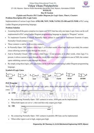
- 1. Vidya Vikas Educational Trust (R), Vidya Vikas Polytechnic 27-128, Mysore - Bannur Road Alanahally,Alanahally Post, Mysuru, Karnataka 570028 Prepared by: Mr Thanmay J.S, H.O.D Mechanical Engineering VVETP, Mysore WEEK 02 Day 01 Session Explain and Practice PLC Ladder Diagram for Logic Gates, Timers, Counters Problem Description (01): Logic Gates Implementation of various Logic Gates AND, OR, NOT, NOR, NAND, EX-OR and EX-NOR in PLC using Ladder Diagram programming language. Problem Solution • Assuming that all the gates comprise two inputs and NOT Gate has only one input, Logic Gates can be well implemented in PLC using Ladder Diagram programming language as shown in “Program” section. • To implement Examine if closed, Normally Open contact is used and to implement Examine if open, Normally Closed contact is used. • These contacts is said to work as relay contacts. • In Normally Open / XIC contact, when logic 1, or in other words, when logic high is provided, the contact closes allowing current to pass through the circuit. • And in Normally Closed / XIO contact, when logic 1 is not present, or in other words, when logic 0 is present, it allows current to pass through the circuit. But when logic 1 is present in case of XIO, the contact opens inhibiting current to pass through the circuit. • By simply using these logics, all Logic Gates can be well implemented using Ladder Diagram programming language. Symbol of Logic Gates PLC Program Here is PLC program to implement various logic gates, along with program explanation and run time test cases. a) AND • By connecting Normally Open / XIC contacts in series, AND gate can be implemented. • When both inputs are set to 1, then and then only output goes high. b) OR • By connecting Normally Open / XIC contacts in parallel, OR Gate can be implemented. • When either input is set to high, output goes high.
- 2. Vidya Vikas Educational Trust (R), Vidya Vikas Polytechnic 27-128, Mysore - Bannur Road Alanahally,Alanahally Post, Mysuru, Karnataka 570028 Prepared by: Mr Thanmay J.S, H.O.D Mechanical Engineering VVETP, Mysore c) NOT • By using just one Normally Closed / XIO contact, NOT Logic Gate can be implemented. • Inverted state of input is obtained as an output. d) NOR • By connecting Normally Closed / XIO contacts in series, NOR Logic Gate can be implemented. • If both inputs are Reset to 0, output goes High otherwise remains in Low state. • Or by inverting output of a OR Gate, that is by using output of OR Gate as an input of NOT Gate, NOR Gate can be implemented. e) NAND • By connecting Normally Closed contacts in parallel to each other, NAND Gate can be implemented. • Or by simply inverting output of AND gate, NAND Gate can be implemented. f) EX-OR • By connecting XIC and XIO in series with parallel to XIO and XIC in series as shown in diagram above, EX-OR Gate can be implemented. • When both inputs are identical, output is 0. Output is high when A ≠ B. • Note here that XIC of first series contacts and XIO of second series contacts must be given same address and similarly for the other two. g) EX-NOR • By connecting two XIO contacts in series with parallel to two XIC contacts in series, EX-NOR gate can be implemented. • When both inputs are identical A=B=O or A=B=1, output goes high. • It implies same here as in EX-OR gate that address must be given same. • By inverting output of EX-OR gate, implementation of EX-NOR can be accomplished.
- 3. Vidya Vikas Educational Trust (R), Vidya Vikas Polytechnic 27-128, Mysore - Bannur Road Alanahally,Alanahally Post, Mysuru, Karnataka 570028 Prepared by: Mr Thanmay J.S, H.O.D Mechanical Engineering VVETP, Mysore Runtime Test Cases Inputs Outputs A B AND OR NOR NAND EX-OR EX-NOR 0 0 0 0 1 1 0 1 0 1 0 1 0 1 1 0 1 0 0 1 0 1 1 0 1 1 1 1 0 0 0 1 Inputs Output A NOT 0 1 1 0 Problem Description (02): Timers Implement PLC using Ladder Diagram programming language using timers. Steps: 1) Go to Software RSLogix 500 and choose the CPU 2) Create Start and Stop as Digital Inputs, used in all control process 3) Create B3:0 Binary In others PLCs you may find as "FLAGS" - "M", are Contacts in a PLC that create better logic in the programming 4) Select Timer TON and Start Editing • Edit TON T4:0 The Main block of Timer On Delay "TON" here we configure: • Timer: Number and Adress of Timer, the Block configuration is in the side and is called TIMER T4 • Time Base: The number of times of "Seconds", a Time Base 1.0, means 1 second • Preset: The Limit of the seconds counted, when limit is reached Activate the Timer Output "DN" • Accum: Register the Seconds Counting when TON is energized, when TON is not energized Accum back to "0" 5) Then select the Timer Block and configure all parameters from image, the address important in this case is "DN" and will close a Contact when Preset Value has reached by Accum in the Timer Block
- 4. Vidya Vikas Educational Trust (R), Vidya Vikas Polytechnic 27-128, Mysore - Bannur Road Alanahally,Alanahally Post, Mysuru, Karnataka 570028 Prepared by: Mr Thanmay J.S, H.O.D Mechanical Engineering VVETP, Mysore Ladder Diagram: Problem Description (03): Counters Implement PLC using Ladder Diagram programming language using Counter. • A Micrologix 1100 Allen Bradley PLC is used to control a process. • A “Product PROC Sensor ON” is indicated by an internal bit B3:0/13. • A CTU instruction is tied to Counter C5:0. • The Counter C5:0 has a “Preset” of 16. The number 16 represents the number of products in a certain batch. • When the bit B3:0/13 goes HIGH, the CTU instruction is energized and the counter increments the “Preset” value. • When the bit B3:0/16 goes LOW, followed by HIGH, the CTU instruction is energized and the counter increments again. • The counter will continue to increment until “Accum” = 16. • When “Accum” of C5:0 Counter is equal to 16, the C5:0.DN bit is HIGH. • The C5:0.DN bit is used to set an internal bit B3:0/14. • The B3:0/14 bit is used to energize C5:1. This Counter counts how many batches have been completed. • The B3:0/14 bit is also used to RES (Reset) the C5:0 Counter.
- 5. Vidya Vikas Educational Trust (R), Vidya Vikas Polytechnic 27-128, Mysore - Bannur Road Alanahally,Alanahally Post, Mysuru, Karnataka 570028 Prepared by: Mr Thanmay J.S, H.O.D Mechanical Engineering VVETP, Mysore Programming example in RSLogix 500: Data Types Allowed for CTU The CTU leverages a specific data structure, called the Counter, present in most PLC systems. • Counter – The high-level instruction specification of all the inner structures. • .PRE – Integer specifying up to which value the timer will count. • .ACC – Integer specifying the current time value of the timer. • .CU – Boolean value which is set to HIGH when the counter is energized to count up. • .CD – Boolean value which is set to HIGH when the counter is energized to count down. • .DN – Boolean value which is set to HIGH when the timer is finished counting. • .OV – Boolean value which is set to HIGH when the counter is overflown. • Note: The overflow status signifies that the counter has reached the logical limit of 32767 and had to wrap back to the value of -32768. • Note2: To avoid overloading the counter, make sure to program proper measures into your software. • .UN – Boolean value which is set to HIGH when the counter is under flown. • Note: The underflow status signifies that the counter has reached the logical limit of -32768 and had to wrap back to the value of 32767. • Note2: To avoid overloading the counter, make sure to program proper measures into your software.
- 6. Vidya Vikas Educational Trust (R), Vidya Vikas Polytechnic 27-128, Mysore - Bannur Road Alanahally,Alanahally Post, Mysuru, Karnataka 570028 Prepared by: Mr Thanmay J.S, H.O.D Mechanical Engineering VVETP, Mysore Week 02 Day 02 Session Explain and Practice PLC Ladder Diagram for Compare, Jump and Subroutines Explain and Practice PLC Ladder Diagram for Math Instructions and Shift Registers Problem Description (03): Compare To study the working of comparator blocks (EQU, NEQ, LES, GRT, LEQ and GEQ) using simple example in Allen Bradley programmable logic controllers (PLC). There are two parameters in each block, Source A & Source B –where values are stored. Description of Comparator Blocks: EQU: Equal block is used to compare the two values stored in Source A and source B and gives output as “1” if both are equal and “0” if both are not equal. LES: Lesser than block is used to compare the two values stored in Source A and source B and gives output as “1” if Source A value is Lesser than Source B value and “0” if Source A value is greater than or equal to Source B value. LEQ: Lesser than or equal to block is used to compare the two values stored in Source A and source B and gives output as “1” if Source A value is lesser than or equal value to Source B value and “0” if Source A value is greater Source B value. NEQ: Not equal block is used to compare the two values stored in Source A and source B and gives output as “1” if Source A value is not same as Source B value and “0” if Source A value is same as Source B value. GRT: Greater than block is used to compare the two values stored in Source A and source B and gives output as “1” if Source A value is Greater than Source B value and “0” if Source A value is lesser than or equal to Source B value. GEQ: Greater than or equal to block is used to compare the two values stored in Source A and source B and gives output as “1” if Source A value is Greater than or equal value to Source B value and “0” if Source A value is Lesser Source B value.
- 7. Vidya Vikas Educational Trust (R), Vidya Vikas Polytechnic 27-128, Mysore - Bannur Road Alanahally,Alanahally Post, Mysuru, Karnataka 570028 Prepared by: Mr Thanmay J.S, H.O.D Mechanical Engineering VVETP, Mysore Comparator simple example, Program Logic Examples, when start switch is pressed, 1. If water level is below 5, motor should turn ON till water level reach 95. 2. If water level indicates the value below 5, low level water alarm should ON. 3. If water level indicates the value above 95, high level water alarm should ON. 4. If water level is exactly at 95, steamer should turn ON. 5. System under control indication should always ON when Water level is not equal to 100. PLC Input Output List Logic Description: RUNG 0000: When Start switch is pressed, N7:0 is the water level value which is Compared with 5 and 95 using GEQ and LEQ block to turn ON Motor. (i.e-Motor should turn ON if water level is between 5 and 95) RUNG 0001: Low level alarm is triggered, when water level goes below 5. Less than block is used to perform this function. RUNG 0002: High level alarm is triggered, when water level goes above 95. Greater than (GRT) block is used to perform this function. RUNG 0003: Steamer output is turned ON when water level reached exactly at 95. RUNG 0004: System under control output always in ON condition when water level is not at 100. PLC Comparator Programming
- 8. Vidya Vikas Educational Trust (R), Vidya Vikas Polytechnic 27-128, Mysore - Bannur Road Alanahally,Alanahally Post, Mysuru, Karnataka 570028 Prepared by: Mr Thanmay J.S, H.O.D Mechanical Engineering VVETP, Mysore Problem Description (04): Jump Jump instruction in ladder logic is used to skip some process or rungs according to the requirement. It is paired with Label which is used to limit the skipping the process. Example – JUMP Instruction in PLC Ladder Logic There are seven motors used for various processes. On-demand base Motors 4, 5 & 6 are needed. Design a program to skip motor 4, 5 & 6 when it does require for the process. Program Description RUNG 0000: The input I:0/0 is used to turn on Motor 1. RUNG 0001: The input I:0/1 is used to turn on Motor 2. RUNG 0002: The input I:0/2 is used to turn on Motor 3. RUNG 0003: The input I:0/3 is used to initiate the jump function (Q2:0). RUNG 0004: The input I:0/0 & I:0/4 is used to turn on Motor 4. RUNG 0005: The input I:0/1 and I:0/5 is used to turn on Motor 5. Rung 0007: Label instruction is used to finish the jump function. The input I:0/6 and I:0/2 is used to turn on Motor 6. When Jump condition is OFF: All outputs will turn ON/OFF according to respective input. When Jump condition is ON: Rung 4, 5 & 6 are completely skipped till label function.
- 9. Vidya Vikas Educational Trust (R), Vidya Vikas Polytechnic 27-128, Mysore - Bannur Road Alanahally,Alanahally Post, Mysuru, Karnataka 570028 Prepared by: Mr Thanmay J.S, H.O.D Mechanical Engineering VVETP, Mysore Problem Description (05): Subroutine This is a PLC Program to Call a Subroutine for a Different Process. Problem Description Add temperature outputs of two temperature transmitters and display the total temperature. Update display every 10 seconds when this system is active using Subroutine program. Problem Solution • Using subroutine has an advantage that process is not affected by any other data in subroutine program unless and until the subroutine is called. • This is very useful in displaying various data on the same display with a particular time delay. • For example, we can use the same display to show Pressure readings for the first 5 seconds and Temperature reading for the next five seconds and so on. • When we use subroutine instruction, Subroutine address must be same in JSR instruction of main program and RET instruction of subroutine program.
- 10. Vidya Vikas Educational Trust (R), Vidya Vikas Polytechnic 27-128, Mysore - Bannur Road Alanahally,Alanahally Post, Mysuru, Karnataka 570028 Prepared by: Mr Thanmay J.S, H.O.D Mechanical Engineering VVETP, Mysore PLC Program Here is PLC program to Call a Subroutine for a Different Process, along with program explanation and run time test cases. List of Inputs and Outputs I:1/0 = Start (Input) I:1/1 = Stop (Input) O:2/0 = Master Coil (Output) T4:0 = Time delay to update data (Timer) O:6 = Display address (Output) N7:0 & N7:1 = Temperature data of transmitters (Register) T4:0/DN = Update display calling Subroutine, reset timer (Timer Bit) U:3 = Address of Subroutine (Subroutine) Ladder Diagram to call subroutine Ladder Diagram of subroutine (Name: U 3)
- 11. Vidya Vikas Educational Trust (R), Vidya Vikas Polytechnic 27-128, Mysore - Bannur Road Alanahally,Alanahally Post, Mysuru, Karnataka 570028 Prepared by: Mr Thanmay J.S, H.O.D Mechanical Engineering VVETP, Mysore Program Description • Main program comprises of simple Master Coil rung, rung for timer and rung to call subroutine. • When Start PB I:1/0 is pressed, Master coil energizes and the TON timer T4:0 is enabled. • After 10 seconds when PRESET=ACCUMULATOR, T4:0/DN bit goes high calling subroutine. • Subroutine has a program that adds two data from addresses N7:0 and N7:1 which are outputs from Temperature transmitters. These outputs are added and output of addition is converted into BCD and sent to address O:6 which is connected to Display. • Output data are in Hexadecimal and Displays accept BCD inputs. So TOD instruction is used here to convert data of temperature addition to BCD. • T4:0/DN is also used as an XIO input to Timer itself, hence it automatically resets to 0 whenever preset and accumulator values are equal or in other words, it updates the display every 10secs resetting timer. Runtime Test Cases Display value is modified every 10secs
- 12. Vidya Vikas Educational Trust (R), Vidya Vikas Polytechnic 27-128, Mysore - Bannur Road Alanahally,Alanahally Post, Mysuru, Karnataka 570028 Prepared by: Mr Thanmay J.S, H.O.D Mechanical Engineering VVETP, Mysore Problem Description (06): Math Instructions This is a PLC Program to do Mathematical Functions. Problem Description Implement various mathematical functions in PLC using Ladder Diagram programming language. Problem Solution • Use all the Math Instructions to implement various Mathematical Arithmetic Functions. • Use ADD to add one piece of data to another. • Use SUB to subtract one piece of data from another. • Use MUL to multiply one piece of data by another. • Use DIV to divide one piece of data by another. • Use SQR to find the square root of a piece of data. • Use NEG to change the sign of a piece of data. PLC Program Here is PLC program to do Mathematical Functions, along with program explanation and run time test cases. List of Inputs and Outputs I:1/0 = Input to Add (Input) I:1/1 = Input to Subtract (Input) I:1/2 = Input to Multiply (Input) I:1/3 = Input to Divide (Input) I:1/4 = Input to find Square Root (Input) I:1/5 = Input to change the sign of a Number (Input) N:7/0 to N:7/9 = Integer Number Location (Input) O:6 = Display (Output)
- 13. Vidya Vikas Educational Trust (R), Vidya Vikas Polytechnic 27-128, Mysore - Bannur Road Alanahally,Alanahally Post, Mysuru, Karnataka 570028 Prepared by: Mr Thanmay J.S, H.O.D Mechanical Engineering VVETP, Mysore Ladder Diagram to implement mathematical arithmetic functions Program Description • Program is very clear to understand. • N7:0 to N7:9 contain Integers of which operation is to be performed. • In the ADD instruction, data of N7:0 and N7:1 are added and sent to destination which is Display with output address O:6. • Similarly, all other operations are performed. • Though, we must know that the answers stored in the destination are in Hexadecimal form, hence we have to convert this data into BCD form and then send it to display output O:6.
- 14. Vidya Vikas Educational Trust (R), Vidya Vikas Polytechnic 27-128, Mysore - Bannur Road Alanahally,Alanahally Post, Mysuru, Karnataka 570028 Prepared by: Mr Thanmay J.S, H.O.D Mechanical Engineering VVETP, Mysore Problem Description (07): Shift Registers This is a PLC Program to Control Lights in a Sequence (2). Problem Description Implement controlling of various lights in PLC using Ladder Diagram programming language using Bit Shift Registers. Problem Solution • Define order of lights. • Use Bit Shift Registers to implement any sequence of lights. • Double check if the order of light is made correctly and connections are made properly. • Use latching coil for Master Start and Stop for prevention against malfunctioning. • 0.1 Time Base function availability is useful to shift register bits very quickly. • By using this, we can make lights blink. • Check if bit addresses provided to Light output addresses are correctly chosen or not. • Provide 16bit of length to Bit Shift Register, by adding this total 16 number of lights can be controlled. • This limitation can be overcome by using more than one registers or with same length, more than one shift registers. PLC Program Here is PLC program to Control Lights in a Sequence, along with program explanation and run time test cases. List of Inputs and Outputs I:1/0 = Master Start (Input) B3:0 = Altering Register (Output Register) R6:0 = Control Register (Storing Register) R6:0/UL= Used for Wraparound operation (Unload Bit) B3:0/0 = Bit input to Output 0 (Input Bit) O:2/0 = Output 0 (Output) B3:0/1 = Bit input to Output 1 (Input Bit) O:2/1 = Output 1 (Output) B3:0/2 = Bit input to Output 2 (Input Bit) O:2/2 = Output 2 (Output) B3:0/3 = Bit input to Output 3 (Input Bit) O:2/3 = Output 3 (Output) T4:0 = Timer to shift bits (Timer)
- 15. Vidya Vikas Educational Trust (R), Vidya Vikas Polytechnic 27-128, Mysore - Bannur Road Alanahally,Alanahally Post, Mysuru, Karnataka 570028 Prepared by: Mr Thanmay J.S, H.O.D Mechanical Engineering VVETP, Mysore Ladder Diagram to solve this problem Program Description • Here in the Ladder Diagram, Outputs are controlled by the bits set in the register B3:0. • These outputs are controlled in accordance to shifting of bits from Right to Left. • This shifting is controlled by Timer T4:0. • Timer is set to auto reset mode by setting XIO T4:0/DN bit of the same timer to its input. Master Start is included as well. This has to be a toggle switch otherwise latching rung is used in case Push Buttons are available and one more Stop PB must be added to Master Stop. • Whenever Timer Done bit is set, that bit sends False to True signal to Bit Shift Register which performs Shifting of bits to Left. • Time delay is 0.1secs here, so that shifting is really quick. • Length indicates the number of bits to be shifted, or the file length in, in bits. • The Last bit is shifted out of the array and stored in the unload bit, R6:0/UL. The status that was previously in the unload bit is lost. So, for wraparound condition, last bit of the array B3:0/0 is set to the position to the UL bit. • After every 0.1secs, bits are shifted and orders outputs are controlled.
- 16. Vidya Vikas Educational Trust (R), Vidya Vikas Polytechnic 27-128, Mysore - Bannur Road Alanahally,Alanahally Post, Mysuru, Karnataka 570028 Prepared by: Mr Thanmay J.S, H.O.D Mechanical Engineering VVETP, Mysore • The sequence of this outputs can be set by setting sequence of bits in the register B3:0 manually or automatically storing sensors’ outputs. Runtime Test Cases • Bits are shifted and Outputs are changed after every 0.1secs. • Outputs are true in the sequence and go false in the same sequence if this bit pattern in the Register B3:0 is followed. • You can set your own pattern and operate outputs accordingly.
- 17. Vidya Vikas Educational Trust (R), Vidya Vikas Polytechnic 27-128, Mysore - Bannur Road Alanahally,Alanahally Post, Mysuru, Karnataka 570028 Prepared by: Mr Thanmay J.S, H.O.D Mechanical Engineering VVETP, Mysore WEEK 02 Day 03 Session: Explain and Practice PLC Program using Functional Block Diagram Dear Students Before we start to attain knowledge of great resource let me remind you to use the proper licensed version of The Logo Soft Comfort Software. LOGO! Software supports small automation projects with simple and intuitive configuration and operation, from the engineering software LOGO! Soft Comfort, to the LOGO! Access Tool, and also the LOGO! Web Editor for the web server integrated into LOGO! The demo version allows to easily test and get acquainted with LOGO! Soft Comfort. You can create, simulate, archive and print out switching programs for all LOGO! devices on PC. Restriction: You cannot transfer switching programs in LOGO! or communicate online with the LOGO! This is only possible with the full version of the software. The demo version allows to transfer programs which have been created with the demo version to LOGO! The free WBT is an ideal addition to the LOGO! programming training.The download contains the necessary files for the operating systems supported by LOGO! Soft Comfort V8 (Windows, Linux and MacOSx). You can find license conditions and disclaimers for Open Source software. You can download the latest version of LOGO! Soft Comfort by using the link below based on your system configurations: https://new.siemens.com/global/en/products/automation/systems/industrial/plc/logo/logo-software.html or https://support.industry.siemens.com/cs/document/109782616/logo!-soft-comfort-v8-demo?dti=0&lc=en- WW If you insist on using the same version as mine download from any of the links below but be alert for virus and pirated versions, try not to use crack use demo version for best results, also be cautious in x32 bit or x64 bit Installation: https://plc247.com/download-logo-soft-comfort-v8-3-full-version/ I request all those who use this manual to support “Siemens Technology” for their innovative software LOGO! Soft Comfort. For contact and support use the links below: https://support.industry.siemens.com/cs/products?dtp=ExampleOfUse&mfn=ps&pnid=13632&lc=en-WW Thanking you all With regards THANMAY J S
- 18. Vidya Vikas Educational Trust (R), Vidya Vikas Polytechnic 27-128, Mysore - Bannur Road Alanahally,Alanahally Post, Mysuru, Karnataka 570028 Prepared by: Mr Thanmay J.S, H.O.D Mechanical Engineering VVETP, Mysore Working with Logo! Soft Comfort Step (1): Open Logo! Soft Comfort and Click Down arrow on “New” command and Select “Function Block Diagram” Step (2): Using Constants select desirable circuit blocks and arrange in the Interface. Step (3): Use Tool Bars to joint the circuits or giving comments Step (4): Press “F3” or simulate for analysis
- 19. Vidya Vikas Educational Trust (R), Vidya Vikas Polytechnic 27-128, Mysore - Bannur Road Alanahally,Alanahally Post, Mysuru, Karnataka 570028 Prepared by: Mr Thanmay J.S, H.O.D Mechanical Engineering VVETP, Mysore Problem Description (08): PLC Program using Functional Block Diagram a) AND Gate b) OR Gate c) Timer Function Block d) Counter Function Block
- 20. Vidya Vikas Educational Trust (R), Vidya Vikas Polytechnic 27-128, Mysore - Bannur Road Alanahally,Alanahally Post, Mysuru, Karnataka 570028 Prepared by: Mr Thanmay J.S, H.O.D Mechanical Engineering VVETP, Mysore Week 02 Day 04 Session: Explain and Practice PLC Program using Structural Text language Dear Students The OpenPLC Editor is a IEC 61131-3 compliant PLC editor totally free and open source. OpenPLC is an open-source Programmable Logic Controller that is based on an easy-to-use software. It is the first fully functional standardized open-source PLC, both in software and in hardware. The OpenPLC project was created in accordance with the IEC 61131-3 standard, which defines the basic software architecture and programming languages for PLCs. OpenPLC is mainly used on industrial and home automation, internet of things and SCADA research. OpenPLC Editor can run on any platform that has support for Python. Currently there are official for: • Windows • Linux (Debian, Ubuntu, Fedora and variants) • macOS (currently in beta) For the officially supported platforms, just download the provided installer for your Operating System from the OpenPLC website, and follow the instructions on the screen to have it installed in your system. You can download free version by following link below https://openplcproject.com/download/ I request all those who use this manual to support “OpenPLC program” and to support their vision for providing such a extraordinary tool for PLC Programming. I also request the students to visit their service section for further details. https://openplcproject.com/sponsor/ Thanking you all With regards THANMAY J S
- 21. Vidya Vikas Educational Trust (R), Vidya Vikas Polytechnic 27-128, Mysore - Bannur Road Alanahally,Alanahally Post, Mysuru, Karnataka 570028 Prepared by: Mr Thanmay J.S, H.O.D Mechanical Engineering VVETP, Mysore Working with OpenPLC Editor Step 01: OpenPLC Editor, Select New and click Language type as “ST” after giving a File Name. Step 02: Add Variables that are required and assign Type (Example BOOL) Step 03: Type the Structured Text Program Step 04: Start PLC Simulation Step 05: Click Debug symbol in Left and Check Debugger Output in right side. Step 06: If you click the padlock, you can set the value in a new popup: Step 06: Toggle the Input Value and check the Output
- 22. Vidya Vikas Educational Trust (R), Vidya Vikas Polytechnic 27-128, Mysore - Bannur Road Alanahally,Alanahally Post, Mysuru, Karnataka 570028 Prepared by: Mr Thanmay J.S, H.O.D Mechanical Engineering VVETP, Mysore Introduction to Structured Text Programming [ST] After practicing with ladder logic (LL) in OpenPLC, structured text (ST) programming will be practiced. While (LL) is a visual method of programming PLCs, ST is a C-like language for programming PLCs, featuring well-known coding functions such as IF and WHILE. OpenPLC also allows you to program PLCs using ST There is one minor difference; with Ladder Logic, OpenPLC can simulate the circuit and get a pretty visualisation based on the LL design itself. With ST, because there is no design, there is no pretty visualisation. However, the Debugger does give a timeline of the states of the various variables, and it can be used to force a value, so you can still simulate a circuit. Structured Text You’ll see the code below, but a few things about the language first: • A mandatory semicolon; ends each statement • IF is closed with END_IF, requires THEN, and brackets are not used • := is used for variable assignment Problem Description (09): Example for PLC Program using Structured Text [ST] Let’s recreate the basic designs I created with LL before in OpenPLC and get them running on the Arduino. The physical Arduino circuit is the same as before (see here), and of course OpenPLC is installed and configured in the same way also (see here). Two-Button Latching Circuit The variables are the same as before: The code is: IF PB1 THEN LED := TRUE; END_IF; IF PB2 THEN LED := FALSE; END_IF; Even if you’ve never done any coding before, I’m sure this will make sense. If PB1 is pressed, set LED to TRUE (on). If PB2 is pressed, turn it off. Note how PB1 doesn’t have to be physically held on to keep LED on; once it is pressed, LED is set to TRUE, and this stays until it is changed. With LL we needed a contact linked to the LED in parallel with the push button to latch it; in ST, it’s effectively self-latching.
- 23. Vidya Vikas Educational Trust (R), Vidya Vikas Polytechnic 27-128, Mysore - Bannur Road Alanahally,Alanahally Post, Mysuru, Karnataka 570028 Prepared by: Mr Thanmay J.S, H.O.D Mechanical Engineering VVETP, Mysore To simulate this in OpenPLC, click the Simulate button and let it compile and start etc: Next, click Debug on the left panel: A new tab will appear, and the person will become a STOP sign: On right panel, it will change to the Debugger tab, but currently it’s empty: To Debug (view) the individual variables, click the glasses icon for each in the left panel: They will appear in the right panel: If you hover over then double-click, we get visuals!
- 24. Vidya Vikas Educational Trust (R), Vidya Vikas Polytechnic 27-128, Mysore - Bannur Road Alanahally,Alanahally Post, Mysuru, Karnataka 570028 Prepared by: Mr Thanmay J.S, H.O.D Mechanical Engineering VVETP, Mysore Repeat for all, and then if you hover over the visual, you can change the size. I like the middle-size one: Now, if you hover over the value (in this case, False), you get a new menu: If you click the padlock, you can set the value in a new popup: Click Toggle value then OK, and the chart will change: And note how this has turned the LED on!
- 25. Vidya Vikas Educational Trust (R), Vidya Vikas Polytechnic 27-128, Mysore - Bannur Road Alanahally,Alanahally Post, Mysuru, Karnataka 570028 Prepared by: Mr Thanmay J.S, H.O.D Mechanical Engineering VVETP, Mysore You can force all the values all the values this way to see the behaviour. Note you’ll have to Toggle the PB1 both on and off (TRUE and FALSE) to simulate pressing and releasing the button. If the speed is too fast, you can change the Duration setting in the Debugger. I found 30s good. Here’s the full “routine” - PB1 TRUE (LED TRUE) then FALSE, then PB2 TRUE (LED FALSE) then FALSE: Interestingly, if you hold PB2 TRUE (i.e. keep the button pressed), LED stays FALSE even if you press PB1. This is because, in the ST, the code for PB2 comes after the code for PB1 Changing the code around it Creates the opposite effect: IF PB2 = TRUE THEN LED := FALSE; END_IF; IF PB1 = TRUE THEN LED := TRUE; END_IF;
- 26. Vidya Vikas Educational Trust (R), Vidya Vikas Polytechnic 27-128, Mysore - Bannur Road Alanahally,Alanahally Post, Mysuru, Karnataka 570028 Prepared by: Mr Thanmay J.S, H.O.D Mechanical Engineering VVETP, Mysore Also, if you decrease the Duration enough, you can see the ramp for the change: Uploading to the Arduino works in the same way as with LL and creates the same result as the Debugger. Unsurprising, really. Problem Description (09): Example One-Button Latching Circuit with Emergency Stop Next one! The initial thought is this: IF PB1 AND NOT PB2 THEN LED := NOT LED; END_IF; IF PB2 THEN LED := FALSE; END_IF; The second line, quite simply, toggles the value of LED to the opposite of what it was. TRUE becomes FALSE, and FALSE becomes TRUE. If PB2 (emergency stop) is pressed, this will not happen. And whatever value LED is, if PB2 is pressed, the LED goes off. However, this creates a strange effect: Let’s zoom in by changing the Duration: On the actual Arduino, this is the LED flashing continuously. Why is this? Well, PLC code loops continuously. This means, every loop, it sees PB1 high, and toggles LED. Not quite what we want.
- 27. Vidya Vikas Educational Trust (R), Vidya Vikas Polytechnic 27-128, Mysore - Bannur Road Alanahally,Alanahally Post, Mysuru, Karnataka 570028 Prepared by: Mr Thanmay J.S, H.O.D Mechanical Engineering VVETP, Mysore The solution is using states; in particular, using a variable to log the previous state of PB1, and only do something if the previous state has changed. So, we add a new variable, PB1_PREV (note this does not relate to anything physical; it is purely a variable): And the code looks like this: IF PB1 AND NOT PB1_PREV AND NOT PB2 THEN LED := NOT LED; END_IF; PB1_PREV := PB1; IF PB2 THEN LED := FALSE; END_IF; This is the same as before, but each loop, PB1_PREV is set to be the same as PB1, and the IF only functions if PB1 is not equal to PB1_PREV. Here is the full functionality, both turned on and off by PB1, and an emergency stop caused by PB2 even though PB1 was still TRUE (and, if PB2 is TRUE, PB1 has no effect): Day 05 Session: Developmental Weekly Assessment + Industry Assignment Day 06 Session: Industry Class on PLC Programs practiced in Industry + Industry Assignment