2 c industrial hydraulic circuits
•Download as PPTX, PDF•
1 like•467 views

industrial hydraulic circuits

Recommended
More Related Content
What's hot
What's hot (20)
Similar to 2 c industrial hydraulic circuits
Similar to 2 c industrial hydraulic circuits (20)
More from Dr.R. SELVAM
More from Dr.R. SELVAM (20)
Recently uploaded
Recently uploaded (20)
2 c industrial hydraulic circuits
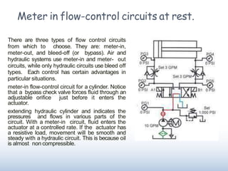
- 1. Meter in flow-control circuits at rest. There are three types of flow control circuits from which to choose. They are: meter-in, meter-out, and bleed-off (or bypass). Air and hydraulic systems use meter-in and meter- out circuits, while only hydraulic circuits use bleed off types. Each control has certain advantages in particular situations. meter-in flow-control circuit for a cylinder. Notice that a bypass check valve forces fluid through an adjustable orifice just before it enters the actuator. extending hydraulic cylinder and indicates the pressures and flows in various parts of the circuit. With a meter-in circuit, fluid enters the actuator at a controlled rate. If the actuator has a resistive load, movement will be smooth and steady with a hydraulic circuit. This is because oil is almost non compressible.
- 2. Meter-in flow-control circuit with cylinder extending. ■ In pneumatic systems, cylinder movement may be jerky becauseair iscompressible. ■ As air flows into a cylinder, as depicted in Figure, pressure increases slowly until it generates the breakaway force needed to start the load moving. Because the subsequent force needed to keep the load moving is always less than the breakaway force, the air in the cylinder actually expands. ■ The expanding air increases the cylinder speed, causing it to lunge forward. ■ The piston moves faster than the incoming air can fill the cylinder, pressure drops to less than it takes to keep the cylinder moving andit stops. ■ Then pressure starts to build again to overcome breakaway force and the process repeats. This lunging movement can continue to the end of the stroke. A meter-out circuit is the best control to avoid air-cylinder lunging.
- 3. Meter-in flow-control circuit for overrunning load with cylinderextending ■ If the actuator hasan overrunning load, ameter-in flow controlwill not work. ■ When the directional valve shifts, the vertical load on the cylinder rod makesit extend. ■ Becausefluid cannot enter the cylinder ’scapend fast enough, a vacuum void forms there. The cylinder thenfree falls, regardless of the setting of the meter-in flow adjustment. ■ The pump will continue to supply metered fluid to the cap end of the cylinder and will eventually fill the vacuum void. After the vacuum void fills, the cylinder can produce full force.
- 4. Meter-in control circuit Fig. shows the meter-in circuit. In this flow control valve is connected between the D.C valve and blind end of the cylinder. Here metered fluid enters the cylinder which controls the speed and feed of the piston. When D.C. valve is manually shifted to right side the flow from pump passes through the compensated flow control valve into blind end of cylinder and the exhaust fluid is directed freely to the reservoir.
- 5. Meter-out speed control circuit Fig. shows meter-out speed control circuit. In this flow control valve is located between D.C. valve and rod end of cylinder in such a way that the fluid is metered as it leaves the cylinder. When D.C. valve is manually shifted to right side the flow from pump passes to blind end of cylinder and the exhaust fluid is directed through flow control valve to the reservoir. Due to this the movement of piston is regulated as fluid has restriction on rod end side. Thus piston moves slowly.
- 6. Bleed-off control circuit This is basic speed control circuit in which the flow control valve is used to divert the fluid to the reservoir. Fig. shows bleed-off control circuit. In this flow control valve is connected in the pressure line so that the speed control may be in both directions of cylinder travel. These circuits are suitable for broaching machines, shaping and planning machines. The bleed-off control circuits may be used in hydraulic motor brake circuit and concrete mixtures on the truck.
- 7. Sequence circuit In this sequence valve is provided to do the operations sequentially. Fig. shows the use of two sequence valve in hydraulic circuit for controlling two operations performed in the sequence in both directions. It consist of hydraulic power unit, two sequence valves A & B with integral check valve, two double acting cylinders P & Q, and D.C. valve When D.C. valve is shifted to left envelop mode, the oil from pump enters the cylinder ‘P’ through line 1-3, causing the piston in cylinder ‘P’ to extend fully.
- 8. Application of Hydraulic circuits Hydraulic circuit for Milling M/c Hydraulic circuit for Shaper M/c Hydraulic circuit for Surface grinder Hydraulic circuit for Hydraulic Press Hydraulic Power Steering Reaction piston type hydraulic steering system Hydraulic circuit of Dumpers Hydraulic circuit of Excavators