SlideShare a Scribd company logo
1 of 4
5-3. Flow-Control Valves 
Flow-control valves are used to control an actuator's speed by metering flow. Metering is 
measuring or regulating the flow rate to or from an actuator. A water faucet is an example of a 
flow-control valve. Flow rate varies as a faucet handle is turned clockwise or counterclockwise. In 
a closed position, flow stops. Many flow-control valves used in fluid-powered systems are similar 
in design and operation to a water faucet's. 
In hydraulic circuits, flow-control valves are generally used to control the speed of hydraulic 
motors and work spindles and the travel rates of tool heads or slides. Flow-control valves 
incorporate an integral pressure compensator, which causes the flow rate to remain substantially 
uniform regardless of changes in workload. A nonpressure, compensated flow control, such as a 
needle valve or fixed restriction, allows changes in the flow rate when pressure drop through it 
changes. 
Variations of the basic flow-control valves are the flow-control-and-check valves and the flow-control- 
and-overload relief valves. Models in the flow-control-and-check-valve series incorporate 
an integral check valve to allow reverse free flow. Models in the flow-control-and-overload-relief-valve 
series incorporate an integral relief valve to limit system pressure. Some of these valves are 
gasket-mounted, and some are panel-mounted. 
a. Gate Valve. In this type of valve, a wedge or gate controls the flow. To open and close a 
passage, a handwheel moves a wedge or gate up and down across a flow line. Figure 5-30 
shows the principal elements of a gate valve. Area A shows the line connection and the outside 
structure of the valve; area B shows the wedge or gate inside the valve and the stem to which the 
gate and the handwheel are attached. When the valve is opened, the gate stands up inside the 
bonnet with its bottom flush with the wall of the line. When the valve is closed, the gate blocks the 
flow by standing straight across the line where it rests firmly against the two seats that extend 
completely around the line.
A gate valve allows a straight flow and offers little or no resistance to the fluid flow when the valve 
is completely open. Sometimes a gate valve is in the partially open position to restrict the flow 
rate. However, its main use is in the fully open or fully closed positions. If the valve is left partly 
open, the valve's face stands in the fluid flow, which will act on the face and cause it to erode. 
b. Globe Valve. A disc, which is screwed directly on the end of the stem, is the controlling 
member of a globe valve. A valve is closed by lowering a disc into a valve seat. Since fluid flows 
equally on all sides of the center of support when a valve is open, there is no unbalanced 
pressure on a disc to cause uneven wear. Figure 5-31 shows a globe valve. 
c. Needle Valve. A needle valve is similar in design and operation to a globe valve. Instead of a 
disc, a needle valve has a long, tapered point at the end of a valve stem. Figure 5-32 shows a 
sectional view of a needle valve. A long taper allows a needle valve to open or close gradually. A 
needle valve is used to control flow: 
 Into delicate gauges, which could be damaged if high-pressure fluid was 
suddenly delivered. 
 At the end of an operation when work motion should halt slowly. 
 At other points where precise flow adjustments are necessary. 
 At points where a small flow rate is desired.
d. Restrictor. A restrictor is used in liquid-powered systems to limit the movement speed of 
certain actuating devices by limiting flow rate in a line. Figure 5-33 shows a fixed restrictor. Figure 
5-34 shows a variable restrictor, which varies the restriction amount and is a modified needle 
valve. This valve can be preadjusted to alter the operating time of a particular subsystem. Also, it 
can be adjusted to meet the requirements of a particular system. 
e. Orifice Check Valve. This valve is used in liquid-powered systems to allow normal speed of 
operation in one direction and limited speed in another. Figure 5-35 shows two orifice check 
valves. 
f. Flow Equalizer. A flow equalizer (flow divider) is used in some hydraulic systems to 
synchronize the operation of two actuating units. An equalizer divides a single stream of fluid from 
a directional-control valve into two equal streams. Each actuating unit receives the same flow 
rate; both move in unison. When the two streams of return fluid operate in opposite directions, a 
flow equalizer combines them at an equal rate. Thus, a flow equalizer synchronizes the actuating 
units' movements during both operational directions.
Figure 5-36 shows one type of flow equalizer; the valve is in the splitting (divided-flow) position. 
Fluid, under pressure from the directional-control valve, enters port 3. This pressure overcomes 
spring tension and forces plug 4 down and uncovers the two orifices in sleeve 2. The fluid then 
splits and should flow equally through side passages 1 and 5. The fluid flows through: 
 Splitting check valves 7 and 15. 
 Metering grooves 10 and 14. 
 Ports 9 and 13. 
 The connecting lines to the actuating cylinders. 
Any difference in the flow rate between the two passages results in a pressure differential 
between these two passages. Free-floating metering piston 11 shifts to equalize the internal 
pressure, equalizing the flow. 
http://www.edgeroamer.com/sweethaven/mechanics/hydraulics01/default.asp?iNum=0503

More Related Content

What's hot

VALVES AND THEIR TYPES
VALVES AND THEIR TYPESVALVES AND THEIR TYPES
VALVES AND THEIR TYPESMadhur Mahajan
 
Basics of Centrifugal Pump
Basics of Centrifugal PumpBasics of Centrifugal Pump
Basics of Centrifugal PumpVikram Sharma
 
Fundamentals -valves
Fundamentals  -valvesFundamentals  -valves
Fundamentals -valvesgobindkhiani
 
Impulse and reaction turbines
Impulse and reaction turbinesImpulse and reaction turbines
Impulse and reaction turbinesYasir Hashmi
 
Flow control valves
Flow control valves Flow control valves
Flow control valves Rahul Sharma
 
Fundamentals of mechanical seals
Fundamentals of mechanical sealsFundamentals of mechanical seals
Fundamentals of mechanical sealsPrem Baboo
 
Centrifugal pump
Centrifugal pumpCentrifugal pump
Centrifugal pumpTarun Kumar
 
Hydraulicturbine 1
Hydraulicturbine 1Hydraulicturbine 1
Hydraulicturbine 1Mood Naik
 
Hydraulic Pumps (Positive displacement pumps)
Hydraulic Pumps (Positive displacement pumps)Hydraulic Pumps (Positive displacement pumps)
Hydraulic Pumps (Positive displacement pumps)Abhishek Patange
 
Mechanical Valve
Mechanical ValveMechanical Valve
Mechanical ValveNathan
 
Hydraulic Maintenance and Troubleshooting
Hydraulic Maintenance and TroubleshootingHydraulic Maintenance and Troubleshooting
Hydraulic Maintenance and TroubleshootingCMA/Flodyne/Hydradyne
 
Pressure control valves
Pressure control valvesPressure control valves
Pressure control valvesPRANAV PATEL
 

What's hot (20)

Pump
PumpPump
Pump
 
VALVES AND THEIR TYPES
VALVES AND THEIR TYPESVALVES AND THEIR TYPES
VALVES AND THEIR TYPES
 
Basics of Centrifugal Pump
Basics of Centrifugal PumpBasics of Centrifugal Pump
Basics of Centrifugal Pump
 
pump.ppt
pump.pptpump.ppt
pump.ppt
 
Fundamentals -valves
Fundamentals  -valvesFundamentals  -valves
Fundamentals -valves
 
Impulse and reaction turbines
Impulse and reaction turbinesImpulse and reaction turbines
Impulse and reaction turbines
 
Hydraulic circuits
Hydraulic circuitsHydraulic circuits
Hydraulic circuits
 
Flow control valves
Flow control valves Flow control valves
Flow control valves
 
Fundamentals of mechanical seals
Fundamentals of mechanical sealsFundamentals of mechanical seals
Fundamentals of mechanical seals
 
Centrifugal pump
Centrifugal pumpCentrifugal pump
Centrifugal pump
 
Hydraulicturbine 1
Hydraulicturbine 1Hydraulicturbine 1
Hydraulicturbine 1
 
Wellheads and Flow Lines.pdf
Wellheads and Flow Lines.pdfWellheads and Flow Lines.pdf
Wellheads and Flow Lines.pdf
 
Hydraulic Pumps (Positive displacement pumps)
Hydraulic Pumps (Positive displacement pumps)Hydraulic Pumps (Positive displacement pumps)
Hydraulic Pumps (Positive displacement pumps)
 
Basics of valves
Basics of valvesBasics of valves
Basics of valves
 
Mechanical Valve
Mechanical ValveMechanical Valve
Mechanical Valve
 
Control Valves Book.pdf
Control Valves Book.pdfControl Valves Book.pdf
Control Valves Book.pdf
 
Hidraulic Symbols
Hidraulic Symbols Hidraulic Symbols
Hidraulic Symbols
 
Hydraulic Maintenance and Troubleshooting
Hydraulic Maintenance and TroubleshootingHydraulic Maintenance and Troubleshooting
Hydraulic Maintenance and Troubleshooting
 
Control valve
Control valveControl valve
Control valve
 
Pressure control valves
Pressure control valvesPressure control valves
Pressure control valves
 

Similar to Flow control valves

Module 3 hydraulic control valves
Module 3 hydraulic control valvesModule 3 hydraulic control valves
Module 3 hydraulic control valvessrinivaspp
 
Hydraulic Valves and Hydraulic System Accessories
Hydraulic Valves and Hydraulic System AccessoriesHydraulic Valves and Hydraulic System Accessories
Hydraulic Valves and Hydraulic System AccessoriesRAHUL THAKER
 
3 valve shafts pneumatics and hydraulics
3 valve shafts pneumatics and hydraulics3 valve shafts pneumatics and hydraulics
3 valve shafts pneumatics and hydraulicsaman520305
 
Boiler doc 06 control valve & actuator
Boiler doc 06   control valve & actuatorBoiler doc 06   control valve & actuator
Boiler doc 06 control valve & actuatorMars Tsani
 
Boiler doc 06 control valve & actuator
Boiler doc 06   control valve & actuatorBoiler doc 06   control valve & actuator
Boiler doc 06 control valve & actuatorMars Tsani
 
application of Direction control valve in automatic transmission
application of Direction control valve in automatic transmissionapplication of Direction control valve in automatic transmission
application of Direction control valve in automatic transmissionZIYAD AMBALANGADAN
 
2 c industrial hydraulic circuits
2 c industrial hydraulic circuits2 c industrial hydraulic circuits
2 c industrial hydraulic circuitsDr.R. SELVAM
 
Control Valves .pdf
Control Valves .pdfControl Valves .pdf
Control Valves .pdfmarcos849547
 
chter 3 actuators.pdffejvrvfdvkceckevsvd
chter 3 actuators.pdffejvrvfdvkceckevsvdchter 3 actuators.pdffejvrvfdvkceckevsvd
chter 3 actuators.pdffejvrvfdvkceckevsvdAdugnaGosa1
 
Hydraulic and pneumatic control elements
Hydraulic and pneumatic control elementsHydraulic and pneumatic control elements
Hydraulic and pneumatic control elementsumesh chikhale
 
hydralics lec10 (1).pptx
hydralics lec10 (1).pptxhydralics lec10 (1).pptx
hydralics lec10 (1).pptxLiga8
 
pressurecontrolvalves-161017051912.pptx
pressurecontrolvalves-161017051912.pptxpressurecontrolvalves-161017051912.pptx
pressurecontrolvalves-161017051912.pptxPrathapS46
 
Week 3 1_hydraulics_valve3
Week 3 1_hydraulics_valve3Week 3 1_hydraulics_valve3
Week 3 1_hydraulics_valve3akmal ariffin
 

Similar to Flow control valves (20)

Module 3 hydraulic control valves
Module 3 hydraulic control valvesModule 3 hydraulic control valves
Module 3 hydraulic control valves
 
Hydraulic Valves and Hydraulic System Accessories
Hydraulic Valves and Hydraulic System AccessoriesHydraulic Valves and Hydraulic System Accessories
Hydraulic Valves and Hydraulic System Accessories
 
Flow controll valve
Flow controll valveFlow controll valve
Flow controll valve
 
3 valve shafts pneumatics and hydraulics
3 valve shafts pneumatics and hydraulics3 valve shafts pneumatics and hydraulics
3 valve shafts pneumatics and hydraulics
 
Boiler doc 06 control valve & actuator
Boiler doc 06   control valve & actuatorBoiler doc 06   control valve & actuator
Boiler doc 06 control valve & actuator
 
Boiler doc 06 control valve & actuator
Boiler doc 06   control valve & actuatorBoiler doc 06   control valve & actuator
Boiler doc 06 control valve & actuator
 
application of Direction control valve in automatic transmission
application of Direction control valve in automatic transmissionapplication of Direction control valve in automatic transmission
application of Direction control valve in automatic transmission
 
2 c industrial hydraulic circuits
2 c industrial hydraulic circuits2 c industrial hydraulic circuits
2 c industrial hydraulic circuits
 
Control Valve.pdf
Control Valve.pdfControl Valve.pdf
Control Valve.pdf
 
Control Valves .pdf
Control Valves .pdfControl Valves .pdf
Control Valves .pdf
 
chter 3 actuators.pdffejvrvfdvkceckevsvd
chter 3 actuators.pdffejvrvfdvkceckevsvdchter 3 actuators.pdffejvrvfdvkceckevsvd
chter 3 actuators.pdffejvrvfdvkceckevsvd
 
Hydraulic and pneumatic control elements
Hydraulic and pneumatic control elementsHydraulic and pneumatic control elements
Hydraulic and pneumatic control elements
 
Dc valve
Dc  valve Dc  valve
Dc valve
 
Servo Valves
Servo Valves Servo Valves
Servo Valves
 
hydralics lec10 (1).pptx
hydralics lec10 (1).pptxhydralics lec10 (1).pptx
hydralics lec10 (1).pptx
 
pressurecontrolvalves-161017051912.pptx
pressurecontrolvalves-161017051912.pptxpressurecontrolvalves-161017051912.pptx
pressurecontrolvalves-161017051912.pptx
 
Week 3 1_hydraulics_valve3
Week 3 1_hydraulics_valve3Week 3 1_hydraulics_valve3
Week 3 1_hydraulics_valve3
 
santoshzzz
santoshzzzsantoshzzz
santoshzzz
 
Valve type-modi-11
Valve type-modi-11Valve type-modi-11
Valve type-modi-11
 
Valve type-modi-11
Valve type-modi-11Valve type-modi-11
Valve type-modi-11
 

Recently uploaded

Streamlining Python Development: A Guide to a Modern Project Setup
Streamlining Python Development: A Guide to a Modern Project SetupStreamlining Python Development: A Guide to a Modern Project Setup
Streamlining Python Development: A Guide to a Modern Project SetupFlorian Wilhelm
 
Designing IA for AI - Information Architecture Conference 2024
Designing IA for AI - Information Architecture Conference 2024Designing IA for AI - Information Architecture Conference 2024
Designing IA for AI - Information Architecture Conference 2024Enterprise Knowledge
 
Making_way_through_DLL_hollowing_inspite_of_CFG_by_Debjeet Banerjee.pptx
Making_way_through_DLL_hollowing_inspite_of_CFG_by_Debjeet Banerjee.pptxMaking_way_through_DLL_hollowing_inspite_of_CFG_by_Debjeet Banerjee.pptx
Making_way_through_DLL_hollowing_inspite_of_CFG_by_Debjeet Banerjee.pptxnull - The Open Security Community
 
My Hashitalk Indonesia April 2024 Presentation
My Hashitalk Indonesia April 2024 PresentationMy Hashitalk Indonesia April 2024 Presentation
My Hashitalk Indonesia April 2024 PresentationRidwan Fadjar
 
Scanning the Internet for External Cloud Exposures via SSL Certs
Scanning the Internet for External Cloud Exposures via SSL CertsScanning the Internet for External Cloud Exposures via SSL Certs
Scanning the Internet for External Cloud Exposures via SSL CertsRizwan Syed
 
Automating Business Process via MuleSoft Composer | Bangalore MuleSoft Meetup...
Automating Business Process via MuleSoft Composer | Bangalore MuleSoft Meetup...Automating Business Process via MuleSoft Composer | Bangalore MuleSoft Meetup...
Automating Business Process via MuleSoft Composer | Bangalore MuleSoft Meetup...shyamraj55
 
Connect Wave/ connectwave Pitch Deck Presentation
Connect Wave/ connectwave Pitch Deck PresentationConnect Wave/ connectwave Pitch Deck Presentation
Connect Wave/ connectwave Pitch Deck PresentationSlibray Presentation
 
Key Features Of Token Development (1).pptx
Key  Features Of Token  Development (1).pptxKey  Features Of Token  Development (1).pptx
Key Features Of Token Development (1).pptxLBM Solutions
 
CloudStudio User manual (basic edition):
CloudStudio User manual (basic edition):CloudStudio User manual (basic edition):
CloudStudio User manual (basic edition):comworks
 
"LLMs for Python Engineers: Advanced Data Analysis and Semantic Kernel",Oleks...
"LLMs for Python Engineers: Advanced Data Analysis and Semantic Kernel",Oleks..."LLMs for Python Engineers: Advanced Data Analysis and Semantic Kernel",Oleks...
"LLMs for Python Engineers: Advanced Data Analysis and Semantic Kernel",Oleks...Fwdays
 
How to convert PDF to text with Nanonets
How to convert PDF to text with NanonetsHow to convert PDF to text with Nanonets
How to convert PDF to text with Nanonetsnaman860154
 
Are Multi-Cloud and Serverless Good or Bad?
Are Multi-Cloud and Serverless Good or Bad?Are Multi-Cloud and Serverless Good or Bad?
Are Multi-Cloud and Serverless Good or Bad?Mattias Andersson
 
Understanding the Laravel MVC Architecture
Understanding the Laravel MVC ArchitectureUnderstanding the Laravel MVC Architecture
Understanding the Laravel MVC ArchitecturePixlogix Infotech
 
Unblocking The Main Thread Solving ANRs and Frozen Frames
Unblocking The Main Thread Solving ANRs and Frozen FramesUnblocking The Main Thread Solving ANRs and Frozen Frames
Unblocking The Main Thread Solving ANRs and Frozen FramesSinan KOZAK
 
Injustice - Developers Among Us (SciFiDevCon 2024)
Injustice - Developers Among Us (SciFiDevCon 2024)Injustice - Developers Among Us (SciFiDevCon 2024)
Injustice - Developers Among Us (SciFiDevCon 2024)Allon Mureinik
 
SIEMENS: RAPUNZEL – A Tale About Knowledge Graph
SIEMENS: RAPUNZEL – A Tale About Knowledge GraphSIEMENS: RAPUNZEL – A Tale About Knowledge Graph
SIEMENS: RAPUNZEL – A Tale About Knowledge GraphNeo4j
 

Recently uploaded (20)

Vulnerability_Management_GRC_by Sohang Sengupta.pptx
Vulnerability_Management_GRC_by Sohang Sengupta.pptxVulnerability_Management_GRC_by Sohang Sengupta.pptx
Vulnerability_Management_GRC_by Sohang Sengupta.pptx
 
Streamlining Python Development: A Guide to a Modern Project Setup
Streamlining Python Development: A Guide to a Modern Project SetupStreamlining Python Development: A Guide to a Modern Project Setup
Streamlining Python Development: A Guide to a Modern Project Setup
 
Designing IA for AI - Information Architecture Conference 2024
Designing IA for AI - Information Architecture Conference 2024Designing IA for AI - Information Architecture Conference 2024
Designing IA for AI - Information Architecture Conference 2024
 
DMCC Future of Trade Web3 - Special Edition
DMCC Future of Trade Web3 - Special EditionDMCC Future of Trade Web3 - Special Edition
DMCC Future of Trade Web3 - Special Edition
 
Making_way_through_DLL_hollowing_inspite_of_CFG_by_Debjeet Banerjee.pptx
Making_way_through_DLL_hollowing_inspite_of_CFG_by_Debjeet Banerjee.pptxMaking_way_through_DLL_hollowing_inspite_of_CFG_by_Debjeet Banerjee.pptx
Making_way_through_DLL_hollowing_inspite_of_CFG_by_Debjeet Banerjee.pptx
 
My Hashitalk Indonesia April 2024 Presentation
My Hashitalk Indonesia April 2024 PresentationMy Hashitalk Indonesia April 2024 Presentation
My Hashitalk Indonesia April 2024 Presentation
 
Scanning the Internet for External Cloud Exposures via SSL Certs
Scanning the Internet for External Cloud Exposures via SSL CertsScanning the Internet for External Cloud Exposures via SSL Certs
Scanning the Internet for External Cloud Exposures via SSL Certs
 
The transition to renewables in India.pdf
The transition to renewables in India.pdfThe transition to renewables in India.pdf
The transition to renewables in India.pdf
 
Automating Business Process via MuleSoft Composer | Bangalore MuleSoft Meetup...
Automating Business Process via MuleSoft Composer | Bangalore MuleSoft Meetup...Automating Business Process via MuleSoft Composer | Bangalore MuleSoft Meetup...
Automating Business Process via MuleSoft Composer | Bangalore MuleSoft Meetup...
 
Connect Wave/ connectwave Pitch Deck Presentation
Connect Wave/ connectwave Pitch Deck PresentationConnect Wave/ connectwave Pitch Deck Presentation
Connect Wave/ connectwave Pitch Deck Presentation
 
Key Features Of Token Development (1).pptx
Key  Features Of Token  Development (1).pptxKey  Features Of Token  Development (1).pptx
Key Features Of Token Development (1).pptx
 
E-Vehicle_Hacking_by_Parul Sharma_null_owasp.pptx
E-Vehicle_Hacking_by_Parul Sharma_null_owasp.pptxE-Vehicle_Hacking_by_Parul Sharma_null_owasp.pptx
E-Vehicle_Hacking_by_Parul Sharma_null_owasp.pptx
 
CloudStudio User manual (basic edition):
CloudStudio User manual (basic edition):CloudStudio User manual (basic edition):
CloudStudio User manual (basic edition):
 
"LLMs for Python Engineers: Advanced Data Analysis and Semantic Kernel",Oleks...
"LLMs for Python Engineers: Advanced Data Analysis and Semantic Kernel",Oleks..."LLMs for Python Engineers: Advanced Data Analysis and Semantic Kernel",Oleks...
"LLMs for Python Engineers: Advanced Data Analysis and Semantic Kernel",Oleks...
 
How to convert PDF to text with Nanonets
How to convert PDF to text with NanonetsHow to convert PDF to text with Nanonets
How to convert PDF to text with Nanonets
 
Are Multi-Cloud and Serverless Good or Bad?
Are Multi-Cloud and Serverless Good or Bad?Are Multi-Cloud and Serverless Good or Bad?
Are Multi-Cloud and Serverless Good or Bad?
 
Understanding the Laravel MVC Architecture
Understanding the Laravel MVC ArchitectureUnderstanding the Laravel MVC Architecture
Understanding the Laravel MVC Architecture
 
Unblocking The Main Thread Solving ANRs and Frozen Frames
Unblocking The Main Thread Solving ANRs and Frozen FramesUnblocking The Main Thread Solving ANRs and Frozen Frames
Unblocking The Main Thread Solving ANRs and Frozen Frames
 
Injustice - Developers Among Us (SciFiDevCon 2024)
Injustice - Developers Among Us (SciFiDevCon 2024)Injustice - Developers Among Us (SciFiDevCon 2024)
Injustice - Developers Among Us (SciFiDevCon 2024)
 
SIEMENS: RAPUNZEL – A Tale About Knowledge Graph
SIEMENS: RAPUNZEL – A Tale About Knowledge GraphSIEMENS: RAPUNZEL – A Tale About Knowledge Graph
SIEMENS: RAPUNZEL – A Tale About Knowledge Graph
 

Flow control valves

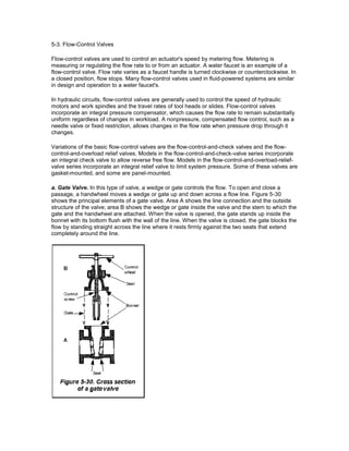
  • 1. 5-3. Flow-Control Valves Flow-control valves are used to control an actuator's speed by metering flow. Metering is measuring or regulating the flow rate to or from an actuator. A water faucet is an example of a flow-control valve. Flow rate varies as a faucet handle is turned clockwise or counterclockwise. In a closed position, flow stops. Many flow-control valves used in fluid-powered systems are similar in design and operation to a water faucet's. In hydraulic circuits, flow-control valves are generally used to control the speed of hydraulic motors and work spindles and the travel rates of tool heads or slides. Flow-control valves incorporate an integral pressure compensator, which causes the flow rate to remain substantially uniform regardless of changes in workload. A nonpressure, compensated flow control, such as a needle valve or fixed restriction, allows changes in the flow rate when pressure drop through it changes. Variations of the basic flow-control valves are the flow-control-and-check valves and the flow-control- and-overload relief valves. Models in the flow-control-and-check-valve series incorporate an integral check valve to allow reverse free flow. Models in the flow-control-and-overload-relief-valve series incorporate an integral relief valve to limit system pressure. Some of these valves are gasket-mounted, and some are panel-mounted. a. Gate Valve. In this type of valve, a wedge or gate controls the flow. To open and close a passage, a handwheel moves a wedge or gate up and down across a flow line. Figure 5-30 shows the principal elements of a gate valve. Area A shows the line connection and the outside structure of the valve; area B shows the wedge or gate inside the valve and the stem to which the gate and the handwheel are attached. When the valve is opened, the gate stands up inside the bonnet with its bottom flush with the wall of the line. When the valve is closed, the gate blocks the flow by standing straight across the line where it rests firmly against the two seats that extend completely around the line.
  • 2. A gate valve allows a straight flow and offers little or no resistance to the fluid flow when the valve is completely open. Sometimes a gate valve is in the partially open position to restrict the flow rate. However, its main use is in the fully open or fully closed positions. If the valve is left partly open, the valve's face stands in the fluid flow, which will act on the face and cause it to erode. b. Globe Valve. A disc, which is screwed directly on the end of the stem, is the controlling member of a globe valve. A valve is closed by lowering a disc into a valve seat. Since fluid flows equally on all sides of the center of support when a valve is open, there is no unbalanced pressure on a disc to cause uneven wear. Figure 5-31 shows a globe valve. c. Needle Valve. A needle valve is similar in design and operation to a globe valve. Instead of a disc, a needle valve has a long, tapered point at the end of a valve stem. Figure 5-32 shows a sectional view of a needle valve. A long taper allows a needle valve to open or close gradually. A needle valve is used to control flow:  Into delicate gauges, which could be damaged if high-pressure fluid was suddenly delivered.  At the end of an operation when work motion should halt slowly.  At other points where precise flow adjustments are necessary.  At points where a small flow rate is desired.
  • 3. d. Restrictor. A restrictor is used in liquid-powered systems to limit the movement speed of certain actuating devices by limiting flow rate in a line. Figure 5-33 shows a fixed restrictor. Figure 5-34 shows a variable restrictor, which varies the restriction amount and is a modified needle valve. This valve can be preadjusted to alter the operating time of a particular subsystem. Also, it can be adjusted to meet the requirements of a particular system. e. Orifice Check Valve. This valve is used in liquid-powered systems to allow normal speed of operation in one direction and limited speed in another. Figure 5-35 shows two orifice check valves. f. Flow Equalizer. A flow equalizer (flow divider) is used in some hydraulic systems to synchronize the operation of two actuating units. An equalizer divides a single stream of fluid from a directional-control valve into two equal streams. Each actuating unit receives the same flow rate; both move in unison. When the two streams of return fluid operate in opposite directions, a flow equalizer combines them at an equal rate. Thus, a flow equalizer synchronizes the actuating units' movements during both operational directions.
  • 4. Figure 5-36 shows one type of flow equalizer; the valve is in the splitting (divided-flow) position. Fluid, under pressure from the directional-control valve, enters port 3. This pressure overcomes spring tension and forces plug 4 down and uncovers the two orifices in sleeve 2. The fluid then splits and should flow equally through side passages 1 and 5. The fluid flows through:  Splitting check valves 7 and 15.  Metering grooves 10 and 14.  Ports 9 and 13.  The connecting lines to the actuating cylinders. Any difference in the flow rate between the two passages results in a pressure differential between these two passages. Free-floating metering piston 11 shifts to equalize the internal pressure, equalizing the flow. http://www.edgeroamer.com/sweethaven/mechanics/hydraulics01/default.asp?iNum=0503