3 industrial hydraulic circuits shapping, milling, drilling
•Download as PPTX, PDF•
1 like•1,503 views

industrial hydraulic circuits shapping, milling, drilling

Recommended
More Related Content
What's hot
What's hot (20)
Similar to 3 industrial hydraulic circuits shapping, milling, drilling
Similar to 3 industrial hydraulic circuits shapping, milling, drilling (20)
More from Dr.R. SELVAM
More from Dr.R. SELVAM (20)
Recently uploaded
Recently uploaded (20)
3 industrial hydraulic circuits shapping, milling, drilling
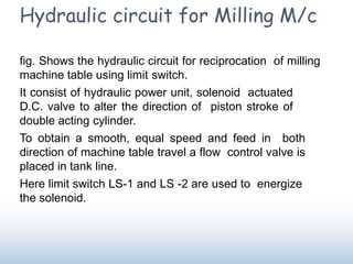
- 1. Hydraulic circuit for Milling M/c fig. Shows the hydraulic circuit for reciprocation of milling machine table using limit switch. It consist of hydraulic power unit, solenoid actuated D.C. valve to alter the direction of piston stroke of double acting cylinder. To obtain a smooth, equal speed and feed in both direction of machine table travel a flow control valve is placed in tank line. Here limit switch LS-1 and LS -2 are used to energize the solenoid.
- 3. Initially consider that the limit switch LS-1 is depressed by machine table which energizes the solenoid C causing D.C. valve to shift in left envelop mode. The oil from pump port ‘P’ enters the cylinder port 1 via line P-A-1 causing machine table to move forward and the oil from other side of piston is return to reservoir through flow control valve At the end of forward stroke the limit switch LS-2 is depressed causing solenoid D to energized. This causes D.C. valve to shift in right envelop mode.
- 4. Then the oil from pump P enters cylinder port 2 causing the piston to perform return stroke. The oil from port 1 returns to reservoir via flow control valve. This cycle is repeated causing milling m/c to perform cutting action. The length & position of stroke can be adjusted by shifting the position of limiting switches
- 5. Hydraulic circuit for Shaper M/c Fig shows the hydraulic circuit for operation of shaper. Here meter- out circuit is used. It consists of hydraulic power unit which delivers the oil at constant pressure. A double acting cylinder is used to reciprocate the ram A pivot actuated D.C. valve is used to alter the direction of stroke of the piston When spool is in right envelop mode, the oil from port P enters the blind end of cylinder causing the ram to move forward.
- 7. The oil from other side of piston is discharged through flow control valve into reservoir. Here quantity of liquid is controlled while going out hence circuit is meter-out. The cutting speed can be changed by controlling the flow control valve. At the end of forward stroke, the ram hits the pivoted lever of D.C. valve shifting the valve into left envelop mode. Thus the oil from pump enters the rod end of the cylinder through check valve causing the ram to perform the return stroke. The oil from blind end returns to reservoir, as there is no restriction the return is quick.
- 8. Hydraulic circuit for Surface grinder Fig. shows the hydraulic circuit for reciprocating the machine table for surface grinder. The circuit consist of a hydraulic power unit, which delivers oil under pressure. It uses pilot operated D.C. valve to alter the direction of stroke of piston in a double acting cylinder. It also consist of two roller actuated three way D.C. valve V1 & V2 to actuate pilot operated four way D.C. valve
- 9. The flow control valve is placed in return line to tank which provides smooth and equal speed and feed in both direction of table travel. When valve V1 is depressed by table, the oil from pump flows through V1 and is supplied to pilot spool E which puts the D.C. valve in left envelop mode Then the oil from pump enters the cylinder through port 1 causing the table to move forward and oil from other side is delivered to reservoir through flow control valve.
- 10. At the end of stroke it depress valve V2 , the oil from pilot line operates spool F to put D.C. valve in right envelop mode. Thus oil from pump enters the cylinder port 2 causing machine table to return and the oil from other side of piston is delivered to reservoir through flow control valve.
- 12. Hydraulic circuit for Hydraulic Press Fig. shows the hydraulic circuit for the operation of hydraulic press. It consist of manually operated D.C. Valve A press operation requires an accurate movement rate of piston so that the metal flows smoothly without tearing or cracking Thus it is necessary to meter the fluid into the blank end of the cylinder. Here meter-in circuit is used Therefore flow control valve is located in the feed line B- 1 on the actuator so that one stroke is to be speed controlled and check valve permits the rapid retraction.
- 13. When spool of D.C. valve is in left envelop mode, the metered quantity of oil from pump enters the blank end of cylinder via flow control valve causing forward stroke. The oil from rod end is discharged out into the reservoir via line 2-A-R. during this stroke operation is done on workpiece When the spool is shifted to right envelop mode the pump supplies the fluid to rod end of cylinder and the fluid from blank end returns back to reservoir through check valve causing quick retraction of cylinder. When spool is in neutral position the operator unloads the object and load another object. In this position pump delivery is directed to reservoir. The hydraulic presses are slower and more powerful and adapted for pressing, forming and bending operations. These are also employed for fabrication of heavy forgings
- 15. Hydraulic Power Steering This is used to reduce the turning effort required to steer the wheels. It consist of hydraulic pump, gear box, rotary spool type D.C. valve and hoses. The steering wheel is connected to the one end of rotary spool valve while at other end of valve worm is connected. The worm rotates the nut making the sector to turn which turns the road wheels at angle. When driver turns the steering wheel, the spool valve turns directing the pressurised oil from pump to appropriate side of the nut applying the effort on that side. This helps in reducing the effort of driver.
- 17. Reaction piston type hydraulic steering system It consist of piston connected to chassis, a moving cylinder, ball joint connected to drop arm and sliding spool valve The spool valve is operated by ball joint. When the steering wheel is moved to right, the ball joint connected to the drop arm moves the spool valve to right against spring pressure. This allows hydraulic pressure to pass to the rear of the piston. As piston is stationary the pressurized fluid react against the piston and push the cylinder to the right. The fluid from front of piston is returned to the reservoir. Thus it helps in reducing the effort applied by driver.
- 20. Hydraulic circuit of Dumpers: Dumpers are used in mining sector for transporting material with in the area of mines. In some dumpers tipping system and steering system is hydraulically operated. The basic components are Hydraulic fluid tank Spool valve Relief valve 3-stage hydraulic cylinder Hydraulic gear pump
- 22. Working: The fluid from reservoir is sucked by pump. It is pressurized and send to the spool valve. A relief valve is provided in circuit to keep pressure constant. If the spool valve is in neutral position, the tipping system is not operating, the flow goes to reservoir through the filter. If the spool valve is in forward position the flow goes to the tipping cylinders thus extending the cylinders and tipping operation is carried out. If the spool valve is in reverse position the flow of oil in the top end of tipping cylinder and bottom end is connected to reservoir there by contracting tipping cylinders.
- 23. Hydraulic circuit of excavators Excavators are used in various industries like construction, agricultural, mining & irrigation department. In excavators all the operation such as boom, bucket, stick, swing & travel are done hydraulically. The fig. shows the hydraulic circuit for boom, bucket & stick of excavators A fluid from reservoir is pumped to a six chambers which further supplies to various operating systems.